


Low Inertia
Air Tube Disc Clutches and Brakes
44 Wichita Clutch 800-964-3262
P-1100-WC 1/12
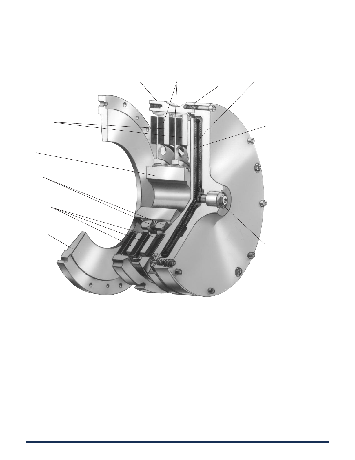
Floating Plate
Hub
Ductile Center
Plate
Grooved Friction
Disc
Demountable
Backplate
(Optional)
Pressure
Plate
Airtube Holding
Plate
Roto-coupling
High Torque
Air-Tube
Selection Requirements
To properly select a High Torque Clutch
and Low Inertia Brake, the following
information must be determined.
1. Torque necessary to do the work (clutch)
2. Rotating inertia to be stopped and started
3. Heat generated by each stop/start
4. Torque necessary to stop inertia (brake)
5. Shaft size
Wichita High Torque Clutches provide the
highest torque to size ratios of any Wichita
Clutch. They provide smooth controlled starts
and stops and are designed for minimum
power loss due to low rotating inertia.
• Extremely fast response
• No lubrication
• High torque to size ratio
• Low rotating inertia
High Torque Clutches
Ring
Very Low Inertia
Drive Plate Assembly
Bonded or Riveted
Shims
B
Air Tube Disc Clutches and Brakes
P-1100-WC 1/12
Wichita Clutch 800-964-3262 45
Data
Rated Tonnage. . . . . . . . . . . . . . . . . . . . As Re quired
Crankshaft Speed . . . . . . . . . . . . . . . . . 30 RPM
(Continuous Run)
Clutch-Brake Shaft RPM . . . . . . . . . . . . 204 RPM
Crankshaft Speed . . . . . . . . . . . . . . . . . 30 RPM
Degrees of Crank to start . . . . . . . . . . . 90°
Degrees of Crank to stop . . . . . . . . . . . 90°
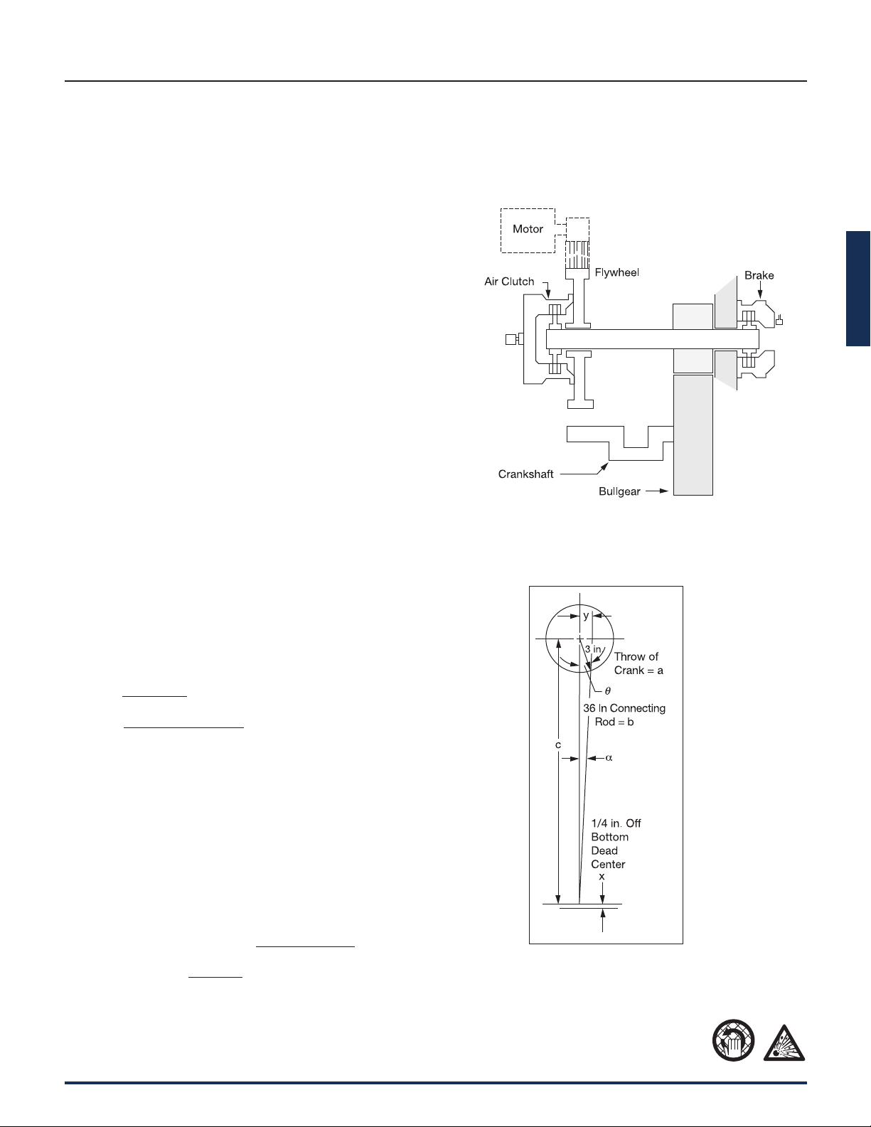
Connecting Rod Length = b . . . . . . . . . 36 in.
Stroke. . . . . . . . . . . . . . . . . . . . . . . . . . . 6 in.
1/2 of Press Stroke (throw) = a . . . . . . . 3 in.
WR
2
of Parts on Backshaft . . . . . . . . . . 78.2 lb.ft.
2
WR
2
of Parts on Crankshaft . . . . . . . . . . 39,091 lb.ft.
2
Material Shear Stress. . . . . . . . . . . . . . . 45,000 PSI
Blade Width . . . . . . . . . . . . . . . . . . . . . . 60 in.
Shaft Size . . . . . . . . . . . . . . . . . . . . . . . . 4 in.
Maximum Material to be Sheared . . . . . x
Air Pressure Available . . . . . . . . . . . . . . 100 PSI
Calculations
Torque @ Crank
=
(Material Shear Stress) (x) (Blade Width) (Torque Arm)
Torque arm = y = (x) (tan α )
c = a + b – x
= 3 + 36 – .25
= 38.75 in.
Cos α
=
b
2
+ c
2
– a
2
2 bc
=
(36)
2
+ (38.75)
2
– (3)
2
(2) (36) (38.75)
= .99948
α = 1.8478˚
Torque Arm = y = (c) (tan α )
= (38.75) (tan 1.8478˚)
= (38.75) (.03226)
= 1.25 in.
Torque @ Crank
=
(Material Shear Stress) (x) (Blade Width) (Torque Arm)
= (45,000) (.25) (60) (1.25)
= 843,750 lb.in.
Torque @ Clutch
=
(Torque @ Crank) ÷
Clutch RPM
Crankshaft RPM
= 843,750 ÷
204 RPM
30 RPM
= 124,081 lb.in.
Selection Example

Air Tube Disc Clutches and Brakes
46 Wichita Clutch 800-964-3262
P-1100-WC 1/12
Estimated time to start
=
Start Angle 60
360° Crankshaft RPM
=
90˚ 60 = 0.5 sec.
360˚ 30
P
1
= Line pressure to clutch
P
2
= Required pressure to clutch
LN = Natural log
k = Inflation coefficient
(ATD-224 H.T. @ 100 PSI)
= 2,600
u = For ATD-224 H.T. Clutch @ 100 PSI
= 2.5
Time to 26% of line pressure.
= 0.027 seconds
Clutch will be fully inflated at 90˚ of crank shaft
rotation.
Clutch exhaust time @ 100 PSI = E = .078
(page 52).
Note:
This application example is for preliminary
sizing only. Contact a Wichita Sales Engineer
or the factory for final selection.
High Torque Clutches
Clutch Selection
Per the application factors on page 23 a “Back
Geared Press is ‘Group C’.”
HP Torque 124,081
100 RPM
=
630
=
630
= 197
The preliminary clutch selection based on
124,081 lb.in. and 197 HP/100 RPM is an
ATD-224 Low Inertia High Torque Clutch.
(page 48)
A Low Inertia High Torque Clutch was chosen
because of the continuous duty (non-cyclic)
operation having a rel a tive ly low heat HP
requirement.
ATD-224 Low Inertia High Torque Clutch =
280 HP/100 RPM
Rated Torque = 480,000 lb.in @ 100 PSI
Required clutch air pressure is:
PSI =
Clutch required torque x (100 PSI)
Catalog rated torque @ 100 PSI
Actual required clutch PSI
PSI =
124,081
x (100 PSI)
480,000
= 26 PSI minimum is required.
This application has 100 PSI available.
Contact velocity of rotating disc is:
V
c
=
(Diameter of Center Plate) (π) (RPM)
12 in.ft.
=
24 ft.
12
(π) (204) = 1,282
min.
(Ductile iron is not required, see page 23).
Maximum bore for ATD-224 High Torque Low
Inertia Clutch = 7 in.
Check clutch inflation time for 90˚ start angle (see
page 52, PSI pressure curves)
t =
t =
LN
2,600
LN
k
P
1
P
1
- P
2
1
u
[ ]
[ ]
[ ]
100
100 - 26
1
2.5

B
Air Tube Disc Clutches and Brakes
P-1100-WC 1/12
Wichita Clutch 800-964-3262 47
[ ]
[ ]
Low Inertia Brake Selection
To properly size a brake, the total rotating inertia
reflected to the clutch and brake shaft must be
known.
Alternate shaft WR
2
referred to clutch shaft
=
Alternate Alternate shaft RPM
2
shaft WR
2
clutch shaft RPM
= 39,091 30
2
204
WR
2
referred to = 845.4 lb.ft
2
clutch-brake shaft @204 RPM
Total inertia = 78.2 lb.ft.
2
Back shaft WR
2
Clutch hub &
drive plate WR
2
from = 101.0 lb.ft.
2
Specification Table
Estimate brake WR
2
= 101.0 lb.ft.
2
(assume same as clutch)
Total WR
2
referred = 1,125.66 lb.ft.
2
to clutch-brake (Estimated)
Estimated time to stop:
=
Start Angle 60
360º
Crankshaft RPM
=
90º 60
= .5 sec.
360º
30
The deceleration torque is:
T= 12
WR
2
Brake RPM
32.2 9.5(t)
= 12
1125.6 204
32.2 9.5 (.5)
Deceleration Torque = 18,015 lb.in.
The HP / 100 RPM for this application is:
HP
=
Torque (lb.in.)
=
18,015
= 29 HP/100 RPM
100 RPM 630 630
Consult the Specification Table on pages 36-37
to select a brake based on torque and HP/
100 RPM. Under "Duty C", an ATD-214 brake
has 32 HP/100 capacity and 55,250 lb.in.
torque. The rotating inertia of an ATD-214
Low Inertia Brake is 11 lb.ft.
2
. Therefore, the
actual rotating inertia reflected to brake is
1035.6 lb.ft.
2
.
[ ]
The actual
= 12
1035.6 204
deceleration torque 32. 2 9.5
= 16,575 lb. in.
Required air pressure is:
Brake
=
Brake required torque x (100 PSI)
Catalog rated torque @ 100 PSI
=
16,575 lb. in.
x 100
55,250 lb. in.
= 30 PSI minimum
This application has 100 PSI available.
The average heat HP each stop
=
(Brake Torque)
x RPM x 1/2
63,000
=
16,575
x 204 x .5
63,000
= 26.8 HP
Friction area necessary to absorb heat =
heat HP
=
Heat HP
=
26.8
= 39 in.
2
Absorbtion rate for .5 sec.
.7 .7
(see page 174 )
An ATD-214 Low Inertia Brake has 316 in.
2
of
friction lining available to absorb heat
generated by stopping. Maximum bore for
an ATD-214 Low Inertia Brake is 4-1/8 inches.
Based on the given application data and
the following calculations, an ATD-224 Low
Inertia High Torque Clutch and ATD-214
Low Inertia Brake have been selected as
having sufficient torque and heat dissipation
capacity with minimum diameter and
sufficient bore capacity.
Note:
These application examples are for
preliminary sizing only. Contact a
Wichita Sales Engineer or the
factory for final selection.
[ ]
[ ] [ ]
[ ]
[ ] [ ]
[ ] [ ]
[ ]
High Torque Clutches

Air Tube Disc Clutches and Brakes
48 Wichita Clutch 800-964-3262
P-1100-WC 1/12
High Torque Clutches
Specifications
Model Slip Torque Capacity Duty Factors Max. Bore
Size Assembly lb.in. Nm HP/100 RPM Rect. Key
ATD- Number 80 PSI 100 PSI 5.5 BAR 7 BAR ABCDin. (mm)
HTC 104 6-004-100-400-0 800 1,000 90 113 1.6 1.2 0.6 0.3
1.00 (25)
HTC 204 6-004-200-802-0 1,600 2,000 180 226 3.2 2.4 1.2 0.6
HTC 106 6-006-100-400-0 4,000 5,000 475 602 8 5.7 2.8 1.4
2.00 (50)
HTC 206 6-006-200-400-0 8,000 10,000 950 1,204 16 11.4 5.7 2.8
HTC 108 6-008-100-407-0 8,800 11,000 977 1,243 17 13 63
HTC 208 6-008-200-417-0 17,600 22,000 1,953 2,486 34 25 13 6 2.38 (60)
HTC 308 6-008-300-400-0 26,400 33,000 2,930 3,729 51 38 19 9
HTC 111 6-011-100-408-0 20,000 25,000 2,220 2,825 38 28 14 7
HTC 211 6-011-200-422-0 40,000 50,000 4,440 5,650 76 56 28 14 2.63 (67)
HTC 311 6-011-300-406-0 60,000 75,000 6,660 8,475 114 84 42 21
HTC 114 6-014-100-405-0 38,400 48,000 4,261 5,423 75 55 27 14 4.13 (105)
HTC 214 6-014-200-403-0 76,800 96,000 8,522 10,846 160 114 55 28 3.63 (92)
HTC 314 6-014-300-411-0 115,200 144,000 12,783 16,269 225 165 81 42 4.63 (118)
HTC 116 6-016-100-403-0 59,480 74,350 6,600 8,400 118 91 47 24
HTC 216 6-016-200-402-0 118,960 148,700 13,200 16,800 236 182 94 47 4.00 (102)
HTC 316 6-016-300-401-0 178,440 223,050 19,800 25,200 354 272 142 71
HTC 118 6-018-100-400-0 84,000 105,000 9,321 11,863 165 120 60 30
HTC 218 6-018-200-400-0 168,000 210,000 18,642 23,726 330 240 120 60 4.75 (120)
HTC 318 6-018-300-400-0 252,000 315,000 27,963 35,589 495 360 180 90
HTC 121 6-021-100-400-0 136,000 170,000 15,091 19,207 270 208 108 54
HTC 221 6-021-200-401-0 272,000 340,000 30,182 38,414 540 415 216 108 6.00 (152)
HTC 321 6-021-300-400-0 408,000 510,000 45,273 57,621 810 623 324 162
HTC 124 6-024-100-401-0 192,000 240,000 21,305 27,116 385 280 140 70
HTC 224 6-024-200-405-0 384,000 480,000 42,610 54,232 770 560 280 140
6.00 (152)
HTC 324 6-024-300-401-0 576,000 720,000 63,915 81,348 1,155 840 420 210
HTC 424 6-024-400-400-0 768,000 960,000 85,220 108,464 1,540 1,120 560 280
HTC 127 6-027-100-404-0 289,680 362,100 32,144 40,911 575 442 230 115
6.50 (165)
HTC 227 6-027-200-411-0 579,360 724,200 64,288 81,821 1,150 884 460 230
HTC 327 6-027-300-402-0 869,040 1,086,300 96,432 122,732 1,724 1,326 690 345 6.00 (152)
HTC 130 6-030-100-400-0 376,000 470,000 41,722 53,101 750 535 270 135
7.25 (184)
HTC 230 6-030-200-408-0 752,000 940,000 83,445 106,203 1,500 1,070 540 270
HTC 330 6-030-300-415-0 1,128,000 1,410,000 125,167 159,304 2,250 1,605 810 405 8.00 (203)
HTC 136 6-036-100-400-0 752,000 940,000 84,445 106,200 1,555 1,120 560 280
8.00 (203)
HTC 236 6-036-200-409-0 1,504,000 1,880,000 166,890 212,400 3,100 2,240 1,120 560
HTC 336 6-036-300-404-0 2,256,000 2,820,000 250,335 318,600 4,665 3,360 1,680 840 9.25 (235)
HTC 148 6-048-100-400-0 1,888,000 2,360,000 209,500 266,637 3,745 2,690 1,345 670
HTC 248 6-048-200-406-0 3,776,000 4,720,000 419,000 533,273 7,490 5,380 2,690 1,345 18.00 (455)
HTC 348 6-048-300-403-0 5,664,000 7,080,000 628,500 799,910 11,235 8,070 4,035 2,010
Maximum Air Pressure is 100 PSI / 7 BAR.
 Loading...