

Page 1
Industrial Clutch Products
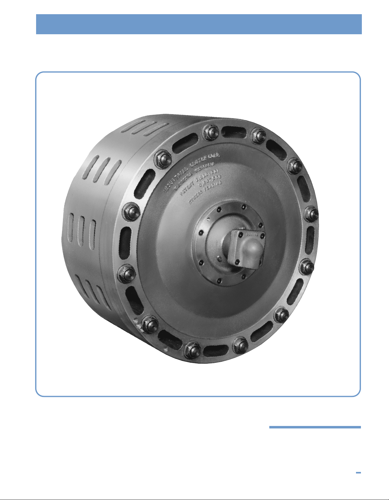
MODEL LKM
Air Set Marine Clutches
I N D U S T R I A L C L U T C H P R O D U C T S 40
Page 2

LKM Clutch Design Features
Rotary air inlet.
Compact multiple disc construction means less overhung weight and minimum gear center requirements.
Clutch designed with total attention given to maximizing ventilation for cool-running operation and the ability
to perform high energy engagements with minimum temperature build-up.
Precision machining of all components ensures positive interchangeability of all mating parts.
Outboard quill support bearing
cavity machined integral with the
clutch cylinder in a steel or cast
iron sleeve.
Positive Plate Separation
Separating springs are integral
with each clutch disc to positively
separate and hold the discs in a
fixed disengaged position.
Cylinder/piston made of high
strength aluminum alloy to
minimize overhung weight.
High strength hardened alloy
s
teel drive hub splines coated
with a baked-on high temperature
solid film lubricant for excellent
c
om-patibility and longevity.
Inner disc drive spline
length sized for maximum
load-carrying capacity.
High quality
non-asbestos
lining materials
and maximum
areas ensure
excellent heat
dissipation and
lining life.
High strength hardened alloy steel
drive studs ensure free plate motion
during engagement and disengagement. The use of drive studs, rather
than splines, allows wear particles
and other contaminants to exit the
clutch as well as provides an
excellent path for cooling air flows.
41 I N D U S T R I A L C L U T C H P R O D U C T S
Page 3

LKM Clutch Design Features
Model LKM-330-B clutches, each rated 5250 HP @ 500 RPM connect dual engine
inputs to a single propeller on a Falk Model 55 x 20 DMA1-S marine gear.
LKM AIR SET MARINE CLUTCH DEVELOPMENT HISTORY
The Model LKM marine clutch incorporates many of the
features found in our Model LK clutch series with some
notable exceptions. Cyclic applications, where the LK style
finds its most frequent use, contain duty cycles which bear
little resemblance to marine main propulsion service. Marine
clutches are required to make infrequent, yet in some
instances, severe engagements from a heat standpoint. The
clutches are also called upon to run for extended periods in
the engaged position (ahead clutches) and for extended
periods in the disengaged position (reverse clutches).
The Model LK clutches were rugged enough to handle the
load duty cycle from a torque and heat standpoint but
required modification to their separation systems in order to
be suitable for marine service. Industrial Clutch Products
was the first to recognize the importance of positive plate
separation for marine service and all clutches installed in
marine service contained this feature. Disc clutches for
marine service without positive plate separation have
experienced a sad approval rating from users.
This is particularly true in forward/reverse service where,
strangely enough, the unloaded reverse clutch gives the
greatest degree of trouble. Because of the gearing
arrangement, the outer members of this clutch rotate in
Photo courtesy of Falk Corporation
one direction while the inner member rotates in the other.
This gives rise to the term “twice relative rotation.” The cant
of the gear to which these clutches are mounted in order to
align with the propeller shaft as well as vessel motion due to
wave action causes the clutch plates, if not positively
separated, to kiss and wear or burn-out. Exactly the same
result would occur if one were going down the road in an
automobile at a high rate of speed with the brake pedal
lightly depressed.
To eliminate this, Industrial Clutch Products designed and
patented positive plate separation which has accrued over
30 years of field experience in marine main propulsion
service. The separating system is self-adjusting for wear and
no adjustments are ever required by the user during regular
use or during routine maintenance. No plate contact can
occur with this unique positive plate separation system and
the many advantages of the disc clutch can be fully realized
for marine service.
The incorporation of positive plate separation, a bearing
cavity for the outboard quill bearing, and modifications made
to increase the load carrying capacity on a continual basis
changed the time-proven LK design into the Model LKM
marine clutch.
I N D U S T R I A L C L U T C H P R O D U C T S 42
Page 4

Model LKM
D
E
C
G
N
A
L
B
M
F
K
J
I
H
3/4"-NPT
ROTARY
AIR INLET
MOUNTING
PLATE ADAPTORS
AVAILABLE AS
AN OPTION
D
OUBLE DISK LKM CLUTCH
DIMENSIONAL DATA All dimensions in inches
LKM GH N
Model ABCDEFMin.-Max. No.-Size IJKLMMin.-Max.
LKM-213 8.69 7.86 16.63 16.25 14.65 5.25 2-7/8 - 3-1/2 8-15/16 1 .44 1.50 .18 4 3-1/2 - 4-3/8
LKM-313 10.50 9.69 16.63 16.25 14.63 7.06 2-7/8 - 3-1/2 8-15/16 1 .44 1.50 .18 4 3-1/2 - 4-3/8
LKM-218 11.31 10.31 22.63 21.50 20.00 7.75 2-7/8 - 4-1/8 12 - 1-1/16 1 .56 1.38 .18 4 4-1/2 - 5-9/16
LKM-318 14.19 13.19 22.63 21.50 20.00 10.63 2-7/8 - 4-1/8 12 - 1-1/16 1 .56 1.38 .18 4 4-1/2 - 5-9/16
LKM-221 11.06 10.44 25.00 24.50 22.50 6.81 3-3/8 - 5-1/2 12 - 1-1/16 1 .31 2.19 .18 4 4-1/2 - 5-15/16
LKM-321 13.63 13.00 25.00 24.50 22.50 9.38 3-3/8 - 5-1/2 12 - 1-1/16 1 .31 2.19 .18 4 4-1/2 - 5-15/16
LKM-225 14.38 13.63 29.75 29.25 27.00 8.50 4-5/8 - 7-1/2 12 - 1-5/16 1-1/4 .78 3.31 .18 4 4-1/2 - 6
LKM-325 17.63 16.86 29.75 29.25 27.00 11.75 4-5/8 - 7-1/2 12 - 1-5/16 1-1/4 .78 3.31 .18 4 4-1/2 - 6
LKM-230 15.63 13.25 35.50 35.00 32.00 9.00 5-1/4 - 9-5/8 12 - 1-1/4 2 1.06 3.06 .25 4-5/8 5 - 8
LKM-330 18.94 16.56 35.50 35.00 32.00 12.25 5-1/4 - 9-5/8 12 - 1-1/4 2 1.06 3.06 .25 4-5/8 5 - 8
LKM-235 15.63 13.38 41.50 40.75 36.88 7.69 8 - 12 24 - 1-1/4 2 1.13 3.88 .25 3-7/8 6 - 9-1/16
LKM-335 18.06 15.81 41.50 40.75 36.88 10.13 8 - 12 24 - 1-1/4 2 1.13 3.88 .25 3-7/8 6 - 9-1/16
LKM-242 18.27 16.58 48.75 48.00 44.00 10.75 8 - 12 24 - 1-3/4 3 1.00 4.00 .25 3-7/8 6-1/2 - 9-1/16
LKM-342 22.13 20.44 48.75 48.00 44.00 14.63 8 - 12 24 - 1-3/4 3 1.00 4.00 .25 3-7/8 6-1/2 - 9-1/16
LKM-248 21.02 18.77 54.75 54.00 50.00 11.56 9-1/8 - 14 24 - 1-3/4 3 1.38 5.00 .25 2-3/4 10 - 14.50
LKM-348 25.50 23.25 54.75 54.00 50.00 16.00 9-1/8 - 14 24 - 1-3/4 3 1.38 5.00 .25 2-3/4 10 - 14.50
NOTES: 1.) Use certified drawing dimensions only for final layouts.
2.) DXF and IGES files available upon request.
3.) Dimensions subject to change without notice.
4.) Consult factory or refer to application information when selecting units.
43 I N D U S T R I A L C L U T C H P R O D U C T S
Page 5

OPERATIONAL DATA
tatic Dynamic
S
orque @ Torque @ Weight Weight Total WR
LKM 125 PSIG 125 PSIG Outer Inner Weight Outer Inner Speed
Model (lb.-in.) (lb.-in.) (lbs.) (lbs.) (lbs.) (lb.-ft.2) (lb.-ft.2) (RPM)
LKM-213 94,600 82,000 155 65 220 50 7 2100
LKM-313 142,000 123,000 220 90 310 70 9 2100
LKM-218 200,000 173,333 440 135 575 255 24 1600
KM-318 300,000 260,000 480 200 680 284 35 1600
L
LKM-221 382,000 331,000 430 200 630 320 50 1400
KM-321 572,000 445,733 525 285 810 396 71 1400
L
KM-225 510,000 442,000 730 360 1,090 775 110 1200
L
KM-325 765,000 663,000 850 451 1,301 836 158 1200
L
KM-230 1,000,000 866,666 1,095 475 1,570 1,456 222 1000
L
KM-330 1,500,000 1,300,000 1,290 710 2,000 1,894 320 1000
L
KM-235 1,455,000 1,261,000 1,925 675 2,600 3,091 472 850
L
KM-335 2,183,000 1,892,000 2,088 1,012 3,100 4,580 720 850
L
KM-242 2,716,000 2,354,000 2,770 1,098 3,868 7,495 990 700
L
KM-342 4,074,600 3,531,320 3,305 1,565 4,870 9,148 1,458 700
L
KM-248 2,466,600 3,004,386 3,942 1,535 5,477 13,048 1,752 650
L
KM-348 5,200,000 4,506,666 4,721 2,205 6,926 15,989 2,584 650
L
T
2
2
R
W
SELECTION CHART – Marine Engine Horsepower (S.F. 2.0 @ 125 PSIG)
Model LKM
aximum
M
Clutch
RPM
250 500 750 1000 1250 1500 1750 2000 2500 3000 3500 4000 4500 5000 6000 7000 8000 9000 10000
50 318
1
200 218 221
250
300
350
400 213 218
450 213
500 213
550 213
600 213
650 213
700 213 213
750 213 213
800 213 213
850 213 213
900 213 213
1000 213 213 213
1100 213 213 213
1200 213 213 213
1400 213 213 213 213
1600 213 213 213 213
1800 213 213 213 213 213 313 313 313
2000 213 213 213 213 213 213 313 313 –––––––––––
321 325
225 230 235 235 242 242 248 248
321 325
225 230 225 225 242 242 248 248
313 318
218 221 230 230 225 225 242 242 242 248
313 318
218 221 225 230 230 235 235 242 242 242 248 248
313
218 221 225 230 230 235 235 235 242 242 242 248 248
221 321
221
318
218
318
221 225 225 230 235 235 235 242 242 248 248 248
313 318 318
218 221 221 225 225 230 235 235 235 242 242 248
313
218
218 221 225 230 230 235 235 235 242 242 242
313
218
218 221 221 225 225 230 235 235 235 242 242 242
313
218
218 221 221 225 225 230 230 235 235 242 242 242
313
218 218
218 221 221 225 225 230 230 235 235 242 242 242
313
218 221 221 225 230 230 235 235 235 242 242
313
218 221 221 221 225 225 230 230 230 235 235
313
218 221 221 225 225 230 230 235 235 235
313
218 221 221 221 225 230 230 230 235 235 235
313 313
218 218 221 221 221 225 225 230 230
330 330
30
2
230 230
325 325
321
221
221
318
318 318
318 318
218
218
218 218
218 218
313
218 221 221 225 225 230 230
313
218 221 221 225 225
313 313
218 218 221 221 221 225 225
325 325
321
321
321
321 321
321 321
221
221 221
221
221 221
318 318
318 318
318 318 318
318 318
318 318 318
318 318 318
218
218 218
218 218 218
218 218
313 313
218 218 221 221
313 313 313
218 218 218
335 335
30
3
330 330 335 335
330 330 335 335 335
230
330 330
230
325 325
321
321
321 321
221
221 221
318 318
218 218
230
325
230 230
325
321
325 325
225
321
321 321 325 325
321 321 325 325
321
321 321 325 325 325
221
321 321
221
221
221
221 221
318 318
318 318 318
318 318
218 218 318 318 ––––––––
–––––––––––
342 342
42
2
242 242
330
330 330 330 335 335 335
330 330 330 335 335
230 230
230
325
230 230
325 325
321
321
321
321
321 321
321 321
321 321
221
221
221 221 321 321 321 ––––
42 348 348 ––––
3
342 342
242 242
335 335 335
330 330 330 335 335
330 330 330 335 335 335
330 330 330 335 335 335
230 230
230 230 230
230 230
325 325
325 325 325
325 325
321
321
321 321 325 ––––
321 321
348 348 348 ––
342
242
330 330
330 330 335 335 335
330 330 330 335 335
230 230
230 230
230
230 230 330 330 330
325 325
321 325 325 –––
342 342 348 348
342 342
242
242
330
330 330
330 330 330
330 330 330
230 –––
342 348
342 342
342 342 342
242 242
335 335 335
342
342
242 242
242
335 335
335
330
120001400016000 1800020000
–––– 150
–
––––– 200
––––– 250
348 –––– 300
342 348 ––– 350
342 348 348 –– 400
342
342 348 348 – 450
248
342
248 248
342 342
248 248
242
242
335
242
335 –––– 750
335 –––– 800
––––– 850
––––– 900
–––––1000
–––––1100
–––––1200
–––––1400
–––––1600
–––––1800
–––––2000
342
342
342 342
248 248
342 342
248 248
242 242 342 342 700
342 348 500
342 348 348 550
342 348 600
342 342 650
Clutch
RPM
I N D U S T R I A L C L U T C H P R O D U C T S 44
Page 6

Model LKM
Tact = Actual Static Capacity = Cat. Stat. Rating x
Supply Press
Rated Press
Tact = 510000 x = 612000 LBIN
150
125
Actual Serv. Fact. = = = 2.91
Tact
Working Torq
612000
210083
Operating Pressure =
125 x Reqd. Serv. Fact. x Work Torq
Cat. Stat. Torq. Rating
Operating Pressure = = 103 PSIG
125 x 2.0 x 210083
510000
Working Torque = = = 210083 LBIN
HP x 63025
RPM
Minimum Static Torque = Work Torque x Service Factor
= 210083 x 2.5 = 525208 LBIN
3000 x 63025
900
Minimum Catalogue Rating = Static Torque Reqd x
Rated Press
Supply Press
Minimum Catalogue Rating = 525208 x = 437674 LBIN
125
150
LKM Marine Clutch Application Information
The selection chart on the previous page is suitable for
forward/reverse main propulsion service at 125 PSI
actuation.
For controllable pitch propellers, dredge pumps, winches,
and fire pumps use the following service factors.
Service
Machinery Factor
Main Propulsion 1.8
Cont. Pitch Prop.
Winches, Centrifugal 1.65
Fire Pumps
Centrifugal Dredge Pumps 2.5
Main Propulsion Continuous Consult
Slip from Engine Idle Factory
Example: Centrifugal dredge pump Disconnect clutch
application.
The allowable speed for the Model LKM-225-B is 1200 RPM
nd exceeds the operating speed of 900 RPM. The selection
a
is appropriate from a torque and speed standpoint.
Dredge pumps can draw extraneous matter into the pump
which may suddenly stall the pump impeller. This places a
huge shock on the drive system and the clutch is called
upon to act as a fuse in these instances. A review of the
magnitude of the actual applied service factor is always
required to be certain the drive system components can
withstand these overloads. It may be necessary to reduce
the clutch service factor which increases the likelihood of
clutch damage but saves a more costly drive system repair.
The preferred way to reduce the service factor is to adjust
the operating air pressure accordingly and maintain the
clutch size as originally selected.
The following procedure may be used to calculate the air
pressure required for any desired service factor. In this
example, the recommended service factor was 2.5. We
selected a Model LKM-225-B clutch since it was the closest
unit that met or exceeded the calculated torque requirement
of 437,674 LB-IN. Note that the actual service factor is 2.91.
IInnppuutt PPaarraammeetteerrs
The engine is rated 3000 HP and the shaft the clutch is to
be mounted on is rotating at 900 RPM. The available air
pressure is 150 PSIG.
The Model LKM-225-B (rated at 510,000 LB-IN) is selected
from the static torque column shown in the operational data
chart on the previous page. This unit is the nearest size that
meets or exceeds the value of 437,674 LB-IN required.
s
If, by way of example, it was decided that a service factor
of 2.0 was required, the supply air pressure should be set at
103 PSI.
To summarize, a Model LKM-225-B operating at 103 PSIG
will provide a 2.0 service factor for this application.
45 I N D U S T R I A L C L U T C H P R O D U C T S
 Loading...