

Page 1
Air Tube Disc Clutches and Brakes
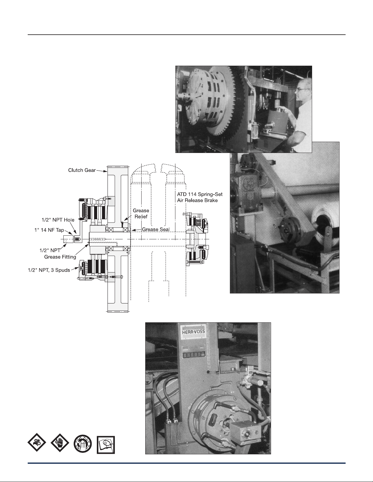
Typical Applications
Wichita High Torque Clutch
provides fast acceleration and
long life on metalforming
punch presses.
Typical Wichita clutch
and brake mounting
on a press
22 Wichita Clutch 800-964-3262
Wichita Low Inertia Brakes increase tension control for
paper unwind stands.
Wichita Spring-Set
Air Release Brakes
insure accuracy and
high performance for
a metal shear.
P-1100-WC 1/12
Page 2

Clutch sizes are affected by the
following variables:
Air Tube Disc Clutches and Brakes
Application Factors
1. Machines that operate under smooth
loads require smaller clutches. These
machines are driven by either
multi-cylinder high speed engines or
electric motors with reduced starting
current.
2. Drives that require high starting
current motors will require clutches
with sufficient torque to prevent
excessive slipping while starting.
3. Starting torque may be high, which
requires a fast clutch response time
to transmit the required torque; or,
extended clutch slip time is required
to protect the prime mover.
This chart gives application factors
ranging from light duty (the A group) to
extra heavy duty (the D group).
After initial usage is determined, see
4. Starting torques may be very low
compared to the normal torque,
which may result in the clutch not
being fully pressurized prior to the
time of full torque requirement. This
will cause the clutch to overheat from
slippage. Clutch inflation time in this
instance is very important.
5. Clutches on most machines are
designed to slip prior to damage
from shockloads. As a result, the
clutch may require periodic
main te nance; therefore, the clutch
should be located for easy access in
the power train.
Clutch es should also be located for
max i mum cooling air. In instances
“Selection Requirements” to com plete
the selection process. The in fla tion and
exhaust time should also be checked to
insure proper response.
where this is not pos si ble, forced air
cooling may be nec es sary for
extended clutch life.
6. Safe clutch operating speeds should
be maintained in product design.
Maximum Clutch Contact Velocity
FPM Material
(Recommended
6,000
9,000
upper limit for slip)
ductile iron
cast iron
12,000 steel
Dynamic balancing recommended when
peripheral speeds exceed 3500 FPM.
The maximum speeds shown are safe
op er at ing speeds based on years of
Wichita testing. Please do not exceed
these limits.
Application Guidelines
B
Field of Application Group A Group B Group C Group D
Pumps Centrifugal Reciprocating compressors Reciprocating compressors
compressors over 2 cylinders, one or two cylinders
centrifugal fans & blowers
Agitators Liquid Semi-solid Solids
Brick Brick press, extruder, pug mill
manufacturing
Canning & bottling machine Bottle-can feeders, filling, mixers
Engine driven equipment Crane, hoist, engine Crowd
Grinding mills Ball-rod-sag-pebble Crushers, shakers
Lumber processing Yarder Carriages, conveyers Chipper, logger
Marine Propulsion clutch CP wheel Shaft brakes, propulsion
reversing type, anchor winch
Bulk material Conveyors evenly loaded, Feeders Elevators
handling line shaft evenly loaded
Metal production & Coilers, slitters, press brake, Draw bench, rolling mill, Hammer mill, forming
metalforming non-geared press, geared press shear, back geared press, press, forging press,
deep draw press, transfer header press, knuckle press
press, toggle press
Paper industry dryer Fourdrinier to 500 FPM, Fourdrinier to 1800 RPM
sections & calenders paper mill plane & press selections, calenders
Consult factory smoothing press & dryers
Petroleum Drilling & service rig master Mud pumps,
production clutches, compound clutches, PTO clutches
rotary, drum
Rubber Transfer machines Banberry mixer, drum mixer, Centrifuge
manufacturing evenly loaded extruder, calender
P-1100-WC 1/12
Wichita Clutch 800-964-3262 23
Page 3
Air Tube Disc Clutches and Brakes
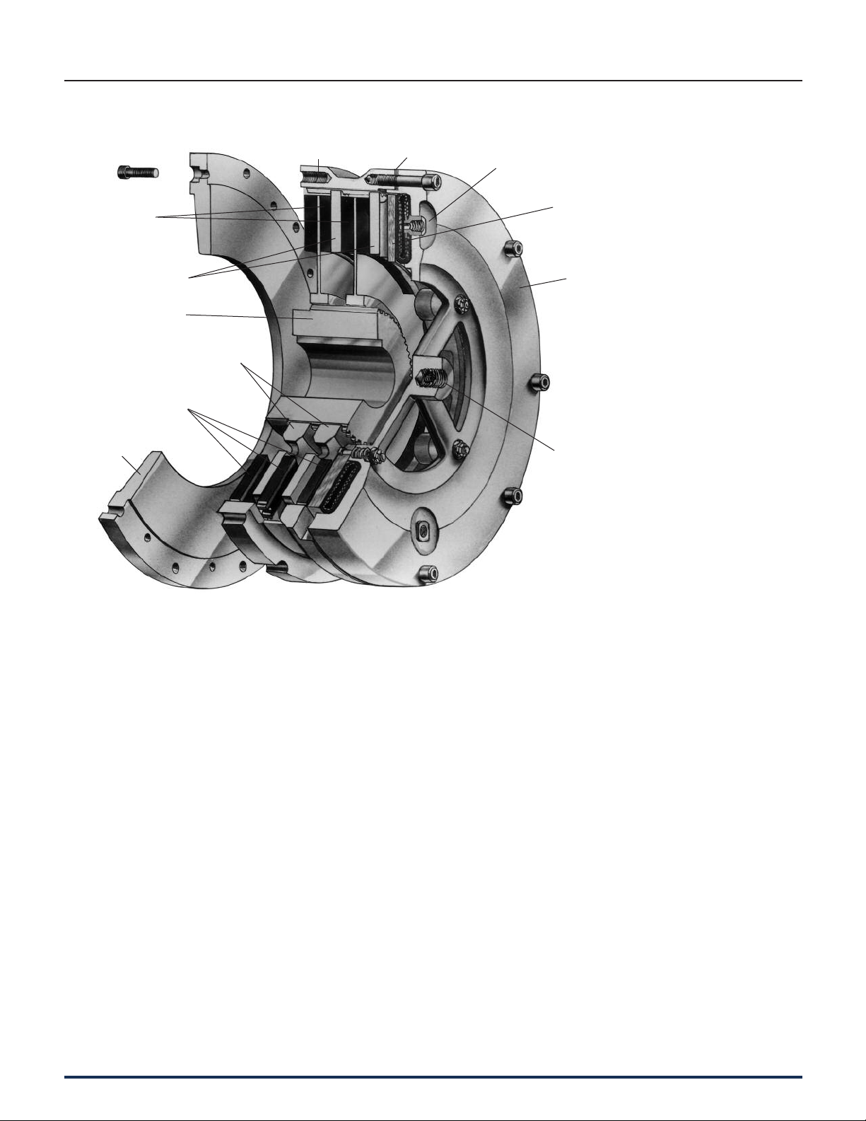
Low Inertia and Very Low Inertia Clutches and Brakes
Very Low Inertia
Drive Plate Assembly
with Bonded or
Riveted Pads
Floating Plate
Grooved
Friction Disc
Demountable
Backplate
(Optional)
Hub
Ductile
Center Plate
Ring Shims
Multiple Spud
Airtube
Pressure
Plate
Airtube
Holding
Plate
Roto-Coupling
Spider
Operating Features
The Wichita Air-Tube Disc Clutch com bines
all the best features of the disc type clutch with
all the advantages of direct air engagement.
The simplest and most trouble-free method of
applying air pressure is through direct axial
pressure ap pli ca tion by com pressed air in a
special com po si tion full-circle tube.
Wichita Clutches engage smoothly without
noise, shock or impact and release com plete ly
in a fraction of a second. Extremely fast action
is possible because of the small volume of air
re quired.
Clutches may be slipped moderately to control
the acceleration rate.
When large inertia loads are powered from
electric motors, smooth, controlled slip starts
by Wichita Clutches can keep power demands
below the allowed max i mum.
Heat generated by controlled slipping or
high cycle rate operation is dissipated by
the cen trif u gal blower design of these units.
Wichita Low Inertia and Very Low Inertia
Clutches and Brakes are de signed to be
com plete ly free from effects of cen trif u gal
force and self energization.
Torque developed is in direct proportion to air
pressure ap plied.
These clutches and brakes interface well with
automated controls through simple air and/or
electric circuits.
Water cooled, copper disc clutches are
available for use when power trans mis sion
needs require excessive or con stant slipping
which demands higher heat
dis si pa tion.
Wichita Clutches operate perfectly when
teamed with Wichita Brakes in pro duc tion
situations requiring tension control, cyclic
duty, or positioning.
Wichita Brakes have the same outstanding
performance characteristics as Wichita
Clutch es.
24 Wichita Clutch 800-964-3262
P-1100-WC 1/12
Page 4

Air Tube Disc Clutches and Brakes
Low Inertia and Very Low Inertia Clutches and Brakes
Selection Requirements
The selection of a Low Inertia Brake is
based on:
1. Torque required to stop a load.
2. Friction area necessary to absorb
rotational energy.
3. Contact velocity of rotating discs.
4. Maximum bore capacity of unit.
Selection example
To properly select a Low Inertia Brake for
a controlled deceleration application, the
following information is needed:
Speed . . . . . . . . . . . . . . . . . . 750 RPM
Shaft Dia.. . . . . . . . . . . . . . . . 5 in.
Inertia to Stop . . . . . . . . . . . . 2,473 lb.ft.
Stop Time . . . . . . . . . . . . . . . 5 sec.
Air Pressure Available . . . . . . 80 PSI
Calculations
Avg. HP =
3.2 x 10⁶x Stop Time
WR
2
X (RPM)
= 2,473 X (750)
3.2 x 106x 5 sec.
Swept Avg. HP
Friction =
HP ab sorp tion rate for 5 seconds
Area (see page 174)
=87 HP
= 202 in.
0.43
2
2
= 87 HP
2
Summary
As calculated, the torque required to stop the
load in 5 seconds is 14,547 lb.in. Wichita Low
Inertia Brakes are rated at 100 PSI.
This application has only 80 PSI available.
To determine the torque rating of a Low Inertia
brake at 80 PSI apply the following formula:
Application: Torque for a Low Inertia Brake
= Torque X Catalog Rated Pressure
Available Air Pressure
= 14,547 X = 18,183 lb.in.
100
80
Consult pages 26 and 36 for clutch and brake
spec i fi ca tions. A Low Inertia model 114 Brake
2
pro duc es 27,625 lb.in. torque at 100 PSI.
However, the bore capacity is 4.125 inches.
This application requires a 5 inch bore.
There fore, a Low Inertia 118 is to be
in ves ti gat ed.
Catalog Torque Rating = 64,500 lb.in.
@ 100 PSI
Maximum Bore Capacity = 5.25 in.
Catalog Swept Friction Area = 264 in.
2
Calculations show this application needs at
least 202 in.
2
to absorb the heat.
All of these ratings are acceptable for the given
application data.
Next, check contact velocity of rotating discs.
= Diameter of centerplate X RPM
3.82
B
P-1100-WC 1/12
Torque
25.5 x Stop Time
25.5 x 5
WR2x RPM
=
=
2.473 x 750
= 14,547 lb.in.
Using the above calculations, consult the
Low Inertia Specifications Chart on
pages 26 and 27.
=18" X 750
3.82
= 3,534 FPM
Standard material is sufficient up to 6,000 FPM
(see page 23). Balancing is recommended
above 3,500 FPM.
Therefore, a Low Inertia ATD-118 brake is
the optimum choice for this application.
A Spring-Set Air Release Brake is also
available (see page 58).
Note:
This application example is for pre lim i nary
sizing only. Contact a Wichita Sales Engineer
or the factory for final selection.
Wichita Clutch 800-964-3262 25
Page 5

Air Tube Disc Clutches and Brakes
Low Inertia Clutches
Specifications
Model Slip Torque Capacity Duty Factors Max. Bore
Size Assembly Drawing lb.in. Nm HP/100 RPM Rect. Key
ATD- Number Number 80 PSI 100 PSI 5.5 BAR 7 BAR ABCDin. (mm)
LIC 106 6-006-100-211-0 -100-900-9 3,160 3,950 340 435 6.2 4.4 2.2 1.1
LIC 206 6-006-200-200-0 -200-900-9 6,320 7,900 680 870 12.5 8.8 4.4 2.2
LIC 108 6-008-100-103-0 D-1718 5,600 7,000 620 790 11.1 842
LIC 208 6-008-200-101-0 -200-900-9 11,200 14,000 1,240 1,580 22.2 16 842.25 (57)
LIC 308 6-008-300-103-0 D-2843 16,800 21,000 1,865 2,375 33.3 24 12 6
LIC 111 6-011-100-102-0 -100-900-9 12,720 15,900 1,400 1,785 25 18 95
LIC 211 6-011-200-102-0 -200-900-9 25,440 31,800 2,800 3,570 50 36 18 10 2.50 (64)
LIC 311 6-011-300-100-0 B-322 38,160 47,700 4,235 5,390 75 54 27 15
LIC 114 6-014-100-102-0 -100-900-9 22,100 27,625 2,435 3,100 44 31 16 8
LIC 214 6-014-200-104-0 -200-900-9 44,200 55,250 4,870 6,200 88 62 32 16 3.50 (89)
LIC 314 6-014-300-100-0 B-329 66,300 82,875 7,355 9,365 132 93 48 24
LIC 116 6-016-100-100-0 D-327 30,270 37,838 3,360 4,275 60 46 24 12
LIC 216 6-016-200-100-0 -200-900-9 60,541 75,676 6,720 8,550 120 92 48 24 4.00 (102)
LIC 316 6-016-300-100-0 D-1205 90,811 113,514 10,080 12,825 180 139 72 36
LIC 118 6-018-100-100-0 -100-100-0 51,600 64,500 5,705 7,260 102 75 35 21
LIC 218 6-018-200-100-0 -200-900-9 103,200 129,000 11,410 14,520 204 150 70 42 4.75 (121)
LIC 318 6-018-300-101-0 D-680 154,840 193,550 17,115 21,780 306 225 105 63
LIC 121 6-021-100-100-0 D-127 69,887 87,359 7,755 9,870 139 107 55 28
LIC 221 6-021-200-100-0 -200-900-9 139,775 174,719 15,510 19,740 277 213 111 55 6.00 (152)
LIC 321 6-021-300-100-0 D-783 209,662 262,078 23,265 29,610 416 320 166 83
LIC 124H 6-025-100-100-0 D-347 122,960 153,700 13,575 17,275 243 180 90 40
LIC 224H 6-025-200-100-0 -200-900-9 245,920 307,400 27,150 34,550 487 360 180 80 6.00 (152)
LIC 324H 6-025-300-201-0 -300-900-9 368,880 461,100 40,725 51,825 729 540 270 120
LIC 127 6-027-100-100-0 -100-900-9 137,509 171,886 15,260 19,420 273 210 109 55
LIC 227 6-027-200-100-0 -200-900-9 275,018 343,773 30,520 38,840 546 420 218 109 6.50 (165)
LIC 327 6-027-300-100-0 D-689 412,527 515,659 45,780 58,260 819 630 327 164
LIC 130H 6-031-100-100-0 B-195 261,600 327,000 29,630 37,710 519 380 190 100
LIC 230H 6-031-200-349-0 -200-900-9 523,200 654,000 59,260 75,420 1,038 760 380 200 7.25 (184)
LIC 330H 6-031-300-104-0 -300-902-9 784,800 981,000 88,890 113,130 1,557 1,140 570 300
LIC 136 6-036-100-100-0 -100-900-9 406,400 508,000 44,920 57,175 805 600 295 165
LIC 236 6-036-200-100-0 D-570 812,800 1,016,000 89,840 114,350 1,610 1,200 590 330 9.00 (229)
LIC 336 6-036-300-100-0 -300-900-9 1,219,200 1,524,000 134,760 171,525 2,415 1,800 885 495
LIC 142 6-042-100-303-0 -100-900-9 580,800 726,000 69,160 81,660 1,150 850 425 235
LIC 242 6-042-200-309-0 -200-900-9 1,162,240 1,452,800 128,320 163,320 2,300 1,700 850 470 14.00 (355)
LIC 342 6-042-300-302-0 -300-303-9 1,742,400 2,178,000 192,480 244,980 3,450 2,550 1,275 705
LIC 148 6-048-100-300-0 -100-901-9 1,122,000 1,402,500 118,800 151,200 2,225 1,600 800 455
LIC 248 6-048-200-300-0 -200-906-9 2,244,000 2,805,000 237,600 302,400 4,450 3,200 1,600 915 18.00 (455)
LIC 348 6-048-300-110-0 -300-900-9 3,366,000 4,207,500 356,400 453,600 6,675 4,800 2,400 1,365
LIC 260 6-060-200-302-0 -200-907-9 4,760,000 5,950,000 473,000 602,000 9,440 5,950 3,470 1,940
LIC 360 6-060-300-201-0 -300-901-9 7,140,000 8,925,000 709,000 902,300 14,160 8,925 5,205 2,910 19.00 (480)
LIC 460 6-060-400-300-0 E-236 14,280,000 17,850,000 946,000 1,204,000 18,880 11,900 6,940 3,880
Maximum Air Pressure is 130 PSI / 9 BAR.
2.00 (50)
26 Wichita Clutch 800-964-3262
P-1100-WC 1/12
Page 6

Air Tube Disc Clutches and Brakes
Low Inertia Clutches
Specifications
Recom- Airtube Type Airtube
Model mended Balance Reg- High Swept Volume Total Clutch Hub & Center Plate
Size Clearance Speed Speed Speed Area in.3/(cm3) Wt. WR2/ J=mr
ATD- in. RPM RPM RPM* in.2New Worn lb. (kg) lb.ft.
LIC 106 1/16-3/32
LIC 206 3/32-5/32 78
LIC 108 1/16-1/8 56
LIC 208 3/32-5/32 1,675 1,750 3,000* 112 70 (32) 8.5 (0.357) 19 (8.6) 1.00 (0.042)
LIC 308 1/8-3/16 168
LIC 111 1/16-1/8 114
LIC 211 3/32-5/32 1,200 1,400 2,800* 228 170 (77) 34 (1.43) 45 (20.4) 4.50 (0.190)
LIC 311 1/8-3/16 342
LIC 114 1/16-1/8 158
LIC 214 3/32-5/32 950 1,200 2,200* 316 233 (106) 70 (2.95) 77 (34.9) 11.0 (0.464)
LIC 314 1/8-3/16 474
LIC 116 1/16-1/8 228
LIC 216 3/32-5/32 835 1,200 2,000* 455 326 (148) 125 (5.27) 106 (48.1) 19.6 (0.826)
LIC 316 1/8-3/16 683
LIC 118 1/16-1/8 264
LIC 218 3/32-5/32 750 1,000 2,000* 528 377 (171) 183 (7.72) 120 (54.4) 28.8 (1.214)
LIC 318 1/8-3/16 792
LIC 121 3/32-5/32 362
LIC 221 1/8-3/16 650 900 1,650* 724 582 (264) 356 (15.01) 198 (89.8) 61 (2.57)
LIC 321 5/32-7/32 1,086
LIC 124H 3/32-5/32 574
LIC 224H 1/8-3/16 550 700 1,400* 1,148 830 (376) 618 (26.05) 260 (117.9) 109 (4.6)
LIC 324H 5/32-7/32 1,722
LIC 127 3/32-5/32 730
LIC 227 1/8-3/16 500 700 1,400* 1,460 950 (431) 862 (36.3) 322 (146.1) 193 (8.1)
LIC 327 5/32-7/32 2,190
LIC 130H 3/32-5/32 827
LIC 230H 1/8-3/16 450 600 1,100* 1,654 1,411 (640) 1,552 (65.4) 546 (247.7) 370 (15.6)
LIC 330H 5/32-7/32 2,481
LIC 136 3/32-5/32 1,150
LIC 236 1/8 -3/16 375 600 900* 2,300 1,992 (904) 3,247 (136.9) 708 (321.1) 725 (30.6)
LIC 336 5/32-7/32 3,450
LIC 142 5/32-7/32 1,400
LIC 242 3/16-1/4 325 500 800* 2,800 2,732 (1,239) 5,750 (242) 1,197 (543) 1,385 (58)
LIC 342 7/32-9/32 4,200
LIC 148 1/8-1/4 2,010
LIC 248 5/32-7/32 275 400 700* 4,020 4,700 (2,132) 13,775 (581) 1,942 (881) 3,335 (141)
LIC 348 3/16-5/16 6,030
LIC 260 3/16-5/16 7,230
LIC 360 1/4-3/8 225 320 550* 10,845 11643 (5,281) 57,286 (2,415) 3,870 (1,755) 10,615 (448)
LIC 460 5/16-7/16 14,460
* Consult Factory for Special Assembly Number.
2,225 1,800 2,600*
39
1.8 11.9
(30) (195)
3.4 18.3
(56) (300)
5.5 30.5
(90) (500)
7.6 42.7
(125) (700)
9.8 56.1
(161) (919)
15.3 85.4
(251) (1,400)
18.3 97.6
(300) (1,599)
29.9 159
(490) (2,606)
29.9 159
(490) (2,606)
58.6 311
(960) (5,096)
110 415
(1,803) (6,801)
128 488
(2,098) (7,997)
217 824
(3,550) (13,500)
513 1,788
(8,407) (29,300)
27.5 (12) 2.5 (0.105) 6.40 (2.9) 0.24 (0.010)
40.5 (18) 3.3 (0.139) 12.17 (5.5) 0.46 (0.019)
62 (28) 7.5 (0.315) 11 (5.0) 0.54 (0.023)
92 (42) 99 (4.174) 28 (12.7) 2.00 (0.084)
133 (60) 27 (1.14) 23 (10.4) 2.30 (0.097)
208 (94) 52 (2.19) 121 (54.9) 7.00 (0.295)
184 (83) 56 (2.36) 46 (20.9) 5.7 (0.240)
292 (132) 80 (3.37) 121 (54.9) 16.7 (0.704)
257 (117) 103 (4.34) 59 (26.8) 10.2 (0.430)
358 (162) 125 (5.27) 151 (68.5) 29.6 (1.248)
311 (141) 158 (6.66) 73 (33.1) 15.0 (0.632)
472 (214) 219 (9.23) 180 (81.6) 43.2 (1.821)
467 (212) 303 (12.77) 116 (52.6) 32 (1.35)
730 (331) 450 (18.97) 272 (123.4) 92 (3.88)
637 (289) 468 (19.73) 132 (60.0) 56 (2.4)
1,025 (465) 735 (31.00) 379 (172.0) 160 (6.8)
770 (349) 706 (29.8) 187 (84.8) 98 (4.1)
1,112 (504) 969 (40.9) 555 (251.7) 285 (12.0)
1,035 (469) 1,170 (49.3) 298 (135.2) 189 (8.0)
1,751 (794) 1,788 (75.4) 810 (367.4) 477 (20.1)
1,455 (660) 2,368 (99.8) 461 (209.1) 372 (15.7)
2,610 (1,184) 4,057 (171.0) 1,134 (514.4) 1,091 (46.0)
1,967 (892) 4,721 (199) 680 (308) 705 (30)
3,704 (1,680) 9,191 (387) 1,324 (601) 1,809 (76)
3,158 (1,432) 9,325 (393) 1,101 (499) 1,785 (75)
6,540 (2,966) 18,000 (759) 2,950 (1,338) 4,925 (208)
9,453 (4,288) 48,733 (2,055) 2,567 (1,164) 7,077 (298)
14500 (6,577) 68,980 (2,908) 5,700 (2,585) 15,070 (635)
2
2
Wt. WR2/ J=mr
(kgm2) lb. (kg) lb.ft.2(kgm2)
2
B
P-1100-WC 1/12
Wichita Clutch 800-964-3262 27
Page 7
Air Tube Disc Clutches and Brakes
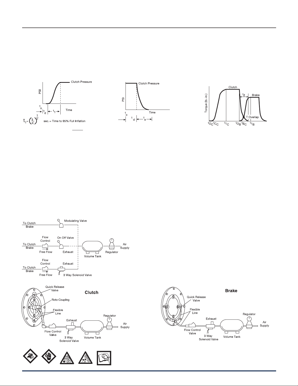
Air System Data
PSI pressure
Inflation
Exhaust
Overlap
Clutch air pressure during inflation can
be closely estimated by the following:
Clutch pressure = P
(inflation)
1
1 – )PSI
1
u
Kt
(
e
This equation is accurate from 5% up
to 95% P
= Line pressure to clutch PSI
P
1
.
1
K and U = coefficients for specific
clutch and air pressure from
Spec i fi ca tion Table
e = Naperian base log
t
= Time at initiation of signal for
o
inflation sec.
t
= Time delay of air system – sec.
d
Clutch air pressure during exhaust
can be closely estimated by the
fol low ing:
Clutch pressure = (P
) (R) (E-t)vPSI
1
(exhaust)
R, E and V = coefficients for specific clutch
and air pressurefrom Spec i fi ca tion
Table
t
= Time to exhaust = E from
e
Spec i fi ca tion Table
t = Time variable – seconds. In the ex -
haust equa tion “t” cannot exceed
the value of “E” sec.
Shown are some of the air systems used
on Wichita clutches. These systems are
ac cept able for remote op er a tion where
clutch reaction time is not important.
Faster clutch re ac tion time is ac com
plished as in di cat ed in the
di a gram by lo cat ing the flow
control valve, if re quired,
and the so le noid valve as
close as possible to the
roto-cou pling. Where
clutches are located on long shafts, the
use of quick release valves on the clutch
will fa cil i tate faster clutch response.
A typical clutch-brake torque curve for
a single backshaft press (cyclic ap pli ca tion) would appear as shown below.
Time (sec.)
t
= time at which disengaged clutch
O
c
receives signal
t
= time of clutch en gage ment
C
c
= time of clutch full inflation
t
1
c
= time at which disengaged brake
t
O
B
receives signal
t
= time of brake engagement
B
c
= time of brake full exhaust
t
1
B
t2 = overlap time at which clutch and
brake are both engaged
28 Wichita Clutch 800-964-3262
P-1100-WC 1/12
Page 8

Air Tube Disc Clutches and Brakes
Low Inertia and Very Low Inertia Clutches and Brakes
Inflation Coefficients
Model Inflation Coefficients Operating Air Pressure
Size 50 PSI 75 PSI 100 PSI
ATD- K U K U K U
108 15,800 2.2 7,100 2 265 1.2
208 15,800 2.2 7,100 2 265 1.2
111 890 1.7 880 1.6 5,100 2.2
211 890 1.7 880 1.6 5,100 2.2
114 980 2.3 980 2.3 980 2.3
214 980 2.3 980 2.3 980 2.3
118 9,600 3.1 1,560 2.4 9,600 3.1
218 9,600 3.1 1,560 2.4 9,600 3.1
124H 145 1.8 90 1.6 87 1.6
224H 145 1.8 90 1.6 87 1.6
130H 185 2 150 2 93 1.8
230H 185 2 150 2 93 1.8
136 170 2 250 2.2 160 2
236 170 2 250 2.2 160 2
142 115 2 125 2 111 2
242 115 2 125 2 111 2
148 25 1.6 22 1.6 26 1.8
248 25 1.6 22 1.6 26 1.8
260 28 1.8 22 1.8 20 1.8
360 28 1.8 22 1.8 20 1.8
B
Exhaust Coefficients
Model Exhaust Coefficients Operating Air Pressure
Size 50 PSI 75 PSI 100 PSI
ATD- R E V R E V R E V
108 60 .016 1.0 525 .02 1.6 240 .02 1.4
208 60 .016 1.0 525 .02 1.6 240 .02 1.4
111 1,000 .032 2 8,200 .04 2.8 4,930 .048 2.8
211 1,000 .032 2 8,200 .04 2.8 4,930 .048 2.8
114 720 .072 2.5 800 .069 2.5 1,840 .082 3
214 720 .072 2.5 800 .069 2.5 1,840 .082 3
118 44 .068 1.4 40 .072 1.4 34 .08 1.4
218 44 .068 1.4 40 .072 1.4 34 .08 1.4
124H 360 .096 2.5 240 .112 2.5 270 .136 2.8
224H 360 .096 2.5 240 .112 2.5 270 .136 2.8
130H 120 .104 2.1 140 .128 2.4 146 .158 2.7
230H 120 .104 2.1 140 .128 2.4 146 .158 2.7
136 124 .112 2.2 92 .128 2.2 76 .152 2.3
236 124 .112 2.2 92 .128 2.2 76 .152 2.3
142 132 .12 2.3 89 .144 2.3 61 .168 2.3
242 132 .12 2.3 89 .144 2.3 61 .168 2.3
148 20 .224 2 20 .256 2.2 19 .308 2.5
248 20 .224 2 20 .256 2.2 19 .308 2.5
260 24 .264 2.4 10 .367 2.3 9.9 .352 2.2
360 24 .264 2.4 10 .367 2.3 9.9 .352 2.2
P-1100-WC 1/12
Wichita Clutch 800-964-3262 29
Page 9

Air Tube Disc Clutches and Brakes
Low Inertia Clutches
Sizes 8-36
30 Wichita Clutch 800-964-3262
P-1100-WC 1/12
Page 10

Air Tube Disc Clutches and Brakes
Low Inertia Clutches
Sizes 8-36
Dimensions: inches (mm)
Model AB C DE FGH
Size ATD- Hole Circle Pilot
LIC 108 12.13 11.125 8.375 / 8.378 11.13 6.31 (160.3) 2.00 (50.8) .25 (6.4) 4.56 (115.8)
LIC 208 (308.1) (282.58) (212.73 / 212.80) (282.7) 7.69 (195.3) 3.25 (82.6) .31 (7.9) 5.94 (150.9)
LIC 111 16.00 14.750 11.375 / 11.378 14.75 7.25 (184.2) 2.75 (69.9) .13 (3.3) 5.50 (139.7)
LIC 211 (406.4) (374.65) (288.93 / 289.00) (374.7) 9.00 (228.6) 4.38 (111.3) .25 (6.4) 7.25 (184.2)
LIC 114 18.75 17.500 14.375 / 14.378 17.50 7.56 (192.0) 3.75 (95.3) .13 (3.3) 6.06 (153.9)
LIC 214 (476.3) (444.50) (365.13 / 365.20) (444.5) 9.38 (238.3) 4.50 (114.3) .38 (9.7) 7.88 (200.2)
LIC 116
LIC 216 9.75 (247.7) 4.75 (120.7) .38 (9.7) 8.25 (209.6)
LIC 316
LIC 118
LIC 218 10.13 (257.3) 4.75 (120.7) .44 (11.2) 8.63 (219.2)
LIC 318
LIC 121
LIC 221 10.94 (277.9) 5.13 (130.3) .63 (16.0) 9.44 (239.8)
LIC 321
LIC 124H
LIC 224H 11.38 (289.1) 5.13 (130.3) .75 (19.1) 9.88 (251.0)
LIC 324H
LIC 127
LIC 227 11.88 (301.8) 6.88 (174.8) 10.38 (263.7)
LIC 327
LIC 130H
LIC 230H 15.94 7.13 (181.1) 1.88 (47.8) 11.69 (296.9)
LIC 330H
LIC 136
LIC 236 16.63 (422.4) 9.00 (228.6) .63 (16.0) 12.75 (323.9)
LIC 336
21.25 20.000 16.250 / 16.253 20.00
(539.8) (508.00) (412.75 / 412.83) (508.0)
23.25 22.000 18.250 / 18.253 22.00
(590.6) (558.80) (463.55 / 463.63) (558.8)
27.00 25.500 21.375 / 21.378 24.88
(685.8) (647.70) (542.93 / 543.00) (632.0)
30.00 28.750 24.375 / 24.378 29.00
(762) (730.25) (619.13 / 619.20) (736.6)
32.75 31.500 27.375 / 27.378 31.00
(831.9) (800.10) (695.33 / 695.40) (787.4)
37.00 35.500 30.375 / 30.3783 34.75
(939.8) (901.70) (771.53 / 771.60) (882.7)
43.50 42.000 36.375 / 36.378 41.00
(1,104.9) (1,066.80) (923.93 / 924.00) (1,041.4)
7.81 (198.4) 4.00 (101.6) 6.31 (160.3)
11.69 (296.9) 6.63 (168.4) 10.19 (258.8)
8.19 (208.0) 4.00 (101.6) 6.69 (169.9)
12.13 (308.1) 6.50 (165.1) 10.63 (270.0)
8.88 (225.6) 4.00 (101.6) .75 (19.1) 7.38 (187.5)
13.25 (336.6) 7.13 (181.1) .75 (19.1) 11.75 (298.5)
9.13 (231.9) 4.00 (101.6) .69 (17.5) 7.63 (193.8)
13.75 (349.3) 7.50 (190.5) .75 (19.1) 12.25 (311.2)
9.38 (238.3) 4.50 (114.3)
————
12.5 5.00 (127.0) .63 (16.0) 8.25 (209.6)
————
12.94 (328.7) 5.63 (143.0) 9.44 (239.8)
19.88 (505.0) 12.38 (314.5) 16.38 (416.1)
.75 (19.1)
7.88 (200.2)
B
Dimensions: inches (mm)
Model IJ L M NQR S U
Size ATD- No. - Size No. - Size Min. Max.
LIC 108 1.78 (45.2) .25
LIC 208 1.88 (47.8) (6.4) (136.7) (88.9) (12.7) (25) (50.8)
LIC 111
LIC 211 (9.7) 21/32 (16.7) (177.8) (101.6) (16.0) (25) (63.5)
LIC 114 1.44 (36.6) .38
LIC 214 2.13 (54.1) (9.7) (239.8) (139.7) (16.0) (35.1) (88.9)
LIC 116 1.13 (28.7)
LIC 216 2.31 (58.7) 12 - 21/32 (16.7) 2 - 1/2 NPT 1"-14NF
LIC 316 2.31 (58.7)
LIC 118 1.25 (31.8)
LIC 218 2.50 (63.5) 12 - 21/32 (16.7) 3 - 1/2 NPT 1"-14NF
LIC 318 2.75 (69.9)
LIC 121 1.63 (41.4)
LIC 221 2.68 (68.1) 12 - 21/32 (16.7) 3 - 1/2 NPT 1"-14NF
LIC 321 2.75 (69.9)
LIC 124H 1.75 (44.5)
LIC 224H 2.94 (74.7) 12 - 21/32 (16.7) 3 - 1/2 NPT 1"-14NF
LIC 324H 2.88 (73.2)
LIC 127 1.38 (35.1) .25
LIC 227 1.50 (38.1) (6.4) 16 - 21/32 (16.7) 3 - 1/2 NPT 1"-14NF
LIC 327 ——
LIC 130H 1.81 (46.0)
LIC 230H 1.88 (47.8) 18 - 25/32 (19.8) 4 - 1/2 NPT 1" NPT
LIC 330H —
LIC 136 1.38 (35.1)
LIC 236 1.63 (41.4) 18 - 25/32 (19.8) 4 - 1/2 NPT 1" NPT
LIC 336 1.75 (44.5)
2.00 (50.8)
.38
.38 10.50 6.00 .63 1.38 4.00
(9.7) (266.7) (152.4) (16.0) (35.1) (101.6)
.38 12.50 7.00 .63 2.00 4.75
(9.7) (317.5) (177.8) (16.0) (50.8) (120.7)
.31 14.50 9.00 .75 2.00 6.00
(7.9) (368.3) (228.6) (19.1) (50.8) (152.4)
.25 14.50 9.00 .75 2.00 6.00
(6.4) (368.3) (228.6) (19.1) (50.8) (152.4)
.25 19.25 10.00 .75 2.50 7.25
(6.4) (489) (254) (19.1) (63.5) (184.2)
.25 23.63 12.00 .88 6.00 9.00
(6.4) (600.2) (304.8) (22.4) (152.4) (228.6)
6 - 17/32 (13.5)
11/16 (17.5) 7.00 4.00 .63
6 -
8 - 21/32 (16.7)
5.38 3.50 .50
9.44 5.50 .63
16.25 9.00 .75 2.50 6.50
(412.8) (228.6) (19.1) (63.5) (165.1)
2 - 1/2 NPT 1"-14NF
2 - 1/2 NPT 1"-14NF
2 - 1/2 NPT 1"-14NF
1.00 2.00
1.00 2.50
1.38 3.50
Note: For mounting, use socket head capscrews conforming to the ASTM-574-97a. (Consult factory for drawing before final layout.)
P-1100-WC 1/12
Wichita Clutch 800-964-3262 31
Page 11

Air Tube Disc Clutches and Brakes
Low Inertia Clutches
Sizes 6, 42-60
Size 6
32 Wichita Clutch 800-964-3262
Size 42-60
P-1100-WC 1/12
Page 12

Air Tube Disc Clutches and Brakes
Low Inertia Clutches
Sizes 6, 42-60
Dimensions: inches (mm)
Model AB C DE FGH
Size ATD- Hole Circle Pilot
LIC 106 8.75 8.000 7.377 / 7.379 8.81 5.19 (131.8) 2.00 (50.8) 0.00 (0.0) 3.75 (95.3)
LIC 206 (222.3) (203.20) (187.38 / 187.43) (223.8) 6.43 (163.3) 3.25 (82.6) 0.06 (1.5) 5.00 (127.0)
LIC 142 52.00 49.250 44.625 / 44.628 49.00 10.81 (274.6) 5.63 (143.0)
LIC 242 (1,320.8) (1,250.95) (1,133.48 / 1,133.55) (1,244.6) 14.56 (369.8) 7.50 (190.5) 13.5 (342.9)
LIC 148 61.00 58.000 52.000 / 52.005 56.75 14.69 (373.1) 6.00 (152.4) 0.00 (0.0) 10.69 (271.5)
LIC 248 (1,549.4) (1,473.20) (1,320.80 / 1,320.93) (1,441.5) 19.07 (484.4) 8.75 (222.3) 1.00 (25.4) 15.07 (382.8)
1
LIC 260
LIC 360
LIC 460
70.50 66.500 62.750 / 62.760 70.50
1
(1,790.7) (1,689.10) (1,593.85 / 1,594.10) (1,790.7)
1
20.30 (515.6) 9.38 (238.3) 0.25 (6.4) 17.99 (456.9)
22.00 (558.8) 12.25 (311.2) 0.00 (0.0) 19.63 (498.6)
28.25 (717.6) 18.63 (473.2) 0.25 (6.4) 27.13 (689.1)
1.00 (25.40)
Dimensions: inches (mm)
Model IJL M NQR S U
Size ATD- No.- Size No. - Size Min. Max.
LIC 106 1.56 (39.6) 0.06
LIC 206 1.50 (38.1) (1.5) (106.4) (68.3) (14.2) (15.2) (50.8)
LIC 142 1.75 (44.5) 0.25
LIC 242 3.63 (92.2) (6.4) (749.3) (457.2) (38.1) (203.2) (355.6)
LIC 148 3.69 (93.7) 0.25
LIC 248 4.32 (109.7) (6.4) (812.8) (654.1) (38.1 (254.0) (457.2)
1
LIC 260
LIC 360
LIC 460
6.17 (156.7)
1
5.19 (131.8) 24 - 4.5"NC — 6 - 1/2 NPT 2"-12NF
1
6.38 (162.1)
0.25 36.00 27.00 11.00 19.00
(6.4) (914.4) (685.8) (279.4) (482.6)
4 - 0.34 (8.6)
24 - 1.06 (26.9)
24 - 1.06 (26.9)
4.19 2.69 0.56
29.50 18.00 1.50
32.00 25.75 1.50)
— 5/8"-11NF
4 - 1/2 NPT 1.5"-12NF
4 - 1/2 NPT 1" NPT
9.75 (247.7)
0.60 2.00
8.00 14.00
10.00 18.00
B
1
Less backplate.
NOTE: For mounting, use socket head capscrews conforming to the ASTM-574-97a.
(Consult factory for drawing before final layout.)
P-1100-WC 1/12
Wichita Clutch 800-964-3262 33
Page 13

Air Tube Disc Clutches and Brakes
Low Inertia Clutch Air Hose Kits
Size Part Number
8" 8-908-812-200-5
8-908-821-201-5 QRV
11" 8-911-812-201-5
8-911-821-201-5 QRV
14" 8-914-812-200-5
8-914-821-200-5 QRV
Size Part Number
18" 8-918-812-301-5
8-918-821-300-5 QRV
24"H 8-924-812-300-5
8-924-821-301-5 QRV
Air hose kits contain all nec es sary parts
(fittings, hoses and extensions) to
com plete ly plumb the clutch air system.
Optional Quick Release Valves
can replace elbows on most
units (see page 35).
Roto-couplings (see page 35).
Size Part Number
30" 8-930-812-400-5
8-930-821-400-5 QRV
36" 8-936-821-400-5 QRV
42" 8-942-821-400-5 QRV
48" 8-948-821-400-5 QRV
Size Part Number
60" 8-960-800-500-7 QRV
34 Wichita Clutch 800-964-3262
P-1100-WC 1/12
Page 14

Air Tube Disc Clutches and Brakes
1/2" NPT (for Optional Mufer 4-263-605-002-0)
Quick Release Valve
8-263-610-011-1 7/8" – 14 Thread
8-263-610-021-1 1/2" NPT
4-263-605-002-0 Optional Muffler
The Wichita Springless Quick Release Valve
discharges twice as fast as any other valve
tested in our laboratory and is four to five times
faster than some common makes of valves.
This valve will close and seal with less than 20
lbs. pressure. Most others require 25 to 30 lbs. to
definitely seal. In actual tests, the Wichita Valve
made many hundreds of thousands of
engagements and dis en gage ments before the
slightest leak occurred, or any parts needed re place ment. Other valves which were tested
required major re place ment in fewer than 20,000
cycles.
Quality Material
Body and Cap: High strength aluminum alloy
Stem: Molded nylon
Check Valve: Nylon ball
"O" Ring: Neoprene
B
Standard thread arrangement of 1/2" size.
1/2" pipe thread on the tube connection and
choice of 1/2" pipe thread, or stan dard
7/8-14NF thread for flared fitting thread on
inlet connection. (Fits standard No. 10 highpressure hose fitting.)
Roto-couplings
• Long life, no maintenance.
• Felt seal eliminates bearing con tam i na tion.
• Fast, easy installation.
The Wichita Roto-coupling is a device to
connect, or couple, a non-rotating air, gas,
or fluid line to a rotating shaft.
Dimensions: inches
Wichita Part No. AA B C D E F G H Max. RPM
8-240-701-003-1 5/8-18NF 1/4" NPT .40 1.046 2.250 1.500 2.13 3.297 3500
8-240-705-001-1 1"-14 NF 1/2" NPT .75 1.250 3.188 2.500 3.00 4.438 3500
8-240-708-001-1 1"-14 NF 3/4" NPT .75 1.313 4.688 2.875 3.69 5.440 3500
8-240-710-002-1 1-1/2"-12 NF 1" NPT 1.13 1.937 4.875 3.250 3.44 6.812 2500
8-240-712-001-1 2"-12 NF 1-1/2" NPT 1.13 2.813 5.250 4.250 5.38 8.062 2500
8-240-714-001-3 2" NPT 2" NPT 1.50 3.000 7.062 4.625 7.00 10.062 1000
8-240-716-000-3 2-1/2" NPT 2-1/2" NPT 1.88 3.250 9.375 7.000 7.75 12.625 750
P-1100-WC 1/12
Wichita Clutch 800-964-3262 35
Page 15

Air Tube Disc Clutches and Brakes
Low Inertia Brakes
Specifications
Model Slip Torque Capacity Duty Factors Max. Bore
Size Assembly Drawing lb.in. Nm HP/100 RPM Rect. Key
ATD- Number Number 80 PSI 100 PSI 5.5 BAR 7 BAR ABCDin. (mm)
LIB 104 7-004-100-803-0 -100-901-9 800 1,000 90 113 1.6 1.2 0.6 0.3
LIB 204 7-004-200-801-0 B-518 1,600 2,000 90 225 3.2 2.4 1.2 0.6
LIB 106 7-006-100-203-0 -100-901-9 3,160 3,950 340 435 6.2 4.4 2.2 1.1
LIB 206 7-006-200-200-0 D-465 6,320 7,900 680 870 12.5 8.8 4.4 2.2
LIB 108 7-008-100-108-0 -100-900-9 5,600 7,000 620 790 11.1 842
LIB 208 7-008-200-105-0 -200-900-9 11,200 14,000 1,240 1,580 22.2 16 84 2.25 (57)
LIB 308 7-008-300-100-0 D-164 16,800 21,000 1,865 2,375 33.3 24 12 6
LIB 111 7-011-100-107-0 B-105 12,720 15,900 1,400 1,785 25 18 95
LIB 211 7-011-200-102-0 -200-902-9 25,440 31,800 2,800 3,570 50 36 18 10 2.50 (64)
LIB 311 7-011-300-100-0 B-408 38,160 47,700 4,235 5,390 75 54 27 15
LIB 114 7-014-100-102-0 -100-900-9 22,100 27,625 2,435 3,100 44 31 16 8
LIB 214 7-014-200-101-0 -200-902-9 44,200 55,250 4,870 6,200 88 62 32 16 3.50 (89)
LIB 314 7-014-300-102-0 B-288 66,300 82,875 7,355 9,365 132 93 48 24
LIB 116 7-016-100-100-0 D-461 30,270 37,838 3,360 4,275 60 46 24 12
LIB 216 7-016-200-100-0 -200-904-9 60,541 75,676 6,720 8,550 120 92 48 24 4.00 (102)
LIB 316 7-016-300-100-0 -300-900-9 90,811 113,514 10,080 12,825 180 139 72 36
LIB 118 7-018-100-100-0 -100-901-9 51,600 64,500 5,705 7,260 102 75 35 21
LIB 218 7-018-200-100-0 -200-900-9 103,200 129,000 11,410 14,520 204 150 70 42 4.75 (121)
LIB 318 7-018-300-103-0 D-1218 154,840 193,550 17,115 21,780 306 225 105 63
LIB 121 7-021-100-100-0 D-373 69,887 87,359 7,755 9,870 139 107 55 28
LIB 221 7-021-200-100-0 D-267 139,775 174,719 15,510 19,740 277 213 111 55 6.00 (152)
LIB 321 7-021-300-100-0 D-740 209,662 262,078 23,265 29,610 416 320 166 83
LIB 124H 7-025-100-101-0 D-779 122,960 153,700 13,575 17,275 243 180 90 40
LIB 224H 7-025-200-101-0 D-371 245,920 307,400 27,150 34,550 487 360 180 80 6.00 (152)
LIB 324H 7-025-300-201-0 -300-900-9 368,880 461,100 40,725 51,825 729 540 270 120
LIB 127 7-027-100-100-0 D-151 137,509 171,886 15,260 19,420 273 210 109 55
LIB 227 7-027-200-100-0 D-428 275,018 343,773 30,520 38,840 546 420 218 109 6.50 (165)
LIB 327 6-027-300-100-0 D-689 412,527 515,659 45,780 58,260 819 630 327 164
LIB 130H 7-031-100-100-0 B-312 261,600 327,000 29,630 37,710 519 380 190 100
LIB 230H 7-031-200-316-0 B-296 523,200 654,000 59,260 75,420 1,038 760 380 200 7.25 (184)
LIB 330H 7-031-300-304-0 -300-904-9 784,800 981,000 88,890 113,130 1,557 1,140 570 300
LIB 136 7-036-100-100-0 -100-901-9 406,400 508,000 44,920 57,175 805 600 295 165
LIB 236 7-036-200-100-0 D-722 812,800 1,016,000 89,840 114,350 1,610 1,200 590 330 9.00 (229)
LIB 336 6-036-300-100-0 -300-900-9 1,219,200 1,524,000 134,760 171,525 2,415 1,800 885 495
LIB 142 7-042-100-303-0 -100-900-9 580,800 726,000 69,160 81,660 1,150 850 425 235
LIB 242 7-042-200-311-0 -200-901-9 1,162,240 1,452,800 128,320 163,320 2,300 1,700 850 470 14.00 (355)
LIB 342 6-042-300-302-0 -300-303-9 1,742,400 2,178,000 192,480 244,980 3,450 2,550 1,275 705
LIB 148 7-048-100-300-0 -100-900-9 1,122,000 1,402,500 118,800 151,200 2,225 1,600 800 455
LIB 248 7-048-200-300-0 -200-901-9 2,244,000 2,805,000 237,600 302,400 4,450 3,200 1,600 915 18.00 (455)
LIB 348 7-048-300-301-0 -300-900-9 3,366,000 4,207,500 356,400 453,600 6,675 4,800 2,400 1,365
LIB 260 7-060-200-302-0 -200-901-9 4,760,000 5,950,000 473,000 602,000 9,440 5,950 3,470 1,940
LIB 360 7-060-300-301-0 -300-901-9 7,140,000 8,925,000 709,000 902,300 14,160 8,925 5,205 2,910 19.00 (480)
LIB 460 6-060-400-300-0 E-236 14,280,000 17,850,000 946,000 1,204,000 18,880 11,900 6,940 3,880
Maximum Air Pressure is 130 PSI / 9 BAR.
1.00 (25)
2.00 (50)
36 Wichita Clutch 800-964-3262
P-1100-WC 1/12
Page 16

Air Tube Disc Clutches and Brakes
Low Inertia Brakes
Specifications
Recom- Hub & C.P. Airtube
Model mended Balance Reg- High Swept Volume Total Brake Hub & Center Plate
Size Clearance Speed Speed Speed Area in.3(cm3) Wt. Wt. WR2/ J=mr
ATD- in. RPM RPM RPM* in.
LIB 104 1/32
LIB 204 1/16 34 (14.8) (56) 14.0 (6) 3.88 (1.8) 0.04 (0.002)
LIB 106 1/16-3/32
LIB 206 3/32-5/32 78 (30) (195) 40.5 (18) 12.17 (5.5) 0.46 (0.019)
LIB 108 1/16-1/8 56
LIB 208 3/32-5/32 1,675 2,870 4,300* 112 70 (32) 19 (8.6) 1.00 (0.042)
LIB 308 1/8-3/16 168
LIB 111 1/16-1/8 114
LIB 211 3/32-5/32 1,200 2,090 3,125* 228 166 (75) 45 (20.4) 4.50 (0.190)
LIB 311 1/8-3/16 342
LIB 114 1/16-1/8 158
LIB 214 3/32-5/32 950 1,640 2,450* 316 233 (106) 77 (34.9) 11.0 (0.464)
LIB 314 1/8-3/16 474
LIB 116 1/16-1/8 228
LIB 216 3/32-5/32 835 1,430 2,150* 455 326 (148) 106 (48.1) 19.6 (0.826)
LIB 316 1/8-3/16 683
LIB 118 1/16-1/8 264
LIB 218 3/32-5/32 750 1,270 1,910* 528 377 (171) 120 (54.4) 28.8 (1.214)
LIB 318 1/8-3/16 792
LIB 121 3/32-5/32 362
LIB 221 1/8-3/16 650 1,090 1,650* 724 575 (261) 198 (89.8) 61 (2.57)
LIB 321 5/32-7/32 1,086
LIB 124H 3/32-5/32 574
LIB 224H 1/8-3/16 550 950 1,410* 1,148 840 (381) 260 (117.9) 110 (4.6)
LIB 324H 5/32-7/32 1,722
LIB 127 3/32-5/32 730
LIB 227 1/8-3/16 500 850 1,250* 1,460 924 (419) 329 (149.2) 191 (8.1)
LIB 327 5/32-7/32 2,190
LIB 130H 3/32-5/32 827
LIB 230H 1/8-3/16 450 765 1130* 1,654 1,350 (612) 546 (247.7) 370 (15.6)
LIB 330H 5/32-7/32 2,481
LIB 136 3/32-5/32 1,150
LIB 236 1/8 -3/16 375 640 950* 2,300 1,993 (904) 708 (321.1) 725 (30.6)
LIB 336 5/32-7/32 3,450
LIB 142 5/32-7/32 1,400
LIB 242 3/16-1/4 325 545 805* 2,800 2,732 (1,239) 1,197 (543) 1,385 (58)
LIB 342 7/32-9/32 4,200
LIB 148 1/8-1/4 2,010
LIB 248 5/32-7/32 275 475 705* 4,020 4,700 (2,132) 1,942 (881) 3,335 (141)
LIB 348 3/16-5/16 6,030
LIB 260 3/16-5/16 7,230
LIB 360 1/4-3/8 225 380 575* 10,845 11,643 (5,281) 3,870 (1,755) 10,615 (448)
LIB 460 5/16-7/16 14,460
* Consult Factory for Special Assembly Number.
3,325 5,250 5,250*
2,225 3,800 5,700*
2
17 0.9 3.4 11.0 (7) 1.54 (0.7) 0.021 (0.001)
39 1.8 11.9 27.5 (12) 6.40 (2.9) 0.24 (0.010)
New Worn lb. (kg) lb. (kg) lb.ft.2(kgm2)
3.4 18.3
(56) (300)
5.5 30.5
(90) (500)
7.6 42.7
(125) (700)
9.8 56.1
(161) (919)
15.3 85.4
(251) (1,400)
18.3 97.6
(300) (1,599)
29.9 159
(490) (2,606)
29.9 159
(490) (2,606)
58.6 311
(960) (5,096)
110 415
(1,803) (6,801)
128 488
(2,098) (7,997)
217 824
(3,550) (13,500)
513 1,788
(8,407) (29,300)
62 (28) 11 (5.0) 0.54 (0.023)
87 (39) 28 (12.7) 2.00 (0.084)
130 (59) 23 (10.4) 2.30 (0.097)
208 (94) 121 (54.9) 7.00 (0.295)
184 (83) 46 (20.9) 5.7 (0.240)
290 (132) 121 (54.9) 16.7 (0.704)
254 (115) 59 (26.8) 10.2 (0.430)
358 (162) 151 (68.5) 29.6 (1.248)
311 (141) 73 (33.1) 15.0 (0.632)
461 (209) 180 (81.6) 43.2 (1.821)
460 (209) 116 (52.6) 32 (1.35)
723 (328) 312 (141.5) 122 (5.14)
618 (280) 132 (60.0) 56 (2.4)
1,025 (465) 379 (172.0) 160 (6.8)
760 (345) 187 (84.8) 98 (4.1)
1,112 (504) 555 (251.7) 285 (12.0)
972 (441) 298 (135.2) 189 (8.0)
1,751 (794) 810 (367.4) 477 (20.1)
1,388 (630) 461 (209.1) 372 (15.7)
2,610 (1,184) 1,134 (514.4) 1,091 (46.0)
1,967 (892) 680 (308) 705 (30)
3,704 (1,680) 1,324 (601) 1,809 (76)
3,158 (1,432) 1,101 (499) 1,785 (75)
6,540 (2,966) 2,950 (1,338) 4,925 (208)
9,453 (4,288) 2,567 (1,164) 7,077 (298)
14,500 (6,577) 5,700 (2,585) 15,070 (635)
2
B
P-1100-WC 1/12
Wichita Clutch 800-964-3262 37
Page 17

Air Tube Disc Clutches and Brakes
Low Inertia Brakes
Sizes 8-36
38 Wichita Clutch 800-964-3262
P-1100-WC 1/12
Page 18

Air Tube Disc Clutches and Brakes
Low Inertia Brakes
Dimensions: inches (mm)
Sizes 8-36
Model BC
Size ATD- A Hole Circle Pilot DF GH
LIB 108 12.13 11.125 8.375 / 8.378 11.13 2.00 (50.8) .25 4.56 (115.8)
LIB 208 (308.1) (282.58) (212.73 / 212.80) (282.7) 3.25 (82.6) (6.4) 5.94 (150.9)
LIB 111 16.00 14.750 11.375 / 11.378 14.75 2.75 (69.9) .13 (3.3) 5.44 (138.2)
LIB 211 (406.4) (374.65) (288.93 / 289.00) (374.7) 4.38 (111.3) .25 (6.4) 7.19 (182.6)
LIB 114 18.75 17.500 14.375 / 14.378 17.50 3.75 (95.3) .13 (3.3) 6.06 (153.9)
LIB 214 (476.3) (444.50) (365.13 / 365.20) (444.5) 4.50 (114.3) .38 (9.7) 8.00 (203.2)
LIB 116
LIB 216 4.75 (120.7) 8.25 (209.6)
LIB 316
LIB 118
LIB 218 4.75 (120.7) 8.63 (219.2)
LIB 318
LIB 121
LIB 221 5.13 (130.3) 9.31 (236.5)
LIB 321
LIB 124H
LIB 224H 5.13 (130.3) .75 (19.1) 9.94 (252.5)
LIB 324H
LIB 127
LIB 227 6.88 (174.8) 10.38 (263.7)
LIB 327
LIB 130H
LIB 230H 7.13 (181.1) 1.88 (47.8) 11.81 (300.0)
LIB 330H
LIB 136 43.50 42.000 36.375 / 36.378 41.00 5.63 (143.0) 0.63 9.50 (241.3)
LIB 236 (1,104.9) (1,066.80) (923.93 / 924.00) (1,041.4) 9.00 (228.6) (16.0) 12.88 (327.2)
21.25 20.000 16.250 / 16.253 20.00
(539.8) (508.00) (412.75 / 412.83) (508.0)
23.25 22.000 18.250 / 18.253 22.00
(590.6) (558.80) (463.55 / 463.63) (558.8)
27.00 25.500 21.375 / 21.378 24.88
(685.8) (647.70) (542.93 / 543.00) (632.0)
30.00 28.750 24.375 / 24.378 29.00
(762) (730.25) (619.13 / 619.20) (736.6)
32.75 31.500 27.375 / 27.378 31.00
(831.9) (800.10) (695.33 / 695.40) (787.4)
37.00 35.500 30.375 / 30.378 34.75
(939.8) (901.70) (771.53 / 771.60) (882.7)
4.00 (101.6)
6.63 (168.4)
4.00 (101.6)
6.50 (165.1)
4.00 (101.6)
7.13 (181.1)
4.00 (101.6) .69 (17.5) 7.63 (193.8)
7.50 (190.5) .75 (19.1) 12.25 (311.2)
4.50 (114.3)
———
5.00 (127.0) .63 (16.0) 8.38 (212.9)
11.88 (301.8) .63 (16.0) 15.31 (388.9)
0.38
(9.7)
0.44
(11.2)
.75
(19.1)
0.75 (19.1)
6.31 (160.3)
10.19 (258.8)
6.69 (169.9)
10.63 (270.0)
7.38 (187.5)
11.75 (298.5)
7.88 (200.2)
B
Dimensions: inches (mm)
Model LRU
Size ATD- J No. - Size MNQNo. - Size T Min. Max.
LIB 108 0.25
LIB 208 (6.4) (136.7) (88.9) (12.7) (25) (50.8)
LIB 111 0.38
LIB 211 (9.7) 11/16 (17.5) (177.8) (101.6) (16.0) (25) (63.5)
LIB 114 0.38
LIB 214 (9.7) (239.8) (139.7) (16.0) (35.1) (88.9)
LIB 116
LIB 216 12 - 21/32 (16.7) 2 - 1/2 NPT 6.13
LIB 316
LIB 118
LIB 218 12 - 21/32 (16.7) 3 - 1/2 NPT 7.75
LIB 318
LIB 121
LIB 221 12 - 21/32 (16.7) 3 - 1/2 NPT 9.25
LIB 321
LIB 124H
LIB 224H 12 - 21/32 (16.7) 3 - 1/2 NPT 13.25
LIB 324H
LIB 127 0.25
LIB 227 (6.4) 16 - 21/32 (16.7) 3 - 1/2 NPT 13.25
LIB 327 —
LIB 130H
LIB 230H 18 - 25/32 (19.8) 4 - 1/2 NPT 15.00
LIB 330H
LIB 136 0.25
LIB 236 (6.4) 25/32 (19.8) (600.2) (304.8) (22.4) (152.4) (228.6)
0.38 10.50 6.00 0.63 1.38 4.00
(9.7) (266.7) (152.4) (16.0) (35.1) (101.6)
0.38 12.50 7.00 0.63 2.00 4.75
(9.7) (317.5) (177.8) (16.0) (50.8) (120.7)
0.31 14.50 9.00 .75 2.00 6.00
(7.9) (368.3) (228.6) (19.1) (50.8) (152.4)
0.25 14.50 9.00 .75 2.00 6.00
(6.4) (368.3) (228.6) (19.1) (50.8) (152.4)
0.25 19.25 10.00 .75 2.50 7.25
(6.4) (489) (254) (19.1) (63.5) (184.2)
6 - 17/32 (13.5)
21/32 (16.7) 7.00 4.00 0.63
6 -
8 - 21/32 (16.7)
13/16 (20.6) 23.63 12.00 .88
18 -
5.38 3.50 0.50
9.44 5.50 0.63
16.25 9.00 .75 2.50 6.50
(412.8) (228.6) (19.1) (63.5) (165.1)
2 - 1/2 NPT 2.25
2 - 1/2 NPT 3.25
2 - 1/2 NPT 5.06
4 - 1/2 NPT 22.75
1.00 2.00
1.00 2.50
1.38 3.50
6.00 9.00
Note: For mounting, use socket head capscrews conforming to the ASTM-574-97a.
(Consult factory for drawing before final layout.)
P-1100-WC 1/12
Wichita Clutch 800-964-3262 39
Page 19

Air Tube Disc Clutches and Brakes
Low Inertia Brakes
Sizes 6, 42-60
Size 6
40 Wichita Clutch 800-964-3262
Sizes 42-60
P-1100-WC 1/12
Page 20

Air Tube Disc Clutches and Brakes
Low Inertia Brakes
Sizes 6, 42-60
Dimensions: inches (mm)
Model BC
Size ATD- A Hole Circle Pilot DFGH
LIB 106 8.75 8.000 7.377 / 7.379 8.81 2.00 (50.8) 0.00 (0.0) 3.75 (95.3)
LIB 206 (222.3) (203.20) (187.38 / 187.43) (223.8) 3.25 (82.6) 0.06 (1.5) 5.00 (127.0)
LIB 142 52.00 49.250 44.625 / 44.628 49.00 5.63 (143.0)
LIB 242 (1,320.8) (1,250.95) (1,133.48 / 1,133.55) (1,244.6) 7.50 (190.5) 13.5 (342.9)
LIB 148 61.00 58.000 52.000 / 52.005 56.75 6.00 (152.4) 0.00 (0.0) 10.69 (271.5)
LIB 248 (1,549.4) (1,473.20) (1,320.80 / 1,320.93) (1,441.5) 8.75 (222.3) 1.00 (25.4) 15.06 (382.5)
LIB 260 70.50 74.500 60.000 / 59.990 70.50 9.38 (238.3)
LIB 360 (1,790.7) (1,892.30) (1,524.0 / 1,523.7) (1,790.7) 12.25 (311.2) 22.88 (581.2)
1.00 (25.40)
3.50 (88.9)
Dimensions: inches (mm)
Model LRU
Size ATD- J No.- Size MNQNo. - Size T Min. Max.
LIB 106 0.06
LIB 206 (1.5) (106.4) (14.2) (50.8) (15.2) (50.8)
LIB 142 0.25
LIB 242 (6.4) (749.3) (38.1) (606.6) (203.2) (355.6)
LIB 148 0.25
LIB 248 (6.4) (812.8) (38.1) (641.4) (254.0) (457.2)
LIB 260 0.38
LIB 360 (9.5) (901.7) 28.15 (715.0) (797.6) (723.9) (279.4) (482.6)
Note: For mounting, use socket head capscrews conforming to the ASTM-574-97a.
(Consult factory for drawing before final layout.)
4 - 0.34 (8.6)
24 - 1.06 (26.9)
24 - 1.06 (26.9)
24 - 2.06 (52.3)
4.19
29.50
32.00
35.50 27.00 (685.8) 3.25
2.69 (68.3)
18.00 (457.2)
25.75 (654.1)
0.56
1.50
1.50
2 - 1/4 NPT
4 - 1/2 NPT
4 - 1/2 NPT
6 - 1/2 NPT
23.88 8.00 14.00
25.25 10.00 18.00
9.75 (247.7)
B
21.25 (539.8)
2.00 0.60 2.00
28.5 11.00 19.00
P-1100-WC 1/12
Wichita Clutch 800-964-3262 41
Page 21

Air Tube Disc Clutches and Brakes
Brake Air Hose Kits
Model Part Number
8" 8-908-912-100-5
8-908-924-100-5 QRV
Model Part Number
6" 8-906-912-200-4
8-906-931-201-5 QRV
8" 8-908-913-200-5
8-908-931-200-5 QRV
11" 8-911-913-200-5
8-911-931-200-5 QRV
14" 8-914-913-200-5
8-914-921-200-5 QRV
16" 8-916-913-200-5
8-916-921-200-5 QRV
Model Part Number
18" 8-918-912-200-5
8-918-931-200-5 QRV
21" 8-921-913-200-5
8-921-931-200-5 QRV
24" 8-924-913-200-5
8-924-931-200-5 QRV
27" 8-927-913-200-5
8-927-921-200-5 QRV
Air hose kits contain all
nec es sary parts (fittings, hoses
and extensions) to com plete ly
plumb the brake air system.
Optional Quick Release Valves
can replace elbows on most
units (see page 35).
Roto-couplings
(see page 35).
Model Part Number
30" 8-930-913-400-5
8-930-931-400-5 QRV
36" 8-936-913-400-6
8-936-931-400-6 QRV
42" 8-942-913-400-6
8-924-931-400-6 QRV
48" 8-948-912-400-6
8-948-923-400-6 QRV
42 Wichita Clutch 800-964-3262
Model Part Number
60" 8-960-912-500-5
8-960-923-400-6 QRV
P-1100-WC 1/12
Page 22

Air Tube Disc Clutches and Brakes
Low Inertia Clutches and Brakes
Component Parts
3
2
4
1
6
B
7
8
7
6
20
19
10
11
1. Hub
2. Demountable Back Plate
3. Socket Head Capscrews
4. Ring
6. Grooved Friction Disc
(grooved on one side)
7. Center Plate
8. Grooved Friction Disc
(grooved on both sides)
12
13
14
10. Pressure Plate
11. Airtube
12. Shims
13. Airtube Holding Plate
14. Socket Head Capscrews
19. Pressure Plate Lugs
20. Hex Head Capscrews
24
21
22
21. Release Springs
22. Flexloc Nuts
23. Roto-coupling
24. “O” Ring
25. Snap Ring
23
25
P-1100-WC 1/12
Wichita Clutch 800-964-3262 43
 Loading...