

Page 1
Industrial Clutch Products
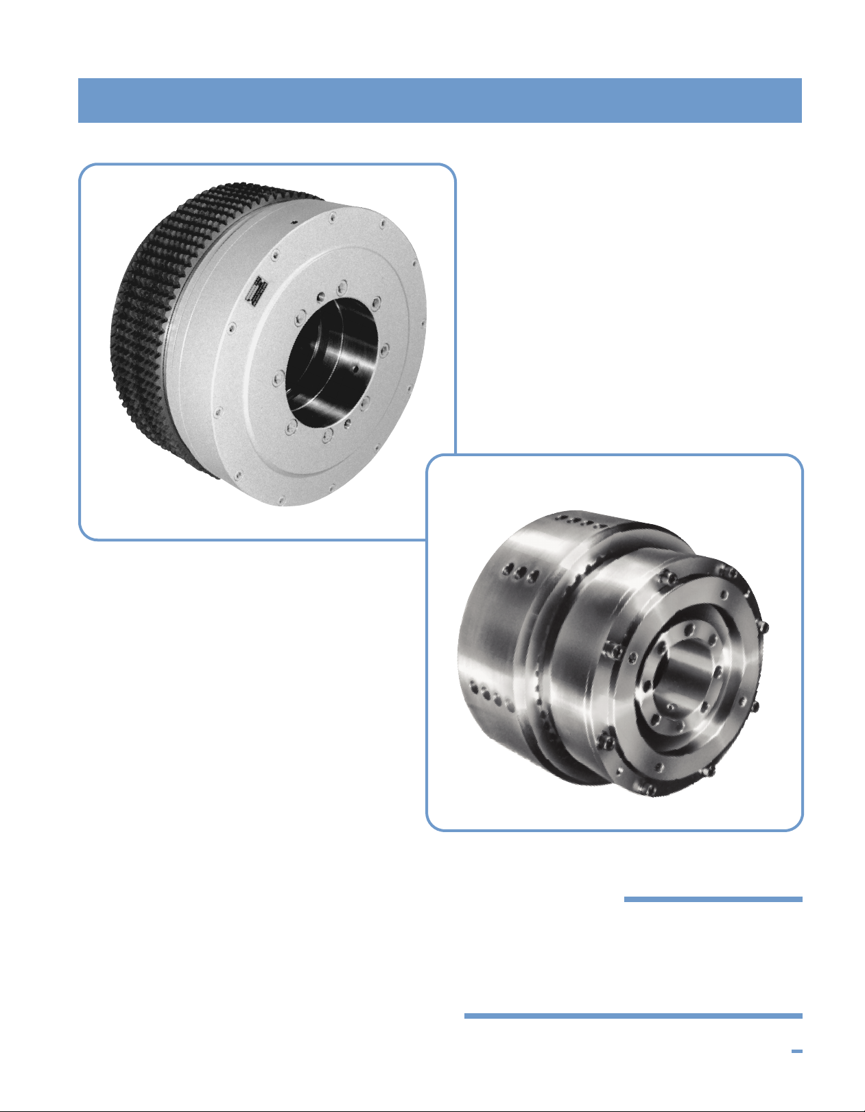
MODEL HC
Air or Hydraulically
Actuated Clutches
I N D U S T R I A L C L U T C H P R O D U C T S 78
Page 2
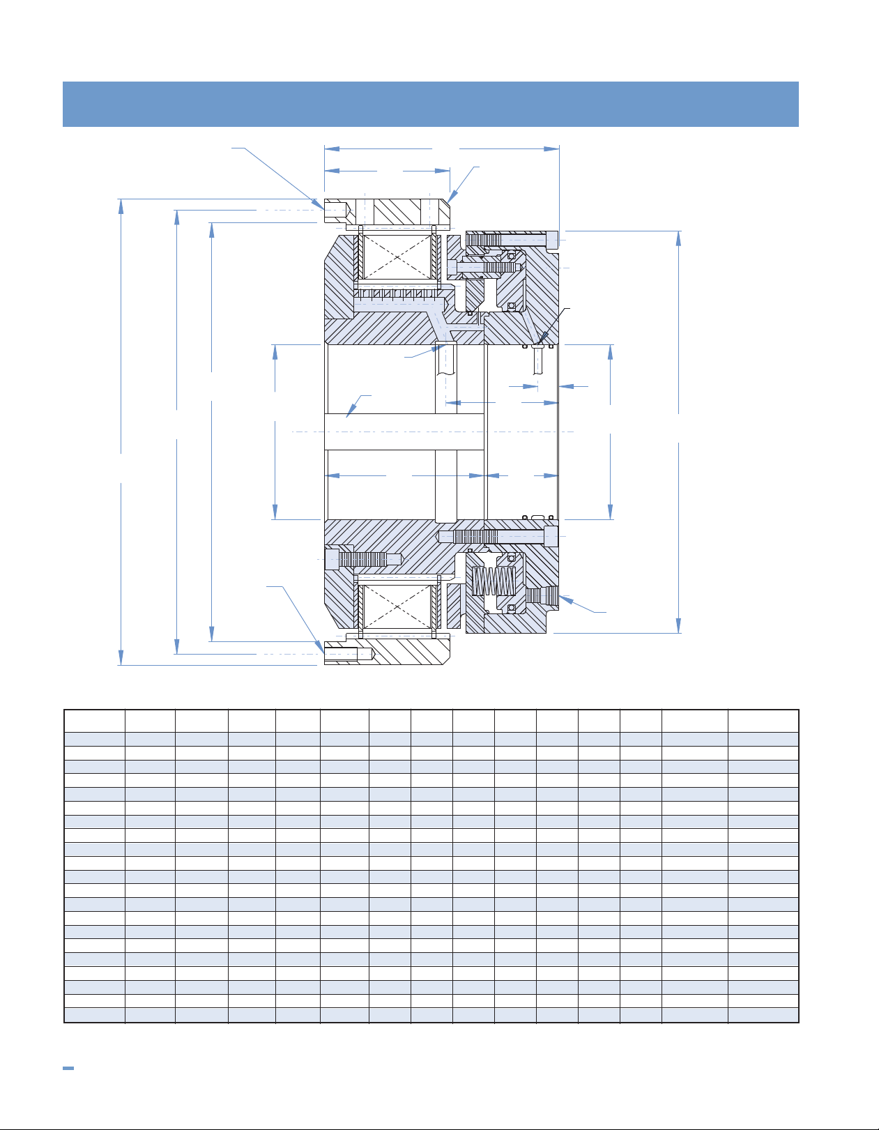
Model HC
D
A
B
C
D
E
H
I
F
JK
G
M
N
L
COME
HOME
FEATURE
ACTUATION
OIL INLETS
COOLING
OIL INLETS
MAX.
MAX.
MAX.
K'W'Y.
+.000"
-.003"
+.003"
-.000"
OPTIONAL
DRIVE RING
DIMENSIONAL DATA All dimensions in inches
Clutch
Model
HC-8-6 10.124 9.4375 8.750 3.000 8.31 3.50 0.51 6.35 2.68 3.81 2.57 0.75 (12) - M10 (4) - .375
HC-8-8 10.124 9.4375 8.750 3.000 8.31 3.50 0.51 6.95 3.28 4.40 2.57 0.75 (12) - M10 (4) - .375
HC-8-10 10.124 9.4375 8.750 3.000 8.31 3.50 0.51 7.55 3.88 5.00 2.57 0.75 (12) - M10 (4) - .375
HC-10-6 11.749 11.063 10.375 4.000 9.81 3.63 0.56 6.54 2.97 4.24 2.38 1.00 (12) - M10 (4) - .500
HC-10-8 11.749 11.063 10.375 4.000 9.81 3.63 0.56 7.25 3.61 4.88 2.38 1.00 (12) - M10 (4) - .500
HC-10-10 11.749 11.063 10.375 4.000 9.81 3.63 0.56 7.89 4.25 5.52 2.38 1.00 (12) - M10 (4) - .500
HC-13-6 15.998 15.250 14.375 6.000 13.81 4.63 0.72 8.09 3.58 4.77 3.32 1.25 (12) - M12 (4) - .500
HC-13-8 15.998 15.250 14.375 6.000 13.81 4.63 0.72 8.80 4.30 5.48 3.32 1.25 (12) - M12 (4) - .500
HC-13-10 15.998 15.250 14.375 6.000 13.81 4.63 0.72 9.52 5.02 6.20 3.32 1.25 (12) - M12 (4) - .500
HC-15-6 18.373 17.375 16.375 6.500 15.75 4.43 0.78 9.06 4.37 5.74 3.31 1.50 (12) - M16 (4) - .625
HC-15-8 18.373 17.375 16.375 6.500 15.75 4.43 0.78 10.00 5.31 6.68 3.31 1.50 (12) - M16 (4) - .625
HC-15-10 18.373 17.375 16.375 6.500 15.75 4.43 0.78 10.94 6.25 7.62 3.31 1.50 (12) - M16 (4) - .625
HC-16-6 19.998 19.000 18.000 7.500 17.25 5.11 1.38 9.29 4.37 5.75 3.54 1.50 (12) - M16 (4) - .625
HC-16-8 19.998 19.000 18.000 7.500 17.25 5.11 1.38 10.23 5.31 6.69 3.54 1.50 (12) - M16 (4) - .625
HC-16-10 19.998 19.000 18.000 7.500 17.25 5.11 1.38 11.17 6.25 7.63 3.54 1.50 (12) - M16 (4) - .625
HC-18-6 21.998 20.750 19.500 8.000 18.63 5.50 1.50 10.96 5.82 7.13 3.81 1.50 (12) - M20 (4) - .750
HC-18-8 21.998 20.750 19.500 8.000 18.63 5.50 1.50 12.23 7.10 8.41 3.81 1.50 (12) - M20 (4) - .750
HC-18-10 21.998 20.750 19.500 8.000 18.63 5.50 1.50 13.51 8.38 9.69 3.81 1.50 (12) - M20 (4) - .750
HC-20-6 24.998 23.750 22.500 9.000 20.63 6.50 1.75 12.04 6.19 7.66 4.37 1.50 (12) - M20 (4) - .750
HC-20-8 24.998 23.750 22.500 9.000 20.63 6.50 1.75 13.32 7.47 8.94 4.37 1.50 (12) - M20 (4) - .750
HC-20-10 24.998 23.750 22.500 9.000 20.63 6.50 1.75 14.60 8.75 10.22 4.37 1.50 (12) - M20 (4) - .750
NOTES: 1.) Use certified drawing dimensions only for final layouts.
2.) DXF and IGES files available upon request.
79 I N D U S T R I A L C L U T C H P R O D U C T S
ABCDEFGHIJKL M N
3.) Dimensions subject to change without notice.
4.) All threaded fasteners are metric.
Page 3

OPERATIONAL DATA
Model HC
Clutch Static Dynamic Act. Vol. Weight Weight WR2Outer WR2Inner Maximum
odel Torque (lb.-in.) Torque (lb.-in.) (in.
M
HC-8-6 55000 39285 4.37 5.8 60.6 0.54 3.79 2600
HC-8-8 70000 50000 4.37 7.7 65.3 0.72 4.04 2600
HC-8-10 85000 60715 4.37 9.7 70.0 0.90 4.29 2600
C-10-6 75000 53570 7.3 7.8 83.7 1.03 7.50 2200
H
C-10-8 100000 71430 7.3 10.4 90.7 1.38 8.06 2200
H
C-10-10 125000 89285 7.3 13.0 97.6 1.72 8.60 2200
H
HC-13-6 200000 142860 14.0 16.3 195.7 4.3 35.9 1700
HC-13-8 275000 196430 14.0 21.7 212.1 5.8 38.4 1700
HC-13-10 350000 250000 14.0 27.1 227.4 7.2 40.8 1700
HC-15-6 325000 232140 19.0 34.0 291.0 11.0 67.0 1450
C-15-8 425000 303570 19.0 45.0 316.0 15.0 72.0 1450
H
C-15-10 525000 375000 19.0 57.0 341.0 19.0 77.0 1450
H
C-16-6 450000 321430 24.0 40.0 357.0 16.0 103.0 1300
H
C-16-8 600000 428570 24.0 54.0 387.0 22.0 110.0 1300
H
HC-16-10 750000 535715 24.0 67.0 417.0 27.0 118.0 1300
HC-18-6 570000 407140 31.0 63.0 494.0 30.0 164.0 1200
HC-18-8 700000 500000 31.0 84.0 544.0 40.0 179.0 1200
HC-18-10 950000 678570 31.0 105.0 594.0 50.0 194.0 1200
HC-20-6 765000 546430 51.0 95.0 671.0 58.0 279.0 1100
HC-20-8 1020000 728570 51.0 127.0 729.0 78.0 300.0 1100
HC-20-10 1275000 910710 51.0 158.0 786.0 97.0 321.0 1100
NOTES: 1.) Operating pressure: 350 PSIG
2.) Torque capacities can be modified. Consult engineering.
3.) Consult factory for service factors required per application.
4.) Consult factory for oil flow requirements per application and shaft oil hole diameters.
5.) For static engagement applications dry lining units are available. Torque ratings are 3 times that shown. Consult Engineering
3
)
Outer (lbs.) Inner (lbs.) (lb.-ft.
2
)
(lb.-ft.
2
)
RPM
MODEL HC CLUTCH DESCRIPTION
The Model HC clutches are designed to be used in either an
end of shaft or through shaft mounting configuration. Their
compact size makes these units ideal for incorporating
within a gear housing. Multiple speed transmissions use a
variety of these units to effect fixed mesh speed changes or
they may be used as a stand alone device for disconnect
service.
The Model clutches may be provided with an internally
splined outer drive ring for bolting to the user’s driving or
driven member, or Model HC clutches may be provided
without this drive ring to allow the user to spline the inside
diameter of their driving or driven member which conserves
radial space and provides for design compactness.
All units incorporate provisions for forced oil cooling allowing
high energy engagements to be made without causing
thermal distress within the disc pack. Cooling oil is
introduced from an external supply through axial holes
provided in the shaft.
Actuation pressure may come from either a pneumatic or
hydraulic source. This pressure may be introduced through
an axial hole provided at the shaft centerline, or, in the case
of end of shaft mounts, it may be introduced through a
separate manifold.
All torque transmitting members are designed for continuous
heavy duty industrial service. Hubs and drive rings are fully
hardened and manufactured from high quality alloy steel
forgings. Disc pack cores are designed using extra-heavy
plate thicknesses to maximize torque and heat capacity.
Friction materials and grooving patterns are designed to
provide for high thermal and smooth engagement performance.
All of the Model HC clutches contain friction materials which
allow for controlled slip operation in those applications
requiring this feature. Slip operation is described on
following pages.
Marine main propulsion forward/reverse or disconnect service,
winch disconnects, conveyor or mill soft-starts, and
multi-speed transmissions are but a few of the applications
for the Model HC oil immersed clutches.
I N D U S T R I A L C L U T C H P R O D U C T S 80
 Loading...