

Page 1
Industrial Clutch Products
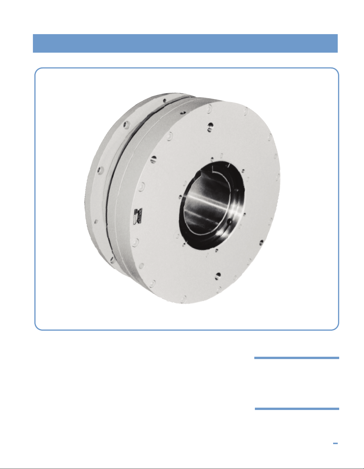
MODEL HBA
Air or Hydraulically Actuated Brakes
MODEL HBS
Spring-Set Air or Hydraulically Released Brakes
I N D U S T R I A L C L U T C H P R O D U C T S 74
Page 2
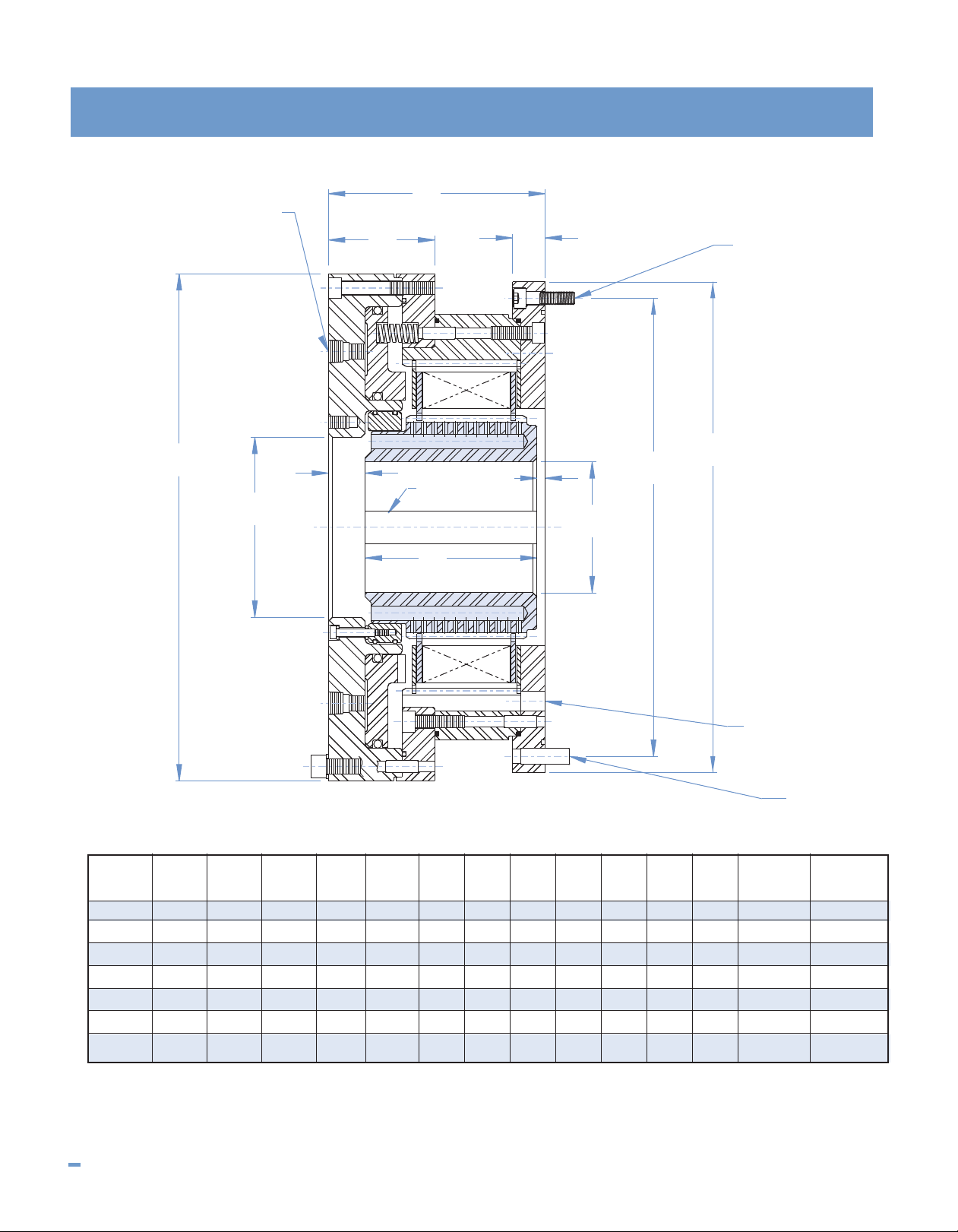
Model HBA
I
A
C
H
J
F
G
K
E
D
B
L
M
N
MAX.
K'W'Y.
OIL DRAINBACK HOLES
THRU TO SUMP
MAX.
+.002"
-.000"
+.000"
-.002"
(2) NPT ACTUATION PORTS
AT 180° ON VERT. CTR. LINE
DIMENSIONAL DATA All dimensions in inches
Brake
Model ABCDEFGHIJKL M N
HBA-8 13.25 12.875 12.000 3.000 4.000 2.63 0.84 5.88 0.75 0.19 4.94 0.75 (8) - M8 (4) - .375
HBA-10 15.50 15.000 14.000 4.000 5.500 3.25 1.00 6.63 1.13 0.25 5.25 1.00 (8) - M10 (4) - .500
HBA-13 21.25 19.750 18.750 6.000 8.750 3.50 1.13 7.31 1.19 0.13 6.00 1.50 (8) - M12 (4) - .500
HBA-15 24.50 23.500 22.000 6.500 8.750 4.13 1.38 9.31 1.25 0.25 7.81 1.50 (8) - M16 (4) - .625
HBA-16 27.50 25.500 24.000 7.500 10.000 4.25 1.38 9.44 1.38 0.25 7.81 1.50 (8) - M16 (4) - .750
HBA-18 30.25 28.750 27.000 8.000 11.000 4.69 1.75 11.84 1.56 0.50 9.78 1.50 (8) - M20 (4) - 1.00
HBA-20 32.25 31.000 29.250 9.000 12.000 5.06 1.88 12.28 1.63 0.63 10.03 1.50 (8) - M20 (4) - 1.00
NOTES: 1.) Use certified drawing dimensions only for final layouts.
2.) DXF and IGES files available upon request.
75 I N D U S T R I A L C L U T C H P R O D U C T S
3.) Dimensions subject to change without notice.
4.) All threaded fasteners are metric.
Page 3

OPERATIONAL DATA
Model HBA/HBS
rake Static Dynamic Act. Vol. Weight Weight WR
B
odel Torque (lb.-in.) Torque (lb.-in.) (in.
M
BA-8 63,000 45,000 10.6 148.6 29.5 1.43 4,000
H
HBA-10 105,000 75,000 19.2 227.7 48.2 3.48 3,400
HBA-13 280,000 200,000 37.7 411.0 106.0 15.75 2,400
HBA-15 420,000 300,000 50.0 719.0 152.0 28.68 2,150
HBA-16 595,000 425,000 66.0 900.0 197.0 45.30 1,900
HBA-18 770,000 550,000 97.0 1,385.0 308.0 84.80 1,750
BA-20 1,035,000 740,000 135.0 1,655.0 356.0 119.40 1,600
H
OTES: 1.) Operating pressure: 100 PSIG Hydraulic actuation available
N
.) Torque capacities can be modified. Consult engineering.
2
3.) Consult factory for service factors required per application.
MODEL HBA BRAKE DESCRIPTION
The Model HBA brake is an oil immersed, air or hydraulically
set brake designed to be mounted on a drive train shaft
extension. In the majority of installations, the Model HBA
brake utilizes the system’s lubricating oil for cooling.
Cooling oil is fed into the brake at the cylinder end of the unit
where it is directed into the oil distribution holes incorporated
3
)
Outer (lbs.) Inner (lbs.) (lb-ft.
.) Consult factory for oil flow requirements per application and
4
haft oil hole diameters.
s
MODEL HBS BRAKE DESCRIPTION
The Model HBS brake is identical to the Model HBA brake
except the unit is designed to be spring-set and hydraulically
or pneumatically released. This spring-set actuation feature
makes it suitable for those applications requiring the
presence of full braking torque in the event of loss of
actuation pressure or machine power.
2
nner Maximum
I
2
)
within the rotating hub for dispersal through-out the disc pack.
Unique friction plate grooving patterns, as well as the forced
oil cooling feature, allow the Model HBA brake to dissipate
the heat generated by stopping the high energy loads
common to today’s heavy duty industrial equipment.
All torque transmitting members are designed to withstand
the rigors of the loads imposed. The unit incorporates high
quality, time proven materials selected to provide strength,
durability, and reliable performance.
The Model HBA housing contains the stationary plates of the
disc pack. This housing is bolted to the stationary machine
member and provides the grounding path for stopping the
rotating components of the drive train when the disc pack is
engaged. The housing also serves as a containment for the
cooling oil and provides a path for the oil to return to the
machine reservoir.
USAGES
Any type of industrial equipment that requires braking of
high speed-high energy loads with maximum reliability
and longevity.
Those applications that must operate in adverse
environments due to the Model HBA and HBS brake’s
totally enclosed features.
Tensioning control systems.
Propeller shaft brakes, winch holding brakes, mining safety
brakes (Model HBS), conveyors, lumber and paper making
equipment are some examples of where these brakes can
be applied. They are particularly suited to mounting directly
to gear cases. This allows sharing of the lubrication and
cooling system as well as provides system compactness
and a professional design appearance.
RPM
I N D U S T R I A L C L U T C H P R O D U C T S 76
Page 4

Model HBS
+
.002"
-.000"
+.000"
-.002"
M
AX.
K'W'Y'.
M
L
D
C
B
G
J
I
K
E
A
H
F
N
OIL DRAINBACK
HOLES THRU
TO SUMP
(2) NPT
RELEASE PORTS
DIMENSIONAL DATA All dimensions in inches
Brake
Model ABCDEFGHIJKL M N
HBS-8 11.25 12.875 12.000 3.000 4.000 2.75 0.84 7.25 0.75 0.19 4.94 0.75 (8) - M8 (4) - .375
HBS-10 14.25 15.000 14.000 4.000 5.500 3.38 1.00 8.13 1.13 0.25 5.25 1.00 (8) - M10 (4) - .500
HBS-13 17.50 19.750 18.750 6.000 8.750 3.69 1.13 9.00 1.19 0.13 6.00 1.50 (8) - M12 (4) - .500
HBS-15 20.50 23.500 22.000 6.500 8.750 4.31 1.38 11.31 1.25 0.25 7.81 1.50 (8) - M16 (4) - .625
HBS-16 22.50 25.500 24.000 7.500 10.000 4.44 1.38 11.44 1.38 0.25 7.81 1.50 (8) - M16 (4) - .750
HBS-18 25.50 28.750 27.000 8.000 11.000 4.88 1.75 14.38 1.56 0.50 9.78 1.50 (8) - M20 (4) - 1.00
HBS-20 27.50 31.000 29.250 9.000 12.000 5.31 1.88 14.88 1.63 0.63 10.03 1.50 (8) - M20 (4) - 1.00
NOTES: 1.) Use certified drawing dimensions only for final layouts.
2.) DXF and IGES files available upon request.
OPERATIONAL DATA
Brake Static Dynamic Act. Vol. Weight Weight WR2Inner Maximum
Model Torque (lb.-in.) Torque (lb.-in.) (in.3) Outer (lbs.) Inner (lbs.) (lb-ft.2) RPM
HBS-8 37,000 26,500 6.8 135 29.5 1.43 4,000
HBS-10 63,000 45,000 12.3 205 48.2 3.48 3,400
HBS-13 168,000 120,000 24.1 370 106.0 15.75 2,400
HBS-15 245,000 175,000 32.0 650 152.0 28.68 2,150
HBS-16 350,000 250,000 42.2 815 197.0 45.30 1,900
HBS-18 455,000 325,000 62.0 1250 308.0 84.80 1,750
HBS-20 605,000 435,000 86.0 1495 356.0 119.40 1,600
NOTES: 1.) Release pressure: 400 PSIG
2.) Torque capacities can be modified. Consult engineering.
3.) Consult factory for service factors required per application.
3.) Dimensions subject to change without notice.
4.) All threaded fasteners are metric.
4.) Consult factory for oil flow requirements per application and shaft oil hole
diameters.
77 I N D U S T R I A L C L U T C H P R O D U C T S
 Loading...