

Page 1
Standard Vent Clutches
Grinding Mill Clutches
• Designed for heavy duty applications
• Quick, smooth starting
• High heat dissipation for jogging and inching
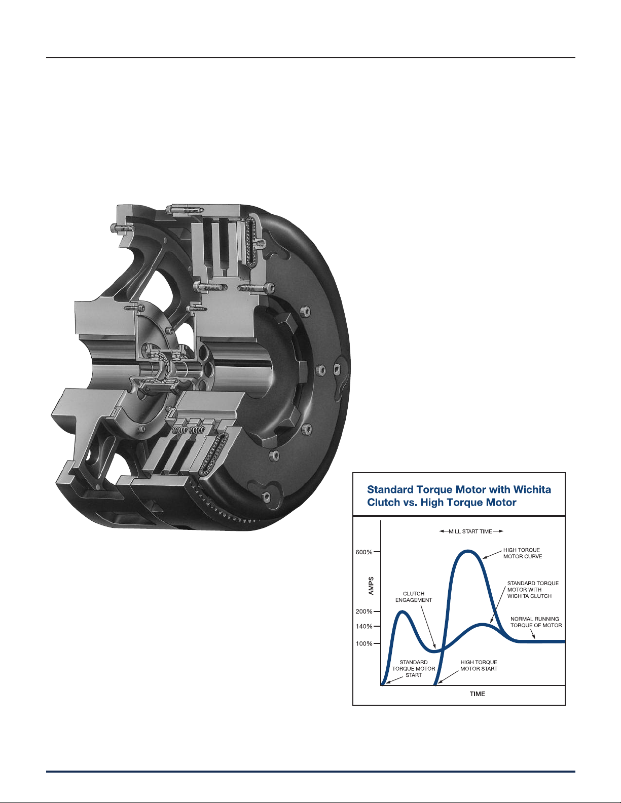
Wichita Grinding Mill Clutches are specially
designed to provide quick, smooth starts with
limited current surge for heavy duty grinding
mills. The clutch is adaptable to remote
control allowing centralized op er a tion through
simple air or electric circuits.
• No adjustment or lubrictation
• Eliminates need for special high torque
motors
• Torque capacity not affected by
centrifugal force
• High heat dis si pa tion for jogging
and inching
• New high coefficient, high energy
absorbing friction material standard for
grinding mill applications
136 Wichita Clutch 800-964-3262
P-1100-WC 1/12
Page 2

Standard Vent Clutches
Grinding Mill Clutches
Specifications
Technical
Model Total Total Driving Adapter Diameter Max. Speed (RPM) HP Lining Rated Torq.
Size Air Weight WR2 Ring & Disc Friction For 6000 FPM @ per 100 Area in.lbs.
ATD– Supply lb. lb.ft.2 Wt. WR2 Disc-in. Fric Disc O.D. RPM in.
211-X GMC 5/8"-18 130 24 57 16 11 2,100 18 228 42,294
214H-X GMC 5/8"-18 333 111 152 58 14 1,640 40 336 95,228
314H-X GMC 5/8"-18 385 132 190 75 14 1,640 60 504 142,842
318H-X GMC 1"-14 727 333 356 220 18 1,275 120 792 299,250
321-X GMC 1"-14 980 663 500 280 21 1,100 150 1,086 349,790
324H-X GMC 1"-14 1,350 970 590 600 24 950 270 1,722 613,130
327-X GMC 1"-14 1,580 1,130 675 540 27 850 300 2,190 688,275
230H-X GMC 1"-14 2,126 2,046 1,036 1,150 30 760 380 1,664 869,820
330H-X GMC 1"-14 2,600 2,100 1,125 1,250 30 760 570 2,496 1,304,730
430H-X GMC 1"-14 3,578 2,980 1,497 1,148 30 760 760 3,328 1,739,640
336H-X GMC 1"-14 3,550 4,650 1,510 2,215 36 640 885 3,450 2,134,650
342-X GMC 1-1/2"-12 4,815 10,505 2,315 6,130 42 540 1,275 4,212 2,898,070
248-X GMC 1-1/2"-12 6,580 16,275 2,825 9,523 48 475 1,600 4,020 3,730,650
348-X GMC 1-1/2"-12 7,540 18,470 3,274 9,700 48 475 2,400 6,030 5,595,975
448-X GMC 1-1/2"-12 48 475 3,200 8,040 7,461,300
260-X GMC 1-1/2"-12 10,600 37,300 5,750 23,600 60 380 3,470 7,240 7,913,500
360-X GMC 1-1/2"-12 13,390 47,850 5,900 27,550 60 380 5,200 10,850 11,870,250
460-X GMC 1-1/2"-12 16,860 57,705 7,500 33,238 60 380 6,940 14,480 15,827,000
560-X GMC 1-1/2"-12 20,050 78,642 8,300 28,512 60 380 8,675 18,100 19,783,750
372-X GMC 1-1/2"-12 72 300 7,758 14,460 18,573,450
472-X GMC 1-1/2"-12 72 300 10,344 19,280 24,764,600
572-X GMC 1-1/2"-12 72 300 12,930 24,100 30,955,750
Capacity
2
100 PSI
E
P-1100-WC • 1/11
Wichita Clutch 800-964-3262 137
Page 3
Standard Vent Clutches
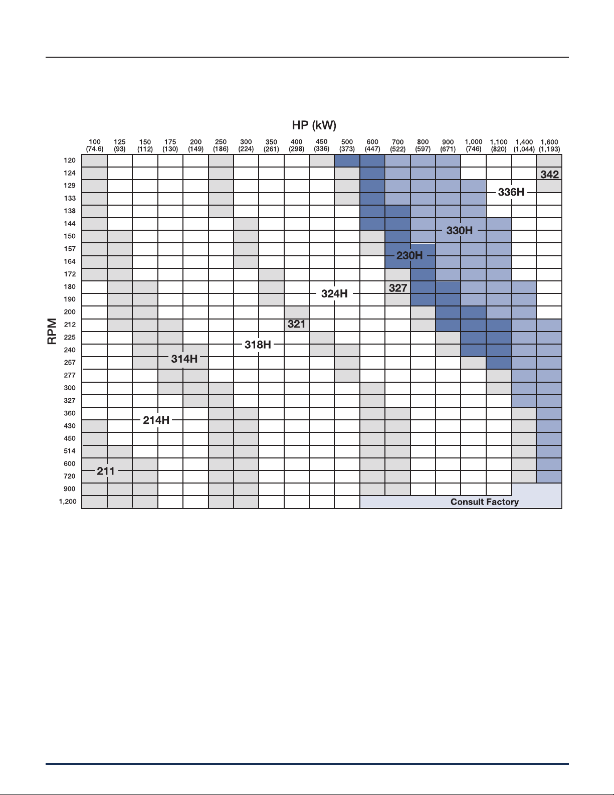
Grinding Mill Quick Selection Chart
138 Wichita Clutch 800-964-3262
P-1100-WC 1/12
Page 4

Standard Vent Clutches
Grinding Mill Quick Selection Chart
E
P-1100-WC 1/12
Wichita Clutch 800-964-3262 139
Page 5

Standard Vent Clutches
Grinding Mill Quick Selection Chart
140 Wichita Clutch 800-964-3262
P-1100-WC 1/12
Page 6

Standard Vent Clutches
Air Hose Kits
Model Part Number
8" 8-908-812-200-3
8-908-821-200-4 QRV
8-911-813-200-3 HS
11" 8-911-812-200-4
8-911-821-200-5 QRV
8-911-813-200-3 HS
14" 8-914-812-201-5
8-914-821-202-5 QRV
8-914-813-204-3 HS
Model Part Number
30"H 8-931-821-400-5 QRV
Model Part Number
18" 8-918-812-301-5
8-918-821-300-5 QRV
8-918-815-301-3 HS
21"/18H 8-921-812-301-5
8-921-821-302-5 QRV
8-921-812-300-5 HS
24" 8-924-812-300-5
8-924-821-302-5 QRV
27"/24H 8-927-812-300-5
8-927-821-301-5 QRV
8-927-812-302-5 HS
Model Part Number
60" 8-960-812-300-5
8-960-834-300-5 QRV
Model Part Number
30" 8-930-815-201-5
30"H 8-931-821-200-5 QRV
8-931-812-200-5 HS
36" 8-936-815-200-5
8-936-821-200-5 QRV
8-936-815-201-5 HS
42" 8-942-815-200-5
8-942-821-200-5 QRV
48" 8-948-815-200-5
8-948-821-200-5 QRV
Air hose kits contain all
nec es sary parts (fittings, hoses
and extensions) to com plete ly
plumb the clutch.
Optional Quick Release Valves
can replace elbows on most
units (see page 144).
Roto-couplings
(see page 144).
E
P-1100-WC 1/12
1 Spud Hose Kits
Model Part Number
18" 8-918-815-101-3 HS
21" 8-921-815-101-3 HS
Wichita Clutch 800-964-3262 141
Page 7

Standard Vent Clutches
Grinding Mill Clutches
Driving Adapters
The driving adapter is
de signed to allow the clutch
to be used in a shaft-toshaft or through-shaft
coupling ar range ment. The
quick-change feature, using
a driving elbow piece be tween the driving adapter
and the clutch driving ring,
enables replacement of any
wearing clutch part without
dis turb ing either shaft.
(See Notes 1 & 2)
Without axial
locking device
Dimensions: inches (Consult factory for drawing before final layout.)
Model C* C1* F*
Size
ATD– B
211 GMC 3.00 3.00 — 5.00 2.00 3.00 4.25 11.94 10.00 —
214H GMC 3.25 4.13 — 6.25 2.13 3.38 5.75 16.31 11.88 —
314H GMC 3.25 4.13 — 6.25 2.13 3.38 7.18 16.31 13.38 —
318H GMC 6.00 4.00 — 6.00 4.38 4.00 7.31 21.31 17.43 —
321 GMC 6.00 6.50 — 9.00 4.00 5.38 8.63 21.31 20.50 —
324H GMC 7.31 7.50 — 10.00 5.56 5.38 8.43 27.00 21.56 —
327 GMC 7.31 7.63 — 11.50 5.56 7.00 9.00 27.00 20.94 —
230H GMC 8.75 9.38 9.38 14.00 6.50 7.00 7.88 32.38 22.63 24.43
330H GMC 8.75 9.38 9.38 14.00 6.50 7.00 10.88 32.38 25.25 26.94
336H GMC 10.00 9.38 9.38 14.00 7.88 8.00 12.88 38.25 26.75 34.75
342 GMC 10.00 12.00 12.00 18.00 7.43 10.00 11.88 44.13 27.63 34.50
248 GMC 13.63 15.00 13.25 20.00 10.13 12.00 10.88 52.38 29.63 36.88
348 GMC 13.63 15.00 13.25 20.00 10.13 12.00 13.63 52.38 32.13 39.50
260 GMC 16.25 18.00 15.00 24.00 12.25 14.00 16.25 61.50 40.00 42.50
360 GMC 16.25 18.00 15.00 24.00 12.25 14.00 20.00 61.50 43.75 46.25
460 GMC 16.25 18.00 15.00 24.00 12.25 14.00 23.50 61.50 47.13 49.63
560 GMC 20.25 17.00 17.00 30.00 16.25 17.00 27.00 61.50 — 57.20
* Maximum bore uses rectangular key, contact Wichita Engineering.
Note: For mounting, use socket head capscrews conforming to the ASTM-574-97a.
Max. Bore Max. Bore
Rect. Key
Rect. Key
D E
Max. Bore
Rect. Key
G J L L
1
142 Wichita Clutch 800-964-3262
P-1100-WC 1/12
Page 8

With axial
locking device
The axial locking device is
an optional feature offered
by Wichita. This device
prevents dam age to the
mill motor bear ings during
motor start-up by axially
locking the armature
to magnetic center.
Standard Vent Clutches
Grinding Mill Clutches
(See Notes 1 & 2)
(See Note 3)
Notes:
1. Air Hose Kits, page 141.
2. Quick Release Valves, page 144.
3. Roto-couplings, page 144.
Model
Size
ATD– N R S S1 S2
211 GMC 2.25 13.63 N/A — 5.38 1/2" NPT 2 1.62 — 1/2" NPT 5/8”-18
214H GMC 2.25 17.50 3.25 — 3.13 1/2" NPT 2 2.13 — 1/2" NPT 5/8”-18
314H GMC 2.25 17.50 4.75 — 3.13 1/2" NPT 2 2.13 — 1/2" NPT 5/8”-18
318H GMC 2.43 22.00 5.88 — 3.50 1/2" NPT 3 3.06 — 1/2" NPT 1”-14
321 GMC 2.38 25.00 6.25 — 6.25 1/2" NPT 3 4.75 — 1/2" NPT 1”-14
324H GMC 2.75 28.00 6.25 — 5.50 1/2" NPT 3 4.50 — 1/2" NPT 1”-14
327 GMC 2.38 31.00 6.50 — 4.63 1/2" NPT 3 3.75 — 1/2" NPT 1”-14
230H GMC 2.75 34.00 5.63 5.75 5.75 1/2" NPT 4 4.25 5.00 1/2" NPT 1”-14
330H GMC 2.88 34.00 8.13 7.43 5.75 1/2" NPT 4 4.25 5.00 1/2" NPT 1”-14
336H GMC 2.88 41.00 9.13 12.13 4.00 1/2" NPT 4 2.50 10.00 1/2" NPT 1”-14
342 GMC 3.50 49.25 9.63 12.69 5.69 1/2" NPT 4 3.50 10.00 1/2" NPT 1-1/2”-12
248 GMC 3.75 56.00 7.38 13.25 6.13 1/2" NPT 4 2.75 10.00 1/2" NPT 1-1/2”-12
348 GMC 3.50 56.00 9.88 13.38 6.13 1/2" NPT 4 2.75 10.00 1/2" NPT 1-1/2”-12
260 GMC 2.00 66.75 9.00 14.00 11.50 1/2" NPT 6 7.50 10.00 1/2" NPT 1-1/2”-12
360 GMC 2.00 66.75 13.00 14.00 11.50 1/2" NPT 6 7.50 10.00 1/2" NPT 1-1/2”-12
460 GMC 2.00 66.75 16.50 14.00 11.50 1/2" NPT 6 7.50 10.00 1/2" NPT 1-1/2”-12
560 GMC 4.0 74.25 20.13 14.60 — 1/2" NPT 6 — 10.00 1/2" NPT 1-1/2”-12
U V
tap size
spuds
X Y
tap size Supply
Z Air
E
P-1100-WC 1/12
Wichita Clutch 800-964-3262 143
Page 9

Standard Vent Clutches
1/2" NPT (for Optional Mufer 4-263-605-002-0)
Grinding Mill Clutches
Quick Release Valve
8-263-610-011-1 7/8" – 14 Thread
8-263-610-021-1 1/2" NPT
The Wichita Springless Quick Release Valve
discharges twice as fast as any other valve
tested in our laboratory and is four to five times
faster than some common makes of valves.
This valve will close and seal with less than 20
lbs. pressure. Most others require 25 to 30 lbs.
to definitely seal. In actual tests, the Wichita
Valve made many hundreds of thousands of
engagements and dis en gage ments before the
slightest leak occurred, or any parts needed
re place ment. Other valves which were tested
required major re place ment in fewer than 20,000
cycles.
Quality Material
Body and Cap: High strength aluminum alloy
Stem: Molded nylon
Check Valve: Nylon ball
"O" Ring: Neoprene
Standard thread arrangement of 1/2" size.
1/2" pipe thread on the tube connection
and choice of 1/2" pipe thread, or stan dard
7/8-14NF thread for flared fitting thread on
inlet connection. (Fits standard No. 10
high-pressure hose fitting.)
Roto-Couplings
• Long life, no maintenance
• Felt seal eliminates bearing con tam i na tion
• Fast, easy installation
The Wichita Roto-coupling is a device to
connect, or couple, a non-rotating air, gas, or
fluid line to a rotating shaft.
Dimensions: inches
Wichita Part No. AA B C D E F G H Max. RPM
8-240-701-003-1 5/8-18NF 1/4" NPT .40 1.046 2.250 1.500 2.13 3.297 3,500
8-240-705-001-1 1"-14 NF 1/2" NPT .75 1.250 3.188 2.500 3.00 4.438 3,500
8-240-708-001-1 1"-14 NF 3/4" NPT .75 1.313 4.688 2.875 3.69 5.440 3,500
8-240-710-002-1 1-1/2"-12 NF 1" NPT 1.13 1.937 4.875 3.250 3.44 6.812 2,500
8-240-712-001-1 2"-12 NF 1-1/2" NPT 1.13 2.813 5.250 4.250 5.38 8.062 2,500
8-240-714-001-3 2" NPT 2" NPT 1.50 3.000 7.062 4.625 7.00 10.062 1,000
8-240-716-000-3 2-1/2" NPT 2-1/2" NPT 1.88 3.250 9.375 7.000 7.75 12.625 750
144 Wichita Clutch 800-964-3262
P-1100-WC 1/12
 Loading...