

Page 1
Industrial Clutch Products
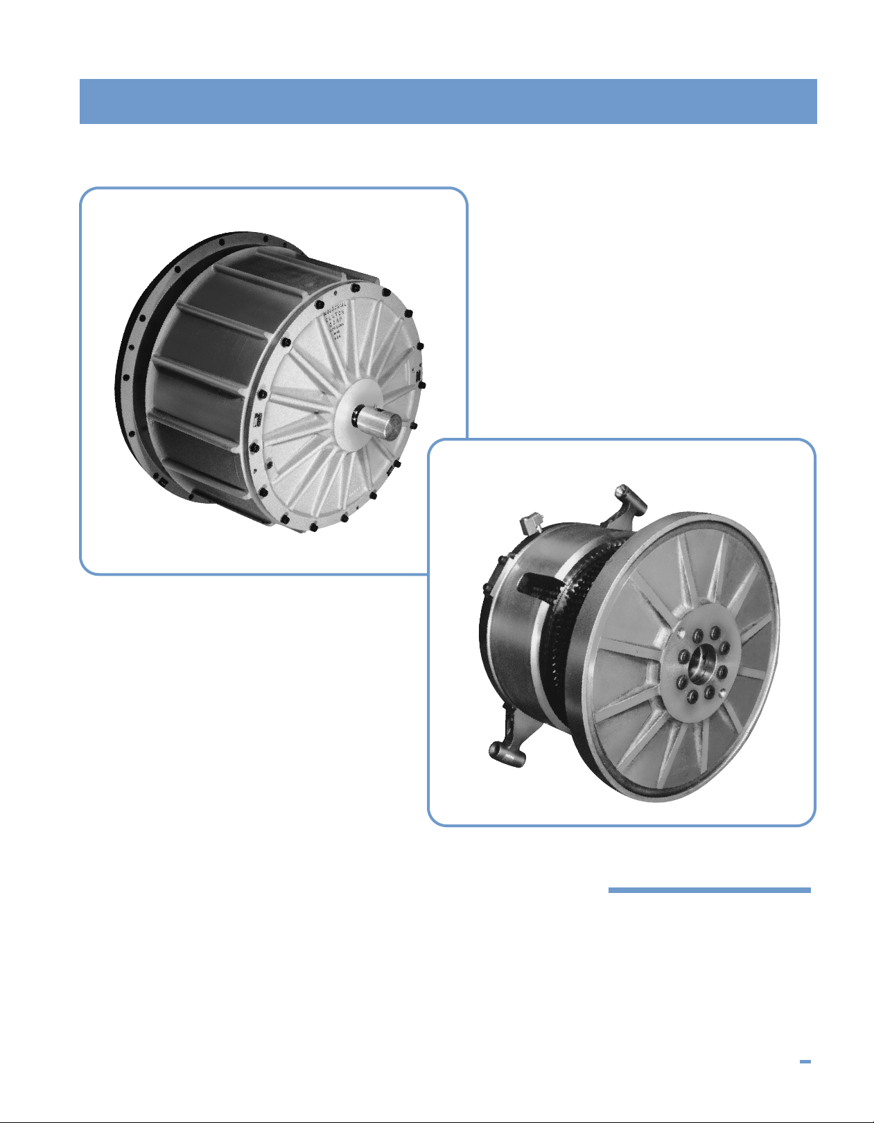
MODEL CBA
Air or Hydraulically
Actuated Combination
Clutch-Brakes
I N D U S T R I A L C L U T C H P R O D U C T S 62
Page 2

MODEL CBA
Air or Hydraulically Actuated Combination Clutch-Brakes
Performance Characteristics
The Model CBA combination clutch-brake is an oil immersed
unit utilizing a self-contained cooling oil-pumping system and
capable of being actuated with either air or hydraulic
pressure.
These units are capable of running at higher speeds and
greater cyclic frequencies without exhibiting the wear
magnitudes common to clutches and brakes operating dry
under the same conditions.
Reliability and longevity are the most important features
these units have to offer and find usage in those
applications requiring the ultimate in clutch and brake
performance.
Over fifteen years of field experience shows intervals
between maintenance and machine up-time to increase from
five to ten times when oil immersed units are used as direct
replacements for those operating dry.
Industrial Clutch Products has designed the Model CBA unit
to be compatible and complementary to their dry unit
products. All of the desirable features found in our standard
line of dry products were carefully evaluated for
incorporation into the Model CBA combination clutch-brake.
The user may expect the lowest possible driven inertia;
fastest speed of response; and the same high quality
ruggedness contained throughout our product line.
The Model CBA unit was designed and developed as part of
our commitment to provide wide ranging and usefully
products for the heavy industrial marketplace. As a result,
the user has another level of performance from which to
choose.
Advantages
Combination clutch-brake eliminates the
possibility of clutch-brake fight
Increase in lining life
Increase in reliabillity
Impervious to adverse operating
environments
Low driven inertia
Fast speed of response
High cyclic rates
High operating speeds
Usages
Original Equipment
Machinery which requires unusually high performance
levels, operating speeds, or cyclic rates as well as precise
stopping accuracy.
Conversions
Machinery which is being upgraded to increase production
rates, reliability, or capacity.
63 I N D U S T R I A L C L U T C H P R O D U C T S
Page 3
Model CBA Combination
Clutch-Brake Description
Model CBA
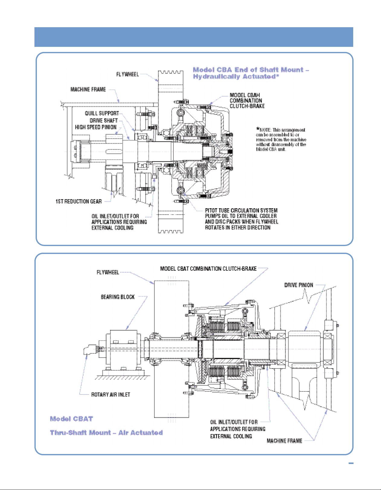
The Model CBA combination clutch-brake is arranged so
that it may be mounted in and end of shaft or thru shaft
configuration. The clutch driving members attach to the
flywheel or input power source. The stationary brake
members are attached to the machine frame by the use of a
quill member which also provides a path for moving the
cooling oil into and out of the unit if the application requires
external cooling. Refer to Figure 1 and Figure 2 for a typical
arrangement of an outboard (CBA) and thru-shaft (CBAT)
mount respectively.
The unit may be provided with either pneumatic or hydraulic
actuation chambers as well as a variety of brake springs to
accommodate the clutch and brake torque requirements.
Due to the many types of machinery configurations, it is
often more convenient to house the clutch-brake unit within
a user provided mounting cavity.
Model CBA
The Model CBA contains its own circulating oil-pumping
system which pumps oil through the disc packs from either
direction of rotation anytime the input member rotates. Refer
to Figure 3. If external cooling is required due to the speed
and cyclic rate, the internal pump output is directed from the
outer housing cavity through the quill/brake support member
and external cooler where the engagement heat is removed.
Cooled oil then returns through the quill/brake support
member into the disk pack where engagement heat is
transferred to the oil. This heated oil is then pumped back to
the cooler for heat removal.
If external cooling is not required, the circulating pump
simply moves the oil internally from the outer housing cavity
through the disk packs and back to the housing cavity where
the engagement heat is transferred through the rotating
housing into the surrounding atmosphere.
The ability of the CBA combination clutch-brake to
continuously and effectively transfer large quantities of
energy in this manner is the key factor to its longevity and
reliabililty. In addition, the torque transmitting members,
being lubricated by this same oil, are well suited to carry the
heavy duty industrial type loads these models encounter.
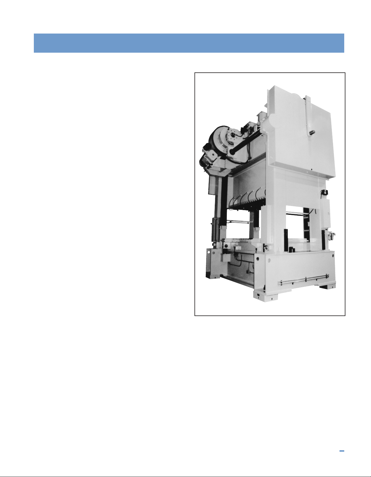
Model CBAT-32580 Combination Clutch-Brake
installed on a PTC 600-ton 144 x 60 transfer press.
Photo courtesy of Press Technology Corp.
I N D U S T R I A L C L U T C H P R O D U C T S 64
Page 4
Model CBA
D
A
G
I
H
B
F
J
E
C
DIA.
P
ILOT
O
IL OUTLET TO QUILL
FOR EXTERNAL COOLER OPTION
ACTUATION
INLET
SEE
NOTE 1
SEE
NOTE 2
SEE
N
OTE 1
S
EE
NOTE 1
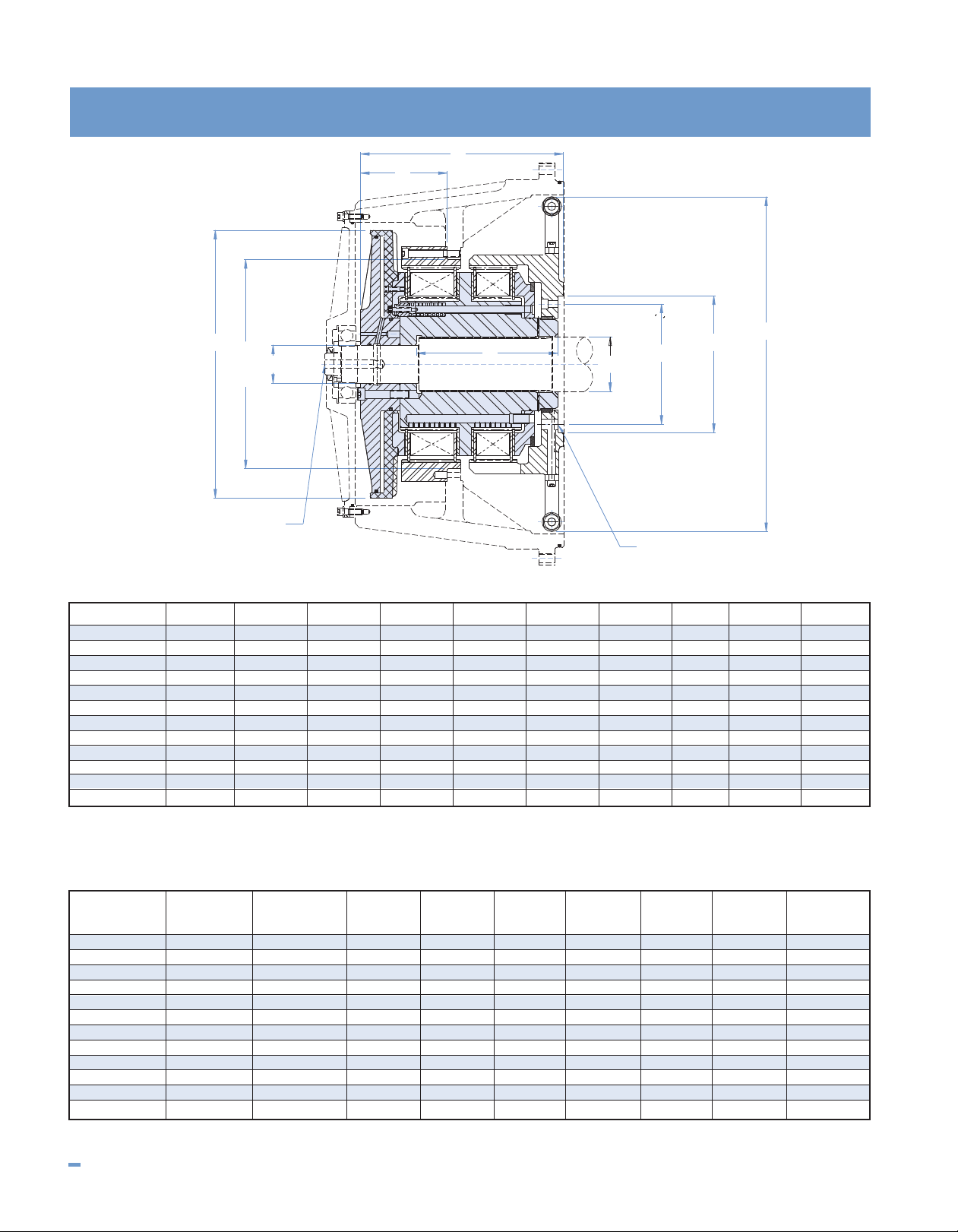
DIMENSIONAL DATA All dimensions in inches
CBA Model ABCDEFGHI J
CBA-3008 16.88 5.906 5.250 3.625 2.000 11.50 13.75 3.83 9.58 5.68
CBA-4512 16.88 5.906 5.250 3.625 2.000 11.50 13.75 5.21 10.96 7.00
CBA-6015 16.88 5.906 5.250 3.625 2.000 11.50 13.75 6.58 12.33 8.31
CBA-10025 21.63 8.661 7.625 5.000 3.000 15.250 18.25 5.51 12.90 7.65
CBA-14035 21.63 8.661 7.625 5.000 3.000 15.250 18.25 6.20 14.31 9.06
CBA-18045 21.63 8.661 7.625 5.000 3.000 15.250 18.25 6.90 15.72 10.47
CBA-24060 30.63 13.750 12.250 7.000 3.500 19.125 24.50 5.45 14.82 9.37
CBA-32580 30.63 13.750 12.250 7.000 3.500 19.125 24.50 6.06 16.69 11.24
CBA-400100 30.63 13.750 12.250 7.000 3.500 19.125 24.50 7.94 18.56 12.86
CBA-550150 34.13 13.500 12.000 9.250 5.625 34.750 30.50 8.87 22.88 16.01
CBA-650175 34.13 13.500 12.000 9.250 5.625 34.750 30.50 8.87 25.48 18.61
CBA-800200 34.13 13.500 12.000 9.250 5.625 34.750 30.50 8.87 28.08 21.21
NOTES: 1.) Industrial Clutch Prod. will supply shaft end detail and quill support drilling
NOTES: 2.) End of shaft only. For thru-shaft designs, consult engineering.
and machining details. Dimensions may be modified to suit customer requirements.
3.) Use certified drawing dimensions only for final layouts.
4.) DXF and IGES files available upon request.
5.) Dimensions subject to change without notice.
OPERATIONAL DATA
CBA Clutch Torque Brake Torque Volume Outer Inner Stationary Outer Inner Speed
Model (lb.-in.) (lb.-in.) (In.3) (lbs.) (lbs.) (lbs.) (lb.-ft.2) (lb.-ft.2) (RPM)
CBA-3008 30,000 8,000 24 30 103 43 6.5 9.5 1,200
CBA-4512 45,000 12,000 29 41 118 46 8.3 10.6 1,200
CBA-6015 60,000 15,000 33 48 132 52 9.5 11.6 1,200
CBA-10025 100,000 25,000 100 56 253 137 21 44 1,000
CBA-14035 140,000 35,000 100 70 288 151 26 49 1,000
CBA-18045 180,000 45,000 100 101 322 166 39 54 1,000
CBA-24060 240,000 60,000 175 101 635 248 55 204 800
CBA-32580 325,000 80,000 175 148 699 272 83 219 800
CBA-400100 400,000 100,000 175 212 763 296 123 235 800
CBA-550150 550,000 150,000 415 494 978 445 648 495 800
CBA-650175 650,000 175,000 444 549 1093 500 688 537 800
CBA-800200 800,000 200,000 473 604 1208 555 728 697 800
NOTES: 1.) Operating pressure: 80 PSIG air.
2.) Torque capacities can be modified. Higher torques may be obtained using hydraulic actuation. Consult engineering.
Static Dynamic Actuation Weight Weight Weight WR
2
WR
2
Maximum
65 I N D U S T R I A L C L U T C H P R O D U C T S
Page 5
Model CBA
Figure 1
Figure 2
I N D U S T R I A L C L U T C H P R O D U C T S 66
Page 6
Model CBA
MODEL CBA COMBINATION CLUTCH-BRAKE
COOLER
TEMP.
SWITCH
PRES.
SWITCH
OIL ANNULUS
HEATED OIL
FROM CLUTCH-BRAKE
F
ILTER
COOLED OIL
TO CLUTCH-BRAKE
B
RAKE/QUILL
SUPPORT MEMBER
PITOT TUBE CIRCULATION SYSTEM PUMPS OIL
TO EXTERNAL COOLER AND DISC PACKS WHEN
FLYWHEEL ROTATES IN EITHER DIRECTION
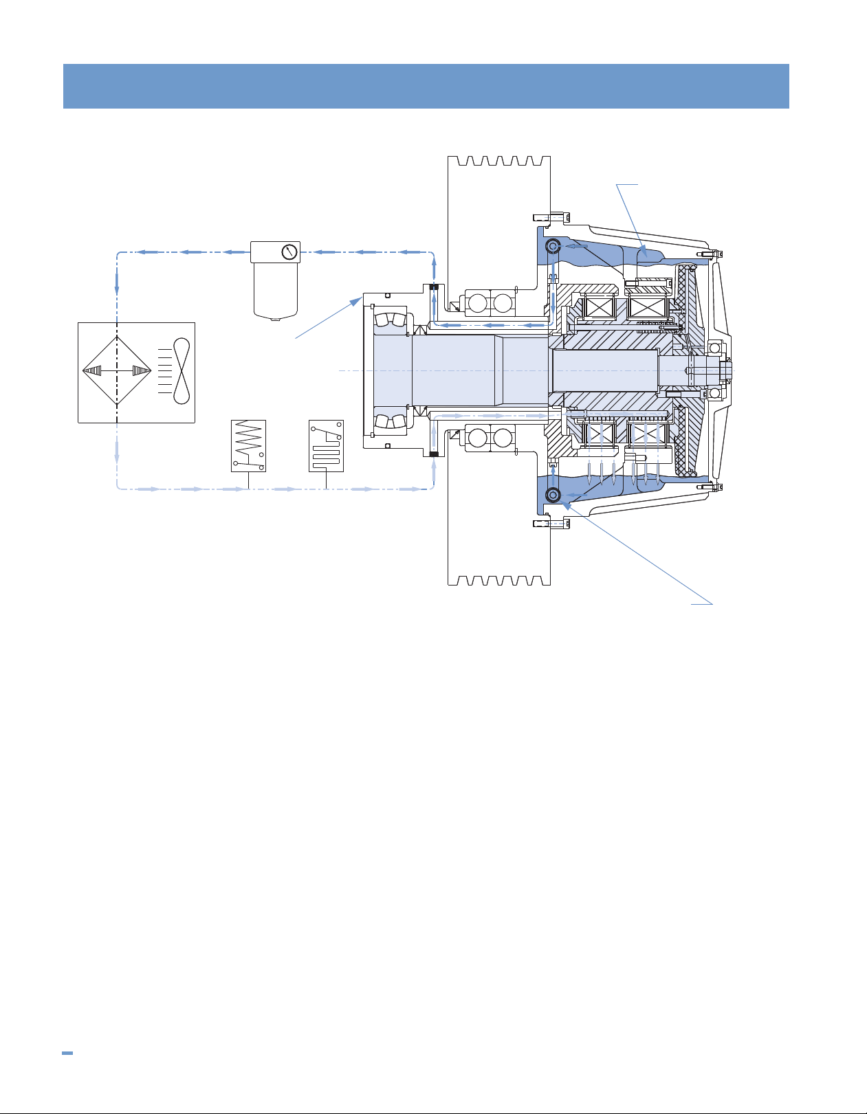
Figure 3
EXTERNAL COOLING DESCRIPTION
For those applications requiring external cooling, the pitot
tubes scoop the oil from the rotating column of oil within the
Model CBA’s housing. This oil contains the engagement
heat. The oil is then pumped through passages drilled in the
quill support member to an external cooler where the
engagement heat is removed.
Cooled oil returns through a different set of passages drilled
in the quill support member and is introduced through a
series of orifices directly into the center of the clutch and
brake disc packs. This oil provides the cooling for the disc
packs and removes the heat of engagement. It then returns
to the rotating column of oil where it is again removed by the
pitot tube pumping system and delivered to the cooler to
repeat the cycle.
The pitot tube pumping system is bi-directional and will
pump oil from either direction of rotation. Being a centrifugal
type pumping system, its output is related to the speed of
rotation. This closely matches the cooling oil requirements of
the disc packs since engagement energy is also related to
the speed of rotation in the same manner.
This system is completely self-contained and requires no
additional energy source other than housing rotation. If the
housing rotates, oil is delivered in the correct quantity to the
disc packs.
Low pressure switches,(indicating low oil level), as well as
hi-temperature switches, and a filter are normally included
as shown to complete the cooling lube system.
67 I N D U S T R I A L C L U T C H P R O D U C T S
 Loading...