

Wi2wi W2SW0025 User Manual
User Manual
Revision 0.2
January 29, 2016

Disclaimers
Wi2Wi, Inc. PRODUCTS ARE NOT AUTHORISED FOR USE AS CRITICAL COMPONENTS IN
LIFE SUPPORT DEVICES OR SYSTEMS WITHOUT THE EXPRESS WRITTEN APPROVAL OF
THE MANAGING DIRECTOR OF Wi2Wi, Inc.
The definitions used herein are:
a) Life support devices or systems are devices which (1) are intended for surgical implant into the body,
or (2) support or sustain life and whose failure to perform when properly used in accordance with the
instructions for use provided in the labeling can reasonably be expected to result in a significant injury
to the user. b) A critical component is any component of a life support device or system whose failure to
perform can be reasonably expected to cause the failure of the life support device or system, or to affect
its safety or effectiveness.
Wi2Wi does not assume responsibility for use of any of the circuitry described, no circuit patent licenses
are implied and Wi2Wi reserves the right at any time to change without notice said circuitry and
specifications.
The content of this document is to be treated as strictly confidential and is not to be disclosed,
Reproduced or used, except as authorized in writing by Wi2Wi, Inc.
IC RSS Statement:
English:
This device complies with Industry Canada license‐exempt RSS standard(s). Operation is subject to the
following two conditions:
1) This device may not cause harmful interference;
2) This device must accept any interference received, including interference that may cause
undesired operation of the device.
French:
Cet appareil est conforme à Industrie Canada une licence standard RSS exonérés (s). Son
fonctionnement est soumis aux deux conditions suivantes:
1) Cet appareil ne doit pas provoquer d'interférences
2) Cet appareil doit accepter toute interférence reçue, y compris les interférences pouvant
provoquer un fonctionnement indésirable de l'appareil.
FCC Part 15 Statement:
This device complies with part 15 of the FCC Rules. Operation is subject to the following two
conditions:
1) This device may not cause harmful interference, and
2) This device must accept any interference received, including interference that may cause
undesired operation.
This equipment has been tested and found to comply with the limits for a Class B digital device,
pursuant to part 15 of the FCC Rules. These limits are designed to provide reasonable protection against
Page 2 of 20
Copyright © 2016 Wi2Wi, Inc.

harmful interference in a residential installation. This equipment generates, uses, and radiates radio
frequency energy; and if not installed and used in accordance with the instructions, may cause harmful
interference to radio communications. However, there is no guarantee that interference will not occur in
a particular installation. If this equipment does cause harmful interference to radio or television
reception, which can be determined by turning the equipment off and on, the user is encouraged to try to
correct the interference by one or more of the following measures:
a) Reorient or relocate the receiving antenna.
b) Increase the separation between the equipment and receiver.
c) Connect the equipment into an outlet on a circuit different from that to which the receiver is
connected.
d) Consult the dealer or an experienced radio/TV technician for help.
The FCC requires the user to be notified that any changes or modifications made to this device that are
not expressly approved by Wi2Wi may void the user‟s authority to operate the equipment.
Integrator Guidance:
Only the antenna(s) described in the filings under this FCC ID or equivalent antenna(s) with
equal or lesser gain may be used with this transmitter. Any new antenna type, or higher gain
antenna would require a Class II permissive change.
If the operation of the equipment is for portable use (within 20 cm of user), or where co-location
configuration use is required; the end product, including the transmitter will require re-evaluation
in accordance to the FCC rules.
Labeling:
The final end product must be labeled in a visible area with the following:
"Contains FCC ID: XXXXXXXX, IC: YYYYYYYYY"
where XXXXXXXX, YYYYYYYYY are the approved FCC/IC ID for the device being installed.
The grantee's FCC/IC ID can be used only when all FCC/IC compliance requirements are met.
Page 3 of 20
Copyright © 2016 Wi2Wi, Inc.

Table of Contents
Disclaimers..................................................................................................................................................2
Table of Contents .......................................................................................................................................4
1. Introduction ........................................................................................................................................6
1.1 W2SW0025 Module ................................................................................................................. 6
1.2 W2SW0025 EVK Board ........................................................................................................... 6
2. Scope ....................................................................................................................................................7
2.1 Pre-requisites ........................................................................................................................... 7
2.2 Setup ........................................................................................................................................ 7
2.3 Release Package Contents ..................................................................................................... 7
2.4 Driver and Firmware Architecture ............................................................................................ 8
2.5 Driver Building ......................................................................................................................... 8
2.5.1 Kernel Configuration .......................................................................................................................... 8
2.5.2 Compile Time Driver Configuration .................................................................................................... 9
2.5.3 Building ............................................................................................................................................... 9
2.6 WiFi Functional mode Driver Installation ................................................................................. 9
2.7 MFG mode Driver Installation ................................................................................................ 10
3. WiFi Usage Examples .......................................................................................................................11
3.1 WiFi Station Mode ................................................................................................................. 11
3.2 WiFi Access Point Mode ........................................................................................................ 11
3.3 WiFi Direct Mode ................................................................................................................... 12
3.4 Data Transfer ......................................................................................................................... 12
3.5 Driver Proc and Debug commands ....................................................................................... 12
3.6 Driver Configuration commands ............................................................................................ 12
4. Configuration of Kernels .................................................................................................................13
4.1 SDIO Stack Options ............................................................................................................... 13
4.2 Kernel Compilation ................................................................................................................ 13
5. Driver building for Embedded Platforms ......................................................................................14
5.1 Driver Building for i.MX6 SoloLite EVK .................................................................................. 14
5.1.1 Requirements ................................................................................................................................... 14
5.1.2 Hardware Setup ............................................................................................................................... 14
5.1.3 Cross Compiling the Driver for i.MX6 SoloLite EVK ........................................................................ 15
5.2 Driver Building for i.MX6 WandBoard .................................................................................... 15
5.2.1 Requirements ................................................................................................................................... 15
5.2.2 Host PC for Wandboard ................................................................................................................... 15
6. References ..........................................................................................................................................20
6.1 Specifications ......................................................................................................................... 20
6.2 Trademarks, Patents and Licenses ....................................................................................... 20
6.3 Other ...................................................................................................................................... 20
Copyright © 2016 Wi2Wi, Inc.
Page 4 of 20
Revision
Revision Date
Originator
Changes
0.1 0.2
List of Figures
No table of figures entries found.
List of Tables:
No table of figures entries found.
Revision History:
Copyright © 2016 Wi2Wi, Inc.
Page 5 of 20
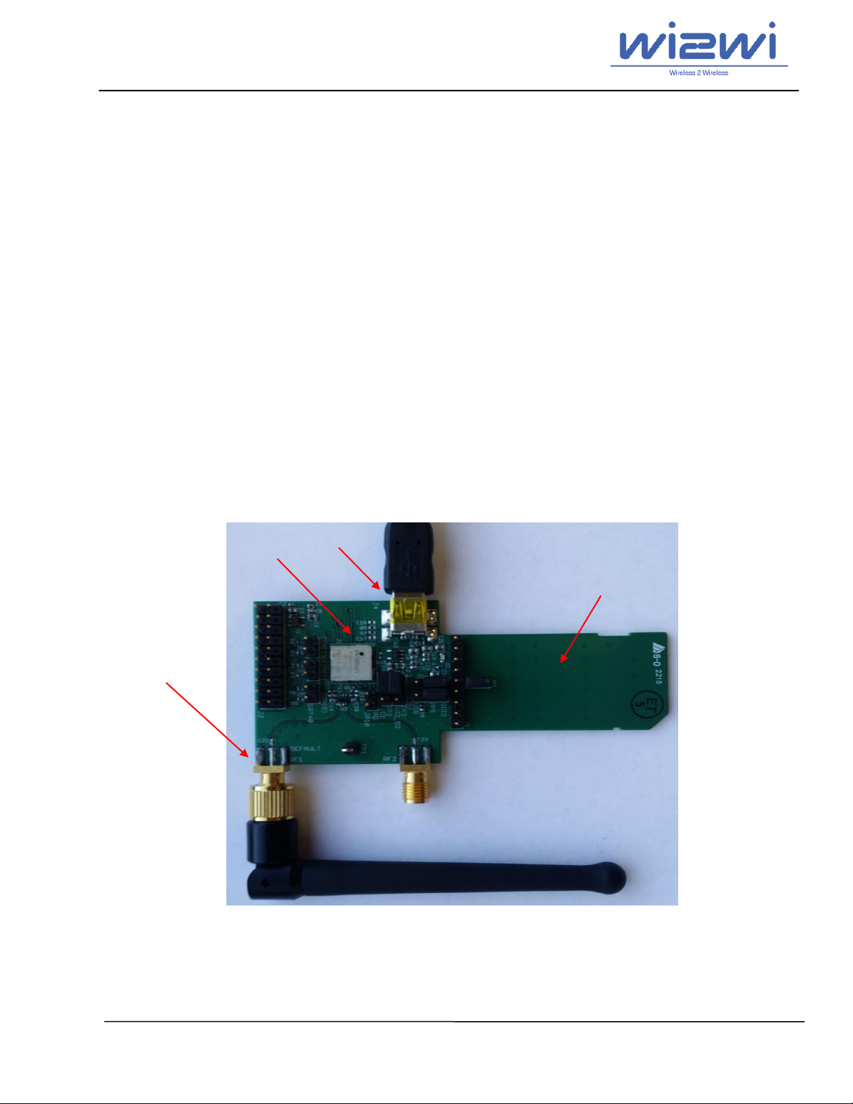
W2SW0025 Module
Default SMA Connector
Mini USB Connector
SDIO Connector
1. Introduction
This document describes how to set up the W2SW0025 EVK to evaluate Wi-Fi performance of the
W2SW0025 host based module. It also describes how to compile the Linux reference drivers and
provides some basic usage example.
1.1 W2SW0025 Module
W2SW0025 is a complete wireless subsystem featuring 802.11 b/g/n WLAN capabilities in a small form
factor module. The W2SW0025 module is designed to simplify the process of adding wireless capability
without lengthy design cycles or complex RF circuit. It is completely tested for functionality and
performance along with coexistence with other wireless standards.
W2SW0025 has been fully optimized for throughput and receive sensitivity using careful design
practices Based on world-class silicon from Marvell.
1.2 W2SW0025 EVK Board
The W2SW0025 EVK board is a development platform based on the W2SW0025 with integrated USB
and SDIO. This EVB shows the abilities of the W2SW0025 and it is perfect for learning and developing
USB-based applications using the W2SW0025. The W2SW0025 evaluation kit includes an evaluation
board which can be used as a reference design for the W2SW0025 modules.
Figure 1: W2SW0025 Evaluation Kit Overview
Copyright © 2016 Wi2Wi, Inc.
Page 6 of 20
 Loading...