

WHYNTER 14,000 BTU PORTABLE AIR CONDITIONER
Model # : ARC-148MS
INSTRUCTION MANUAL
Congratulations on your new Whynter product. To ensure proper operation, please read this Instruction Manual carefully before
using this product. Keep this manual in a safe place for future reference.

Table of Contents
Safety Precautions
Safety Precautions . ...........................................................................................................................................................
Installation Instructions
Preparation............................................................................................................................................................................
Design Notice.......................................................................................................................................................................
Ambient Temperature Range For Unit Operating..................................................................................................
Exhaust Hose Installation.................................................................................................................................................
Choosing The Right Location..........................................................................................................................................
Energy Rating Information .............................................................................................................................................
Tools Needed........................................................................................................................................................................
Accessories.............................................................................................................................................................................
Window Installation Kit.....................................................................................................................................................
Installation..............................................................................................................................................................................
Operating Instructions
Control Panel Features......................................................................................................................................................
Operation Instructions......................................................................................................................................................
Other features......................................................................................................................................................................
03
10
10
11
11
11
11
13
13
13
16
14
18
19
Maintenance
Safety Precautions..............................................................................................................................................................
Air Filter Cleaning ..............................................................................................................................................................
Unit Cleaning ......................................................................................................................................................................
Store the unit when not in use .....................................................................................................................................
Troubleshooting Tips
Troubleshooting Tips ................................................................................................................................................
22
21
21
21
21
- 23
Safety
Safety Precautions
Read Safety Precautions Before Operation and Installation
To prevent death or injury to the user or other people and property damage, the
following instructions must be followed. Incorrect operation due to ignoring of
instructions may cause death, harm or damage.
Safety
Precautions
WARNING
This symbol indicates the possibility of
personnel injury or loss of life.
This symbol indicates the possibility of
property damage or serious consequences.
CAUTION
WARNING
Installation must be performed according to the installation instructions. Improper installation
•
can cause water leakage, electrical shock, or fire.
Use only the included accessories and parts, and specified tools for the installation. Using non-
•
standard parts can cause water leakage, electrical shock, fire, and injury or property damage.
Make sure that the outlet you are using is grounded and has the appropriate voltage.
•
The power cord is equipped with a three-prong grounding plug to protect against shock.
Voltage information can be found on the nameplate of the unit.
Your unit must be used in a properly grounded wall receptacle. If the wall receptacle you
•
intend to use is not adequately grounded or protected by a time delay fuse or circuit breaker
(the fuse or circuit breaker needed is determined by the maximum current of the unit. The
maximum current is indicated on the nameplate located on unit), have a qualified electrician
install the proper receptacle.
Install the unit on a flat, sturdy surface. Failure to do so could result in damage or excessive
•
noise and vibration.
The unit must be kept free from obstruction to ensure proper function and to mitigate safety
•
hazards.
Do not modify the length of the power cord or use an extension cord to power the unit.
•
Do not share a single outlet with other electrical appliances. Improper power supply can
•
cause fire or electrical shock.
•
Do not install your air conditioner in a wet room such as a bathroom or laundry room. Too
much exposure to water can cause electrical components to short circuit.
Do not install the unit in a location that may be exposed to combustible gas, as this could
•
cause fire.
The unit has wheels to facilitate moving. Make sure not to use the wheels on thick carpet or to
roll over objects, as these could cause tipping.
Do not operate a unit that it has been dropped or damaged.
•
The appliance with electric heater shall have at least 3 feet of space to the combustible
•
materials.
Do not touch the unit with wet or damp hands or when barefoot.
•
If the air conditioner is knocked over during use, turn off the unit and unplug it from the main
•
power supply immediately. Visually inspect the unit to ensure there is no damage. If you
suspect the unit has been damaged, contact a technician or customer service for assistance.
Page 3

Safety
Precautions
•
•
•
•
•
•
•
•
•
•
•
•
•
•
•
•
•
•
•
•
•
•
In a thunderstorm, the power must be cut off to avoid damage to the machine due to lightning.
Your air conditioner should be used in such a way that it is protected from moisture.
e.g. condensation, splashed water, etc. Do not place or store your air conditioner where it can
fall or be pulled into water or any other liquid. Unplug immediately if it occurs.
All wiring must be performed strictly in accordance with the wiring diagram located inside of
the unit.
The unit's circuit board(PCB) is designed with a fuse to provide overcurrent protection. The
specifications of the fuse are printed on the circuit board, such as: T 3.15A/250V, etc.
When the water drainage function is not in use, keep the upper and the lower drain plug firmly
plugged into to the unit to prevent choking.
CAUTION
This appliance is not intended for use by persons (including children) with reduced physical,
sensory or mental capabilities or lack of experience and knowledge, unless they have been
given supervision or instruction concerning use of the appliance by a person responsible for
their safety. Children should be supervised to ensure that they do not play with the appliance.
Children must be supervised around the unit at all times.
If the supply cord is damaged, it must be replaced by the manufacturer, its service agent or
similarly qualified persons in order to avoid a hazard.
Prior to cleaning or other maintenance, the appliance must be disconnected from the supply mains.
Do not remove any fixed covers. Never use this appliance if it is not working properly, or if it has
been dropped or damaged.
Do not run cord under carpeting. Do not cover cord with throw rugs, runners, or similar
coverings. Do not route cord under furniture or appliances. Arrange cord away from traffic area
and where it will not be tripped over.
Do not operate unit with a damaged cord, plug, power fuse or circuit breaker. Return to an
authorized service facility for examination and/or repair.
To reduce the risk of fire or electric shock, do not use this fan with any solid-state speed control device.
The appliance shall be installed in accordance with national wiring regulations.
Contact the manufacturer or authorized service technician for repair or maintenance information of
this unit.
Contact the manufacturer or authorized installer for installation questions of this unit.
Do not cover or obstruct the inlet or outlet grilles.
Do not use this product for functions other than those described in this instruction manual.
Before cleaning, turn off the power and unplug the unit.
Disconnect the power if strange sounds, smell, or smoke comes from it and contact the
manufacturer or authorized service technician for assistance.
Do not press the buttons on the control panel with anything other than your fingers.
Do not remove any fixed covers. Contact the manufacturer or authorized service technician if this unit
if it is not working properly, or if it has been dropped or damaged.
Do not operate or stop the unit by inserting or pulling out the power cord plug.
Page 4

•
Do not use hazardous chemicals to clean or come into contact with the unit. Do not use the unit
in the presence of inflammable substances or vapour such as alcohol, insecticides, petrol,etc.
Always transport your air conditioner in a vertical position and stand on a stable, level surface
•
during use.
•
Always contact the manufacturer or authorized service technician a qualified person to carry out repairs
using parts recommended or obtained by the manufacturer.
•
Hold the plug by the head of the power plug when taking it out.
•
Turn off the product when not in use.
WARNING
Do not use means to accelerate the defrosting process or to clean, other than those recommended by
the manufacturer.
The appliance shall be stored in a room without continuously operating ignition sources (for example:
open flames, an operating gas appliance or an operating electric heater).
Do not pierce or burn.
Be aware that the refrigerants may not contain an odor.
The appliance should be installed, operated and stored in a room with a floor area according to the amount of
refrigerant to be charged. For specific information on the type of refrigerant and the amount, please refer to the
relevant label on the unit itself. When there are differences between the label and the manual on the Min.
room area description, the description on label shall prevail.
Safety
Precautions
SAFETY COMPLIANCE
Compliance with national gas regulations shall be observed.
Keep ventilation openings clear of obstruction.
The appliance shall be stored so as to prevent mechanical damage from occurring.
A warning that the appliance shall be stored in a well-ventilated area where the room size corresponds
to the room area as specified for operation.
Any person who is involved with working on or breaking into a refrigerant circuit should hold a current valid
certificate from an industry-accredited assessment authority, which authorizes their competence to handle
refrigerants safely in accordance with an industry recognized assessment specification.
Servicing shall only be performed as recommended by the equipment manufacturer. Maintenance and
repair requiring the assistance of other skilled personnel shall be carried out under the supervision of
the person competent in the use of flammable refrigerants.
P
se follow the ins
lea
any damage or hazard. Flammable Refrigerant R32 is used within air conditioner. When maintaining or
disposing the air conditioner, the refrigerant (R32) shall be recovered properly
to air directly.
No any open fire or device like switch which may generate spark/arcing shall be around air conditioner
to avoid causing ignition of the flammable refrigerant used.
Please follow the instruction carefully to store or maintain the air conditioner to prevent
mechanical damage from occurring.
Flammable refrigerant -R32 is used in air conditioner. Please follow the instruction carefully to avoid
any hazard. For specific information on the type of gas and the amount,please to the relevant label on
the unit itself.
tructio
ns carefully to handle, install, clear, and service the air conditioner to avoid
and shall not discharge
Page 5
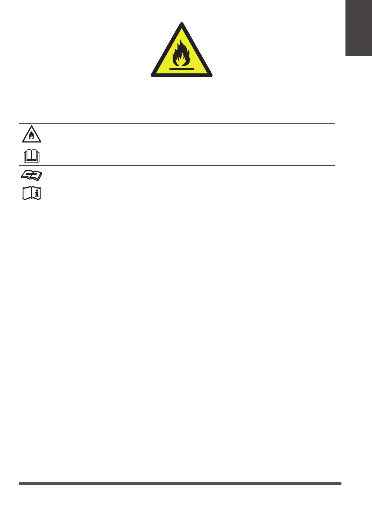
Caution: Risk of fire/flammable materials
Explanation of symbols displayed on the unit(For the unit adopts R32/R290 Refrigerant only):
Safety
WARNING
CAUTION
CAUTION
CAUTION
This symbol shows that this appliance used a flammable refrigerant. If the refrigerant
is leaked and exposed to an external ignition source, there is a risk of fire.
This symbol shows that the operation manual should be read carefully.
This symbol shows that a service personnel should be handling this equipment
with reference to the installation manual.
This symbol shows that information is available such as the operating manual or
installation manual.
1. Transport of equipment containing flammable refrigerants.
See transport regulations
2. Marking of equipment using signs.
See local regulations
3. Disposal of equipment using flammable refrigerants.
See national regulations.
4. Storage of equipment/appliances.
The storage of the equipment should be in accordance with the manufacturer's instructions.
5. Storage of packed (unsold) equipment.
Storage package protection should be constructed such that mechanical damage to the equipment
inside the package will not cause a leak of the refrigerant charge. The maximum number of pieces of
equipment permitted to be stored together will be determined by local regulations.
6. Information on servicing.
1)Checks to the area
Prior to beginning work on systems containing flammable refrigerants, safety checks are necessary
to ensure that the risk of ignition is minimized. For repair to the refrigerating system, the following
precautions shall be complied with prior to conducting work on the system.
2)Work procedure
Work shall be undertaken under a controlled procedure so as to minimize the risk of a flammable
gas or vapor being present while the work is being performed.
3)General work area
All maintenance staff and others working in the local area shall be instructed on the nature of work
being carried out. Work in confined spaces shall be avoided. The area around the workspace shall be
sectioned off. Ensure that the conditions within the area have been made safe by control of
flammable material.
4)Checking for presence of refrigerant
Page 6

Safety
Precautions
The area shall be checked with an appropriate refrigerant detector prior to and during work, to ensure
the technician is aware of potentially flammable atmospheres. Ensure that the leak detection
equipment being used is suitable for use with flammable refrigerants, i.e. non-sparking, adequately
sealed or intrinsically safe.
5)Presence of fire extinguisher
If any hot work is to be conducted on the refrigeration equipment or any associated parts, appropriate
fire extinguishing equipment shall be available to hand. Have a dry powder or CO2 fire extinguisher
adjacent to the charging area.
6)No ignition sources
No person carrying out work in relation to a refrigeration system which involves exposing any pipe
work that contains or has contained flammable refrigerant shall use any sources of ignition in such a
manner that it may lead to the risk of fire or explosion. All possible ignition sources, including cigarette
smoking, should be kept sufficiently far away from the site of installation, repairing, removing and
disposal, during which flammable refrigerant can possibly be released to the surrounding space. Prior
to work taking place, the area around the equipment is to be surveyed to make sure that there are no
flammable hazards or ignition risks. No Smoking signs shall be displayed.
7)Ventilated area
Ensure that the area is in the open or that it is adequately ventilated before breaking into the system or
conducting any hot work. A degree of ventilation shall continue during the period that the work is carried
out. The ventilation should safely disperse any released refrigerant and preferably expel it externally into
the atmosphere.
8)Checks to the refrigeration equipment
Where electrical components are being changed, they shall be fit for the purpose and to the correct
specification. At all times the manufacturer's maintenance and service guidelines shall be followed. If in
doubt consult the manufacturer's technical department for assistance. The following checks shall be
applied to installations using flammable refrigerants:
The charge size is in accordance with the room size within which the refrigerant containing parts are
installed;
The ventilation machinery and outlets are operating adequately and are not obstructed;
If an indirect refrigerating circuit is being used, the secondary circuit shall be checked for the presence
of refrigerant; Marking to the equipment continues to be visible and legible. Markings and signs that
are illegible shall be corrected;
Refrigeration pipe or components are installed in a position where they are unlikely to be exposed
to any substance which may corrode refrigerant containing components, unless the components are
constructed of materials which are inherently resistant to being corroded or are suitably protected
against being so corroded.
9)Checks to electrical devices
Repair and maintenance to electrical components shall include initial safety checks and component
inspection procedures. If a fault exists that could compromise safety, then no electrical supply shall be
connected to the circuit until it is satisfactorily dealt with. If the fault cannot be corrected immediately
but it is necessary to continue operation, an adequate temporary solution shall be used. This shall be
reported to the owner of the equipment so all parties are advised.
Initial safety checks shall include:
That capacitors are discharged: this shall be done in a safe manner to avoid possibility of sparking;
That there no live electrical components and wiring are exposed while charging, recovering or purging
the system; That there is continuity of earth bonding.
7. Repairs to sealed components
1)During repairs to sealed components, all electrical supplies shall be disconnected from the equipment
Page 7

being worked upon prior to any removal of sealed covers, etc. If it is absolutely necessary to have an
electrical supply to equipment during servicing, then a permanently operating form of leak detection
shall be located at the most critical point to warn of a potentially hazardous situation.
2)Particular attention shall be paid to the following to ensure that by working on electrical components,
the casing is not altered in such a way that the level of protection is affected. This shall include damage
to cables, excessive number of connections, terminals not made to original specification, damage to
seals, incorrect fitting of glands, etc. Ensure that apparatus is mounted securely. Ensure that seals or
sealing materials have not degraded such that they no longer serve the purpose of preventing the
ingress of flammable atmospheres. Replacement parts shall be in accordance with the manufacturer's
specifications.
NOTE: The use of silicon sealant may inhibit the effectiveness of some types of leak detection
equipment. Intrinsically safe components do not have to be isolated prior to working on them.
8. Repair to intrinsically safe components
Do not apply any permanent inductive or capacitance loads to the circuit without ensuring that this will
not exceed the permissible voltage and current permitted for the equipment in use. Intrinsically safe
components are the only types that can be worked on while live in the presence of a flammable
atmosphere. The test apparatus shall be at the correct rating. Replace components only with parts
specified by the manufacturer. Other parts may result in the ignition of refrigerant in the atmosphere
from a leak.
Safety
Precautions
9. Cabling
Check that cabling will not be subject to wear, corrosion, excessive pressure, vibration, sharp edges or
any other adverse environmental effects. The check shall also take into account the effects of aging or
continual vibration from sources such as compressors or fans.
10. Detection of flammable refrigerants
Under no circumstances shall potential sources of ignition be used in the searching for or detection
of refrigerant leaks. A halide torch (or any other detector using a naked flame) shall not be used.
11. Leak detection methods
The following leak detection methods are deemed acceptable for systems containing flammable
refrigerants. Electronic leak detectors shall be used to detect flammable refrigerants, but the sensitivity
may not be adequate, or may need re-calibration. (Detection equipment shall be calibrated in a
refrigerant-free area.) Ensure that the detector is not a potential source of ignition and is suitable for
refrigerant used. Leak detection equipment shall be set at a percentage of the LFL of the refrigerant
shall be calibrated to the refrigerant employed and the appropriate percentage of gas (25 %
maximum) is
the
and
confirmed. Leak detection fluids are suitable for use with most refrigerants but the use of detergents
containing chlorine shall be avoided as the chlorine may react with the refrigerant and corrode the
copper pipe-work. If a leak is suspected, all naked flames shall be removed/ extinguished. If a leakage of
refrigerant is found which requires brazing, all of the refrigerant shall be recovered from the system, or
isolated (by means of shut off valves) in a part of the system remote from the leak. Oxygen free nitrogen
(OFN) shall then be purged through the system both before and during the brazing process.
12. Removal and evacuation
When breaking into the refrigerant circuit to make repairs or for any other purpose conventional
procedures shall be used. However, it is important that best practice is followed since flammability is a
consideration. The following procedure shall be adhered to:
Remove refrigerant; Purge the circuit with inert gas; Evacuate; Purge again with inert gas; Open the
circuit by cutting or brazing.
The refrigerant charge shall be recovered into the correct recovery cylinders. The system shall be flushed
with OFN to render the unit safe. This process may need to be repeated several times. Compressed air or
Page 8

Safety
Precautions
oxygen shall not be used for this task. Flushing shall be achieved by breaking the vacuum in the system
with OFN and continuing to fill until the working pressure is achieved, then venting to atmosphere, and
finally pulling down to a vacuum. This process shall be repeated until no refrigerant is within the system.
When the final OFN charge is used, the system shall be vented down to atmospheric pressure to enable
work to take place. This operation is absolutely vital if brazing operations on the pipe-work are to take
place. Ensure that the outlet for the vacuum pump is not close to any ignition sources and there is
ventilation available.
13. Charging procedures
In addition to conventional charging procedures, the following requirements shall be followed. Ensure
that contamination of different refrigerants does not occur when using charging equipment. Hoses or
lines shall be as short as possible to minimise the amount of refrigerant contained in them.
Cylinders shall be kept upright.
Ensure that the refrigeration system is earthed prior to charging the system with refrigerant.
Label the system when charging is complete (if not already).
Extreme care shall be taken not to overfill the refrigeration system. Prior to recharging the system it shall
be pressure tested with OFN. The system shall be leak tested on completion of charging but prior to
commissioning. A follow up leak test shall be carried out prior to leaving the site.
14. Decommissioning
Before carrying out this procedure, it is essential that the technician is completely familiar with the
equipment and all its detail. It is recommended good practice that all refrigerants are recovered safely.
Prior to the task being carried out, an oil and refrigerant sample shall be taken in case analysis is required
prior to re-use of reclaimed refrigerant. It is essential that electrical power is available before the task is
commenced.
a) Become familiar with the equipment and its operation. b) Isolate system electrically. c) Before
attempting the procedure ensure that: Mechanical handling equipment is available, if required, for
handling refrigerant cylinders;All personal protective equipment is available and being used correctly;
The recovery process is supervised at all times by a competent person; Recovery equipment and cylinders
conform to the appropriate standards. d) Pump down refrigerant system, if possible. e) If a vacuum is
not possible, make a manifold so that refrigerant can be removed from various parts of the system. f)
Make sure that cylinder is situated on the scales before recovery takes place. g) Start the recovery
machine and operate in accordance with manufacturer's instructions. h) Do not overfill cylinders. (No
more than 80 % volume liquid charge). i) Do not exceed the maximum working pressure of thecylinder,
even temporarily. j) When the cylinders have been filled correctly and the process completed, make
sure that the cylinders and the equipment are removed from site promptly and all isolation valves on the
equipment are closed off. k) Recovered refrigerant shall not be charged into another refrigeration
system unless it has been cleaned and checked.
15.Labelling
Equipment shall be labelled stating that it has been decommissioned and emptied of refrigerant. The label
shall be dated and signed. Ensure that there are labels on the equipment stating the equipment contains
flammable refrigerant.
16.Recovery
When removing refrigerant from a system, either for servicing or decommissioning, it is recommended
good practice that all refrigerants are removed safely. When transferring refrigerant into cylinders, ensure
that only appropriate refrigerant recovery cylinders are employed. Ensure that the correct number of
cylinders for holding the total system charge is available. All cylinders to be used are designated for the
recovered refrigerant and labelled for that refrigerant (i.e. special cylinders for the recovery of refrigerant).
Cylinders shall be complete with pressure relief valve and associated shut-off valves in good working
order. Empty recovery cylinders are evacuated and, if possible, cooled before
Page 9

recovery occurs. The recovery equipment shall be in good working order with a set of instructions
concerning the equipment that is at hand and shall be suitable for the recovery of flammable refrigerants.
In addition, a set of calibrated weighing scales shall be available and in good working order. Hoses shall
be complete with leak-free disconnect couplings and in good condition. Before using the recovery
machine, check that it is in satisfactory working order, has been properly maintained and that any
Installation
Instructions
associated electrical components are sealed to prevent ignition in the event of a refrigerant release. The
recovered refrigerant shall be returned to the refrigerant supplier in the correct recovery cylinder, and
the relevant Waste Transfer Note arranged. Do not mix refrigerants in recovery units and especially not
in cylinders. If compressors or compressor oils are to be removed, ensure that they have been evacuated
to an acceptable level to make certain that flammable refrigerant does not remain within the lubricant.
The evacuation process shall be carried out prior to returning the compressor to the suppliers. Only
electric heating to the compressor body shall be employed to accelerate this process. When oil is
drained from a system, it shall be carried out safely.
Installation Instructions
Preparation
NOTE:
All the illustrations in the manual are for explanation purpose only. Your machine may be slightly different.
The actual shape shall prevail. The unit can be controlled by the unit control panel alone or with the remote
controller.
front
control panel horizontal louver
blade
(swing automatically)
handle
(both sides)
Panel
Caster
upper air filter
(behind the grille)
upper air intake
drain outlet
air outlet
lower air filter
lower air intake
power cord buckle
power cord outlet
power plug socket
bottom tray
drain outlet
rear
Design Notice
In order to ensure the optimal performance of our products, the design specifications of the unit and
remote control are subject to change without prior notice.
Page 10

Recommended
Installation
Instructions
Exhaust Hose Installation
The exhaust hose and adapter must be installed or removed in accordance with the usage mode. For
COOL or AUTO mode, the adapter and exhaust must be installed. For FAN or DRY mode, the adapter
and exhaust can optionally be removed.
Choosing The Right Location
Ambient Temperature Range For Unit Operating
MODE Temperature Range
Cool
Dry
20 inch
30cm
12inch
50cm
17-35°C / 62-95°F
13-35°C / 55-95°F
30cm
12inch
Your installation location should meet the following requirements:
-Make sure that you install your unit on an even surface to minimize noise and
vibration.
-The unit must be installed near a grounded plug, and the Collection Tray Drain
(found on the back of the unit) must be accessible.
-
The unit should be located at least 20" from the nearest wall to ensure
proper air conditioning. The horizontal louver blade should be at least 20"
away from obstacles.
-DO NOT cover the Intakes, Outlets or Remote Signal Receptor of the unit, as this
could cause damage to the unit.
Recommend Installation
50cm
20 inch
Energy Rating Information
We recommend that operating the unit at a room temperature below 95°F with the exhaust hose
extended to the shortest length possible and ensuring the exhaust hose diameter is not blocked or
covered. Extending the exhaust hose greater than 9' or blocking the exhaust hose diameter or any of the
vents on the unit will reduce its efficiency.
How to Stay Cool with a New Portable Air Conditioner
Because of a new federal test procedure for Portable Air Conditioners, you may notice that the
cooling capacity claims on portable air conditioner packaging are significantly lower than that of
models produced prior to 2017. This is due to changes in the test procedure, not to the portable
air conditioners themselves.
Page 11

What should I look for first when purchasing a portable air conditioner?
The right air conditioner helps you cool a room efficiently. An undersized unit won't cool adequately while one that's too large will not
remove enough humidity, leaving the air feeling damp. To find the proper air conditioner, determine the square footage of the room you
want to cool by multiplying the room length by its width. You also need to know the air conditioner's BTU (British Thermal Unit) rating,
which indicates the amount of heat it can remove from a room. A higher Why is the cooling capacity lower on newer models than on
older units? number means more cooling power for a larger room. (Be sure you are comparing only newer models to each other- older
models may appear to have a higher capacity, but are actually the same). Be sure to “size up” if your portable air conditioner will be
placed in a very sunny room, in a kitchen, or in a room with high ceilings. After you’ve found the right cooling capacity for your room,
you can look at other features.
Why is the cooling capacity lower on newer models than on older units?
Federal regulations require manufacturers to calculate cooling capacity based on a specific test procedure, which was changed just this
year. Models manufactured before 2017 were tested under a different procedure and cooling capacity is measured differently than in
prior years’models. So, while the BTUs may be lower, the actual cooling capacity of the air conditioners has not changed.
What is SACC ?
SACC is the representative value of Seasonally Adjusted Cooling Capacity, in Btu/h, as determined in accordance with the
DOE test procedure at title 10 Code of Federal Regulations (CFR) 430, subpart B, appendix CC and applicable sampling plans.
TECHNICAL DATA
Model: ARC-148MS
Installation
Instructions
Operational Modes:
Cooling Capacity (SACC):
Coverage Area: 500 sq. ft.
Dehumidifying Capacity: 71 Pts / day
Fan Speed: 4 Fan Speed
Filters:
Thermostat Control Range: 62° - 88°F
Timer: 24 hour programmable timer
Noise Level: <55 dBA
Extendable Hose: 59”
Window Kit Length:
Refrigerant: R32
Air Flow (at high speed):
Auto, Air conditioner, Fan or Dehumidifier
14,000 BTU cooling capacity (SACC 10,300 BTU)
Washable pre-filter and activated carbon filter
Minimum: 26.5”
Maximum: 48”
497 m3/h / 292 CFM
Maximum Power Consumption: 1300W / 11.3A
Power Supply: 115 V / 60Hz
CEER: 7.9
Unit Dimensions: 18.4" W x 15.63" D x 30.12" H
Package Dimensions: 20.79” W x 18.31" D x 35" H
Net Weight: 74.71 lbs
Gross Weight: 84.83 lbs
Page 12

Accessories
Installation
Instructions
Exhaust Hose:
Hose Connectors:
Window Kit:
6.0" diameter
6.0" diameter
6.5" W x 26.75" (min)/ 48" (max) L
Tools Needed
-Medium Philips screwdriver; -Tape measure or ruler; -Knife or scissors;Medium Philips screwdriver; -Tape measure or ruler; -Knife or scissors;
-Saw (optional, to shorten window adapter for narrow windows)
ACCESSORY IMAGE
ACCESSORY DESCRIPTION
Exhaust hose adapter to the unit
Exhaust hose
QUANTITY
1 piece
1 piece
Exhaust hose adapter to the window
Window Slider Kit 1 set
Clear plastic plug (plug is in the upper corner of the
plastic bag that holds the user manual)
Foam seal A (Adhesive) Foam seal
B (Adhesive) Foam seal C (Non-
adhesive)
Security bracket with 2 screws 1 set
Drain hose 1 piece
Washable pre-filter and activated carbon filter
Power Cord Buckle
1 piece
1 piece
2 pieces
2 pieces
1 piece
1 piece
1 piece
Page 13

Installation
Instructions
Power Button
Press to turn the air conditioner on and off
Fan Speed Button
Press to change fan speed
• Controls the 3 fan speeds: LO, MED,
HI and AUTO. The fan speed indicator lights
illuminates to show the set fan speed. When the
AUTO speed is selected, none of the fan speed
indicator illuminates.
Timer Button
Press to program Timer Delayed
Switch ON or OFF function
Economy But ton
Press to activate Economy mode
Mode Button
Press to change mode
• Controls the 4 function modes:
COOL, AUTO, FAN, and DRY.
Swing Button
To adjust the air flow direction
Up ( + ) and Down ( - ) Buttons Adjusts set
temperature (1°C/ 2°F increments) or timer
hours (0 – 24 hours).
This unit is capable of displaying set
temperature in Fahrenheit or in Celsius. To convert
from one to the other, press and hold the Up and
Down buttons for 3 seconds.
LED Displa y and Follow me
• In Cool mode: shows set
temperature in °C or °F and AUTO timer
setting.
• In DRY and FAN only modes:
shows room temperature.
• Follow me display light
Error Codes:
E1 - Room temperature sensor error
- Unplug unit and restart in 5 minutes
E2 - Evaporator sensor error
- Unplug unit and restart in 5 minutes
E3 - Condenser sensor error
- Unplug unit and restart in 5 minutes
E4 - Display panel sensor error
- Unplug unit and restart in 5 minutes
P1 - Water reservoir full
- Drain water from the unit
Page 14

Installation
WARNING: NEVER OPERATE THE AIR CONDITIONER WITHOUT
THE AIR FILTER
Installation
Instructions
• Washable Pre-filter and Carbon filter
Your Whynter portable air conditioner is equipped with a washable
pre-filter and an Activated Carbon Filter. The washable pre-filter
removes large particles such as dust, pet hair and dander.
The Activated Carbon filter is designed to remove smoke and other
odors. It is recommended you replace the Activated Carbon filter
every 2-3 months or as needed. Follow the steps below to install the
filters.
Washable Filter
Carbon Filter
WATER DRAINAGE
The dehumidifying capacity of this unit is 71 pints per day. The patented
self-evaporating function of the ARC-148MS unit fully exhausts all
condensation automatically in most en-vironments when humidity is
less than 70%. Areas with more than 70% humidity, the selfevaporating function can still ex-haust about 98% of the moisture and
the remaining 2% of moisture will be collected in the water tank of the
air condi-tioner.
When the water reservoir reaches its maximum level, the unit will beep
8 times and the digital display will show P1. When the unit displays P1,
all operation modes will be disabled temporarily, while the fan
continuously running. The P1 code will disappear when the water is
completely drained.
• Manual drainage (Fig. 1a)
Carefully move the unit to a drain location or position a flat container,
dish or optional drain bucket accessory (sold separately) under the drain
area of the lower drain port.
R emove the bottom drain plug and let the water drain. Replace the
drain plug and plug in to resume operation.
• Continuous drainage (Fig. 1b)
Remove the upper drain plug from the back of the unit and install the
drain hose. Place the open end of the hose to a drain area. This method
is recommended if uninterrupted op-eration is desired.
Remove bottom
drain plug for
Manual Drainage
Attach drain
hose for
Continuous
Drainage
Page 15
SCALE 0.500

LOCATION
The air conditioner should be placed on a hard and level surface strong enough to support the unit. The unit has casters and it should
only be rolled on smooth, flat surfaces. Use caution when rolling on carpet surfaces. Do not attempt to roll the unit over objects. Never
place any obstacles around the air inlet or outlet and allow at least 20 of clearance for efficient air-conditioning.
EXHAUST HOSE INSTALLATION
Fig. 1
When using the air conditioner in COOL mode, hot air must be
exhausted out of the room to complete the air exchange of the
condenser. When the unit is operating in DRY or FAN only mode,
installation of the exhaust hose is optional.
1. Snap the hose connector to the unit onto one end of the hose
Fig. 2
and then snap the hose connector to the window onto the
other end. See Fig. 1
Hole Seat
2. Line-up the hose connector hooks onto the back of the unit
and slide into the hole seat. See Fig. 2
Hook
3. Only extend the exhaust hose to the necessary length
keeping it as short and straight as possible.
WINDOW KIT INSTALLATION
SCALE 0.500
The window kit has been designed to fit most standard vertical and horizontal windows. However, it may be necessary to modify the
installation procedures to accommodate your window. Please refer to Fig. 3a and Fig. 3b for minimum and maximum window openings. If
your window opening is less than the mentioned minimum length of the window slider kit, the window slider kit can be cut to fit the
window opening. Never cut into the exhaust hose cut-out on the window slider kit.
If your window opening is larger than the maximum length of the window slider kit, additional material will be needed to cover the open
space such as, Plexiglas, PVC plastic, ply wood, etc. Alternately, an additional window slider kit can be purchased to be used in
combination with the included kit.
NOTE: When using the window slider kit on a window or sliding door, additional security measures may be needed.
The window slide bars can be fixed with the clear plastic bolt. Fig. 4.
Fig. 3a Fig. 4
Fig. 3b
Page 16
Clear plastic
plug

WINDOW KIT INSTALLATION IN A DOUBLE-HUNG WINDOW
1. Open window or sliding door for approxi-mately
5”
2. Cut the foam seal A and B (adhesive type) to the
proper length and attach it to the bottom of the
window. Fig. 5a.
3. Adjust the length of the window slide bars to
the same length and width of the opening of the
window. Cut the window piece if necessary to fit the
Operating
Instructions
length of your window. Never cut into the exhaust
hose cut-out on the window slider kit. Fig. 5b.
4. Close the window on the window slide bars. For
long term installation, you may screw the window
kit into your window frame using the security
bracket. Fig. 5c.
5. Cut the foam seal C (non-adhesive) to the length
and seal the open gap between the top window
sash and outer window sash. Fig. 5d.
Screws
Foam seal B (adhesive type)
Security bracket
Foam seal A
(adhesive type)
Foam seal C
(non-adhesive type)
WINDOW KIT INSTALLATION IN A SLIDING WINDOW/ DOOR
1. Open window or sliding door for approx-
imately 5”
2. Cut the foam seal (adhesive type) to the
proper length and attach it to the bot-tom of the
door / window. Fig. 6a.
3. Adjust the length of the window bars to the
same length and width of the opening of the
window. Cut the window piece if nec-essary to fit
the length of your window.
Never cut into the exhaust hose cut-out on the
window slider kit. Fig. 6b. Fig. 6b.
4. Close the door/ window on the window slide
bars. For long term installation, you may screw
Security bracket
the window kit into your window frame using the
security bracket. Fig. 6c.
5. Cut the foam seal C (non-adhesive) to the
length and seal the open gap between the top
window sash and outer window sash. Show in
Fig. 6d.
Screws
Foam seal A
(adhesive type)
Foam seal B
(adhesive type)
Foam seal C
(non-adhesive
type)
EXHAUST AND INTAKE HOSE INSTALLATION TO THE WINDOW
KIT
1. Make sure that window slider kit is securely installed.
2. Move the unit to the window, extend the exhaust hose,
align the hose connector and snap it into the window kit
Page 17

BEFORE USING YOUR APPLIANCE
Remove the exterior and interior packing
Before connecting the appliance to the power source, let it stand upright for approximately 4 hours. This will reduce the possibility of a
malfunction in the cooling system from handling during transportation
SWITCHING ON/OFF THE AIR CONDITIONER
The appliance can be switched ON or OFF by pressing the POWER button on the control panel or the ON/OFF but-ton on the remote
control
COOLING MODE
In this mode, the air conditioner cools and dehumidifies the room. To activate this function mode, press the MODE
button until the COOL
mately 3 minutes. In cooling mode, hot air is exhausted from the outdoor exhaust port and the exhaust hose must be connected to
exhaust out the hot air.
The temperature setting range of this air conditioner is from 62°F / 17°C to 88°F / 30°C. To set the temperature, press the + or - buttons.
This air conditioner has a 5°F temperature cushion which if the set temperature is within 5°F of the ambient temperature, the unit runs
on fan only mode. This saves energy and prolongs the life of the compres-sor of the air conditioner.
To set the fan speed, press the FAN button. In cooling mode, the difference in noise level between the fan speeds is not very noticeable
when the compressor is on. Try setting the unit to Fan only mode, you should be able to hear the difference between high and low fan
speed settings.
DRY (DEHUMIDIFYING) ONLY MODE
In this mode, the air conditioner only dehumidifies the room, the compressor will activate intermittently depending on the ambient
temperature and the fan speed is set to LOW. To activate this function mode, press the MODE button until the DRY indicator light is
displayed. Please note that when switching function mode, there will be an approxi-mately 3 minute transition time. In dehumidifying
mode, the exhaust hose does not need to be vented. If the exhaust hose is vented,the room will be cooled as it dehumidifies. To prevent
cooling, remove the exhaust hose from the window kit and allow the warm air from the rear to be re-circulated into the room. If room
temperature is higher than 77°F, the fan speed can be adjusted. If room temperature is lower than 77°F, the fan speed is set at Low.
NOTE: When using dehumidifying mode, venting the exhaust hose to the outside is not required. If vented, the warm air is exhausted to
the outside and cooling within the room may occur. Additionally, if the exhaust hose is not vented, the unit may require more frequent
draining. Also, the air conditioner does not have a humidistat in which a specific humidity level can be set.
indicator light comes on. When the cooling mode is set, the compressor will start in approxi-
Operating
Instructions
AUTOMATIC MODE
When you set the air conditioner in AUTO mode, it will automatically select cooling or fan only operation depending on what
temperature you have selected and the room temperature is close to the unit. The fan speed is automatically selected and cannot be
changed .To operate the unit in Auto mode when the unit is on, press the MODE button until the AUTO indicator light comes on.
FAN ONLY MODE
In this mode, only the fan of the air conditioner runs and circulates the air in the room. To activate this function mode, press the MODE
button until the FAN indicator light comes on. In this function mode, the temperature cannot be set. Subsequently, set the desired
fan speed by pressing the FAN button. When using FAN only mode, venting the exhaust hose to the outside is optional.
TIMER (DELAYED SWITCH ON / OFF) FUNCTION
This function mode enables a delayed switch ON or delayed switch OFF of the air conditioner. The time (hours) delay can be set, enabled
and disabled.
Page 18

SETTING SWITCH OFF TIMER
With the air conditioner operating in any function mode, press the TIMER button. The TIMER OFF light will come on. Then set the
desired time delay OFF hours by pressing the UP and DOWN buttons. The time increments are at 0.5 hour to up to 10 hours, followed by
1 hour increment up to 24 hours. When the delay time set has elapsed, the air conditioner switches off. To cancel the delayed switch off
function, turn off the air conditioner or adjust the time set-ting to 0.0.
SETTING DELAYED SWITCH ON TIMER
With the air conditioner is off, press the TIMER button. The TIMER ON light will come on. Then set the desired time delay ON hours by
pressing the UP and DOW N buttons. The time increments are at 0.5 hour to up to 10 hours, fol-lowed by 1 hour increment up to 24
hours. When the delay time set has elapsed, the air conditioner switches on. To cancel the delayed switch on function, turn on the air
conditioner or adjust the time setting to 0.0.
Operating
Instructions
SLEEP MODE
In this mode, the air conditioner gradually increases the set temperature in cooling mode, decreases the noise level and conserves
energy. In Economy and cooling mode, the set temperature is increased by 1°C/ 2°F in the first 30 minutes. The temperature will then
increase by another 1°C/ 2°F after an additional 30 minutes. This new tempera-ture will remain the same for 7 hours. To activate this
function mode, press the SLEEP button until the SLEEP indicator light comes on.
AUTO RESTART
In the event of a power outage, the air conditioner restarts at the previously set function mode and settings when power is restored.
CONTROLLING THE AIR FLOW DIRECTION
The louvers can be controlled to Auto-Swing or in a fixed direction. To control the air flow direction by Auto-Swing, press the SWING
button. To set the louvers in a fixed angle or direction, press SWING button while on Auto-Swing mode when desired angle is chosen.
NOISE LEVEL
Portable air conditioners may make sounds that are not familiar to you. The sounds listed below are normal. Noise reflecting off hard
surfaces such as a floor or wall can make the sounds seem louder than they actually are.
The compressor may make a pulsating or high-pitched sound
Water running from the evaporator to the water tank may make a splashing sound
Refrigerant flowing may make a gurgling sound
Fan sound may come from front and back air vents
COMPRESSOR LOCK OUT
This portable air conditioner is optimized to operate in an ambient temperature of 64°F – 90°F. The compressor cir-cuit has an automatic
3 minute time delayed start if the unit is turned off and on quickly. This prevents over-heating of the compressor and possible circuit
breaker tripping.
SHORTCUT FUNCTION
Push this button when remote controller is on, the system will automatically revert back to the previous settings in-cluding operating
mode, setting temperature, fan speed level and sleep feature (if activated). If shortcut button is pushed for more than 2 seconds, the
system will automatically store the current operation settings including operat-ing mode, setting temperature, fan speed level and sleep
feature (if activated).
Page 19

The portable air conditioner can be switched on by the remote control. To transmit signals from the remote control to the air
conditioner, point the front part of the remote handset towards the control panel on the air conditioner. Reception of the signal
is confirmed by a beep. The maximum signal transmission distance is approximately 8 meters / 26 feet.
NOTE:
Other appliances in the same room controlled by a remote control (TV, radio, stereo, etc.), may cause interferences
Electronic and fluorescent lamps may interfere with the signal transmissions between the remote control and the air
conditioner
Remove the batteries if the remote control is not used for long periods
INSTALLING BATTERIES
To insert the batteries, open the flap on the back of the remote control by sliding if off.
Strictly adhere to the polarity signs on the bottom of the battery housing, close the flap
once the batteries have been inserted.
Only use two dry LR03 AAA 1.5V Batteries (included) in the remote control
Always change both batteries at the same time
INDICATOR FUNCTION
1 – Mode Indicator
2 – Transmission Indi-
Displays the current selected mode (Auto,
Cool, Dry, Heat or Fan)
Displays when remote sends signal to unit
cator
4 3 2
1
7
9
5
3 – ON/OFF Display
6
4 – Timer On Indicator Displays when TIMER ON is set
5 – Timer Off Indicator Displays when TIMER OFF is set
8
6 – Battery Indicator Displays battery life status
22
7 – Temperature/Timer
display
8 – Sleep Display
Displays when the unit is turned on, and
disappears when it is turned off
Displays the set temperature by default, or
timer setting when using TIMER ON/OFF
functions
Displays when SLEEP function is activat-ed
10
11
16
12
17
18
– Follow Me
22
19
20
BUTTONS
10
– On/Off Button
– Mode Button
11
12 – Fan Speed Button
13 – Sleep Button Enables Sleep mode
14 – Swing Button
9 – Fan Speed Display
14
13
21
15 – LED Display But-ton
15
Displays selected Fan speed. This display is blank
when set to AUTO speed.
Displays when Follow Me option is on
FUNCTION
Turns the unit On and Off
Controls the 4 function modes:
Auto, Cool, Dry, & Fan
Controls the fan speeds: High, Medium, Low or
Auto
Starts or stops louver movement and set
louver angle.
Turns on and off the display light
16 – Up Button Increases set temperature/time
17 – Down Button Decreases set temperature/time
18 – Shortcut Button
Restore the current settings or resume
previous settings
19 – Timer On Button Enables the Timer On
20 – Timer Off Button Enables the Timer Off
– Follow me
21
Button
Temperature sensing button and room
temperature display buttom
Page 20

Maintenance
The washable pre-
Maintenance
This unit has three air filters; the washable pre-filter,
activated carbon filter, and lower filter
SCALE 0.500
Switch o
acti
and
ff the air conditioner and remove the washable pre-filter
on f
vated carb
er from the unit (Fig. 7a and 7b)
ilt
Install the washable
SCALE 0.500
SCALE 0.500
Page 21

Troubleshooting Tips
Many common portable air conditioner problems are easily resolved. Try the troubleshooting suggestions below to see if
the problems can be resolved before having to contact the service department.
Problem Possible Causes Solutions
The portable air conditioner
does not turn on
The unit turns on but the compressor does not turn on (the fan
runs but the unit is not cooling)
Power failure / outage
The automatic switch, line fuse, or
breaker has been tripped
The power supply voltage is too low
The power cord is damaged
The L.C.D.I. power plug for the unit is
tripped
The internal water reservoir is full and
‘P1” appears on display
The room temperature is outside of the
operational tolerances of the unit
The Cooling mode is not on
The compressor has not turned on yet
because of its time delay
The set temperature is too high
The internal water reservoir is full and
‘P1” appears on display
Restore the power supply
Flip the switch / change the fuse / turn the
breaker back on. Also note that you may
have too many appliances drawing power on
one circuit, you may need to move the other
appliances to another circuit
Move the unit onto another circuit with the
correct voltage
Call for service. Only authorized personnel
should replace damaged power cord or
power plug
Press the Reset button on the L.C.D.I. power
plug
Drain water from the air conditioner
Possible loose internal connection. Please
contact Whynter for service
This unit is designed to work in ambient
temperatures of 63°F to 90°F
Press the MODE button until the COOL light
is shown on the display
Give the compressor 3 minutes to turn on
after the Cooling mode has been selected
Set the air conditioner to a lower tem-
perature. It is recommended to set the
temperature to at least 5°F of the ambient
temperature
Either manually drain the water by removing
the drain plug or allow the unit to exhaust
the water itself by run-ning the fan only
mode. Then cooling will resume
Possible loose internal connection. Please
contact Whynter for service
Troubleshooting
Tips
The air coming out of the unit is
not very cold, or the airflow
volume is weak
The filters are dirty or obstructed
The air intake or exhaust is ob-structed
The unit is set in DRY or FAN mode
The unit is set to low fan speed
Clean the air filters
Make sure there is at least 20" of
clearance from the air intake. Make the
length of the exhaust hose is as short as
possible
Set the unit to the cooling mode
Set the unit to a higher fan speed
Page 22

Troubleshooting Tips
Problem Possible Causes Solutions
The unit has worked for a long
time, but the room is not cold
enough
The unit is very noisy The unit is not level
The unit leaks water The unit is tilted or not leveled
Fan speed cannot be changed Fan speed differences are not very
Windows or doors are open
There are too many people in the room
There is direct sunshine into the room
The room is a kitchen or with many heat-
producing appliances
There is a server in the room
The room is too large
The surface underneath the unit is
uneven
Low power voltage
The water tank is full
noticeable
Close all windows and doors
You may need additional cooling or another
air conditioner
Close curtains or blinds and try to minimize
the amount of direct sunlight into the room
You may need additional cooling or another
air conditioner
Make sure the unit is on hard, level and
stable surface
Move the unit to a location with a level and
hard floor
Make sure the wall outlet and support the
required power consumption of the air
conditioner and do not use an extension
cord
Make use the unit is leveled
Drain water from the drain plug at the back
of the air conditioner
The fan speed difference is not very
noticeable when the compressor is on. Try
setting the unit to Fan only mode, you should
be able to hear the difference between high
and low fan speed settings.
Page 23

ONE YEAR LIMITED WARRANTY & THREE YEAR
WARRANTY ON COMPRESSOR
This WHYNTER product is warranted to the original owner, purchased from an authorized Whynter dealer within
the 48 U.S. continental states, for one year from the original purchase date against defects in material and workmanship under normal residential usage. Should your WHYNTER product prove defective within one year from
the date of purchase, contact Whynter’s Customer Support team with the serial number and proof of purchase to
make a warranty claim. A Return Authorization number must be issued before returning any parts or products.
Parts or products received without a Whynter issued Return Authorization number will be refused. Under this
warranty, Whynter will repair or replace any parts found defective with new or remanufactured parts or exchange
the defective product with a new, refurbished, or remanufactured product at our discretion. All defective products
and parts covered by this warranty will be repaired or replaced on a mail-in basis to Whynter’s Service Center.
This warranty is not transferable. After the expiration of the warranty, the cost of labor and parts will be the responsibility of the original owner.
The compressor of portable air conditioners is warranted for an additional two years after the one year limited
warranty expires from the date of purchase.
Return freight is prepaid by Whynter within two months of purchase. After two months to one year, the customer
will be responsible for the return freight cost to Whynter’s Service Center. Please package the product carefully
in its original packaging to avoid damage in transit. Whynter is not responsible for damage resulting from shipper
mishandling or improper packaging. Please retain the original box and packaging materials.
THIS WARRANTY DOES NOT COVER:
• Acts of God, such as fire, flood, hurricanes, earthquakes and tornadoes.
• Improper power supply such as power surge, low voltage, defective household wiring or inadequate fuses.
• Use in commercial or industrial applications.
• Damage, accidental or otherwise, to the product while in the possession of a consumer not caused by a defect in material
or workmanship.
• Damage caused by consumer misuse, tampering, lack of maintenance or failure to follow the care and special handling
provisions in the instructions.
• Damage to the finish of the case, or other appearance parts caused by wear.
• Damage caused by repairs or alterations to the product by anyone other than authorized by the manufacturer.
• Removal, Replacement Packaging, Freight and Insurance cost for the warranty service.
• Products sold AS IS or from an unauthorized reseller.
• Products that have had their serial numbers removed or defaced.
DISCLAIMER OF IMPLIED WARRANTIES; LIMITATION OF REMEDIES
CUSTOMER'S SOLE AND EXCLUSIVE REMEDY UNDER THIS LIMITED WARRANTY SHALL BE PRODUCT REPAIR OR REPLACEMENT AS PROVIDED HEREIN. CLAIMS BASED ON IMPLIED WARRANTIES, INCLUDING WARRANTIES OF MERCHANTABILITY OR FITNESS FOR A PARTICULAR PURPOSE, ARE LIMITED TO ONE YEAR OR THE SHORTEST PERIOD ALLOWED BY
LAW, BUT NOT LESS THAN ONE YEAR. WHYNTER SHALL NOT BE LIABLE FOR CONSEQUENTIAL OR INCIDENTAL DAMAGES
SUCH AS PROPERTY DAMAGE AND INCIDENTAL EXPENSES RESULTING FROM ANY BREACH OF THIS WRITTEN LIMITED WARRANTY OR ANY IMPLIED WARRANTY. SOME STATES AND PROVINCES DO NOT ALLOW THE EXCLUSION OR LIMITATION OF INCIDENTAL OR CONSEQUENTIAL DAMAGES, OR LIMITATIONS ON THE DURATION OF IMPLIED WARRANTIES, SO THESE LIMITATIONS OR EXCLUSIONS MAY NOT APPLY TO YOU. THIS WRITTEN WARRANTY GIVES YOU SPECIFIC LEGAL RIGHTS. YOU MAY
ALSO HAVE OTHER RIGHTS THAT VARY FROM STATE TO STATE.
The warranty, product contents and specifications are subject to change at any time without notice;
please refer to www.whynter.com for the most current information.
To register your warranty, please visit www.whynter.com and fill out the online Warranty Registration
form. Please be sure to include a copy of your purchase invoice.
To obtain service or information, contact Whynter LLC via email at support@whynter.com or call
866-WHYNTER (866-949-6837).
Product contents and specifications may change without notice.
Copyright © 2020 Whynter LLC
WWW.WHYNTER.COM
 Loading...