

White Rodgers UV200, UV100 Installation Instructions
UV100 and UV200
Ultraviolet Light Systems
Model UV200
Model UV100
GENERAL
This product is designed to help disinfect the internal surfaces of heating, ventilation, and air conditioning systems. Bacteria and viruses that are in
the air stream that passes through the system will
also be reduced. The result is an improved level of
indoor air quality for occupants and improved system hygiene.
The UV100/UV200 emits ultraviolet (UV-C) radiation
at a frequency of 254 nanometers, which has been
proven effective in arresting microorganisms such
as viruses, bacteria, yeast and molds. This process
either destroys the micro-organism or neutralizes its
ability to reproduce.
Features
• Reduces or prevents mold growth on HVAC
coils, allowing them to operate at peak efficiency. Also greatly reduces bacteria, viruses, fungi, and yeasts.
• High output, long life UV-C lamps.
• Low maintenance and reduced costs.
• Multi-voltage electronic ballast.
Included Inside Box
• Germicidal ultraviolet light system
• UV lamp(s)
• Power cord
• Sheet metal screws (5)
• Installation & operation manual
• UV warning label for duct
Tools Required For Installation
• Electric drill
• Phillips screw bit or screwdriver
• 1.5" drill bit or holecutter
• Eye protection
Before Installing
• Read all instructions carefully. Failure to do
so could damage the equipment or cause
harm to yourself or others.
• Read all caution and warning labels.
• Only qualified technicians should perform
the installation.
Installation & Operation Manual
White-Rodgers is a division
of Emerson Electric Co.
www.white-rodgers.com
Printed In U.S.A.
Part No. 37-6462A
SSORY
OCK,
SH
NLY
UNTED ACCE
ECTRIC
DS O
EL
ZAR
T MO
C
HA
DU
AIR
ESPECT TO
R
CASUALTY
ND
WITH
A
FIRE
2
5
9
3
1
2
E
OCK,
ACCESSORY
NLY
S O
CTRIC SH
UNTED
O
LE
E
AZARD
ALTY H
AIR DUCT M
CASU
ITH RESPECT TO
ND
W
FIRE A
2
5
9
3
1
2
E
UV100, UV200 INSTALLATION & OPERATION MANUAL
2
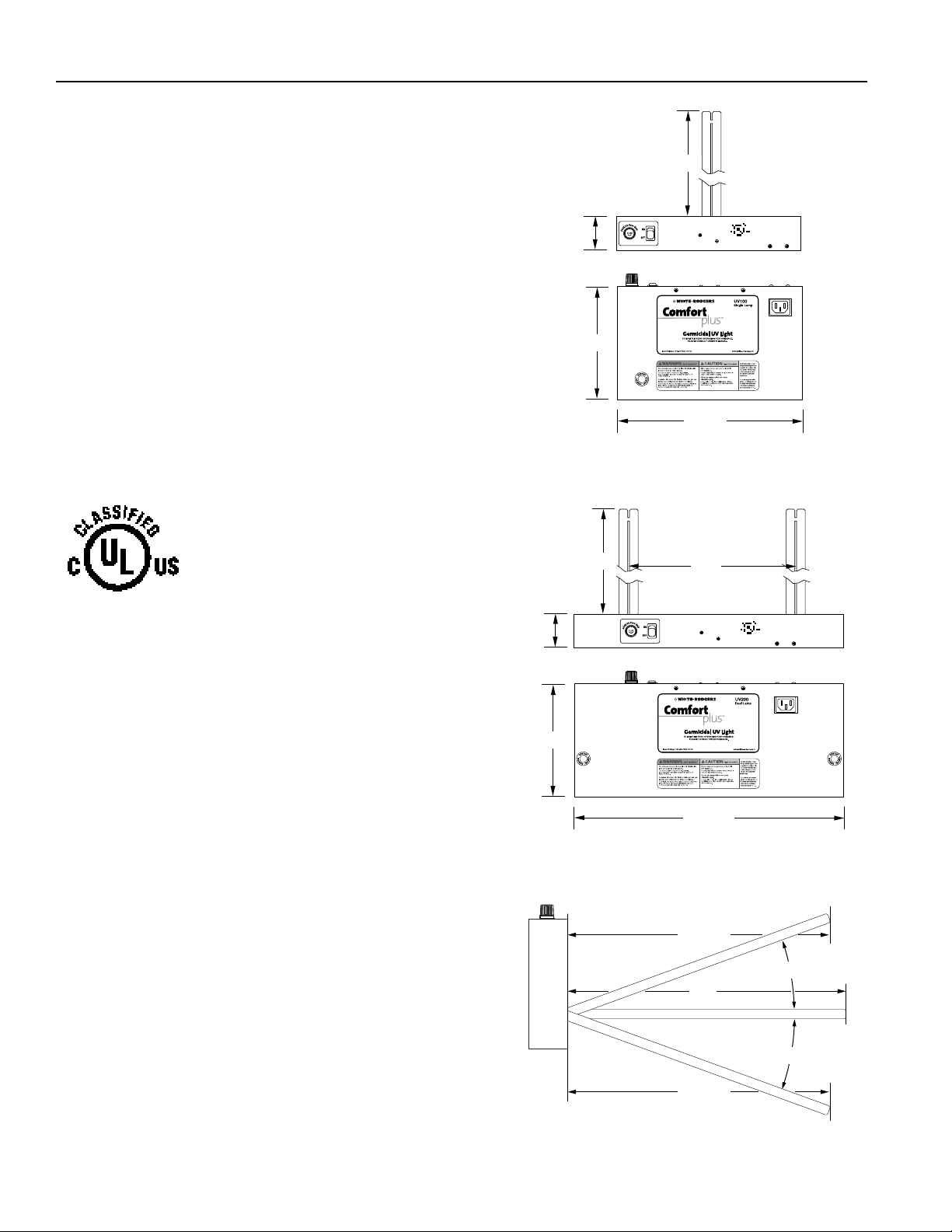
Base Dimensions:
Model UV100 - 6 7/8"L x 11 1/8"W x 2 1/16"H
Model UV200 - 6
7
/8"L x 14 3/16"W x 2 1/16"H
Weight:
Model UV100 - 4 1/2 lbs. Model UV200 - 6 3/4 lbs.
Electrical:
120V/240V, 50/60Hz, 1PH. 3A/250V fuse.
Operating Environment:
45° F - 150° F (Outside of duct.)
Listings:
FIFRA - File # 73316 (Federal Insecticide Fungicide Rodentcide Act)
UL Safety Agency - File #E213952
Specifications subject to change without notice.
Sizing
The UV100 is suitable for slab coil applications
3 tons or less, and 1200 CFM or less. Or
where space permits only a single lamp.
The UV200 is suitable for slab coil, A-coil, and
return air applications, where space permits
dual lamps.
Specifications
UV100
UV200
2.0625"
6.875"
15"
15"
11.125"
AIR DUCT MOUNTED ACCESSORY
WITH RESPECT TO ELECTRIC SHOCK,
FIRE AND CASUALTY HAZARDS ONLY
84SF
E213952
9"
2.0625"
6.875"
14.1875"
14.375"
15"
E213952
AIR DUCT MOUNTED ACCESSORY
WITH RESPECT TO ELECTRIC SHOCK,
FIRE AND CASUALTY HAZARDS ONLY
84SF
~20˚
~20˚
14.375"
UV100, UV200 INSTALLATION & OPERATION MANUAL
3
UV-C Light May Degrade Plastic and Rubber.
Shield exposed plastic drain pans, wire insulation, flex duct, or other plastic/rubber components from UV-C light.
INSTALLATION
This device installs in the air handling system.
Select a mounting location that will allow
enough clearance for the lamp to be installed
and replaced easily.
A 120V or 240V electrical outlet is required.
Optional 240V power cord (P/N 212107-00) is
required for 240V operation. Any modification
to the supplied power cord will void UL safety
listing and White-Rodgers warranty.
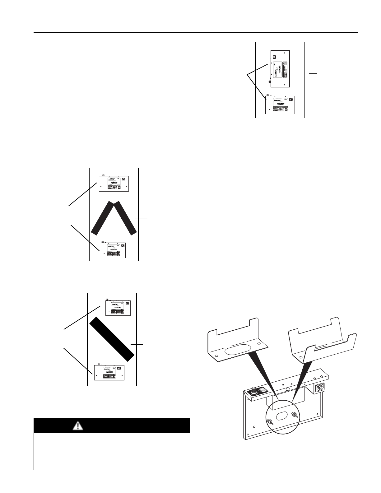
Selecting Lamp Bracket (Fig.4)
This device comes packaged with both a
straight-mount lamp bracket and an anglemount lamp bracket pre-installed. Choose the
mount appropriate for your application and
store the unused mount for possible future use.
Brackets are secured with knurled nuts.
Note: The angle bracket is useful in applications where
the duct is narrower than 16".
Fig. 1 Device may be mounted before or after A-coil in either horizontal or vertical air handling systems.
Fig. 4 Configure device to use either the straight-mount lamp
bracket or the angle-mount lamp bracket.
Fig. 2 Device may be mounted before or after slab coil in either
horizontal or vertical air handling systems.
Fig. 3 Mounting for airstream irradiation in return air flow.
CAUTION
Special Installation Notes
• Do not install in closet return grille applications.
• Do not install in outdoor applications.
• Do not expose wiring or plastic parts to UV-C light.
• Do not install beneath a humidifier.
A-Coil
Slab Coil
Return Air
Duct
Single or dual
lamp model.
Single or dual
lamp model.
Device may be
mounted vertically
or horizontally.
Straight-mount Bracket
Straight-mount bracket
should be mounted
with vertical side near
ballast.
Angle-mount Bracket
 Loading...