

Page 1
Electronic Air Cleaner
Model NumberModel Number
Model Number
Model NumberModel Number
SST
S
R
E
G
D
O
-R
E
IT
H
W
SST1000SST1000
SST1000
SST1000SST1000
SST1400SST1400
SST1400
SST1400SST1400
SST1600SST1600
SST1600
SST1600SST1600
SST2000SST2000
SST2000
SST2000SST2000
G
TIN
A
ER
P
O
T
H
LIG
N
O
F
F
O
OWNER’S MANUALOWNER’S MANUAL
OWNER’S MANUAL
OWNER’S MANUALOWNER’S MANUAL
••
InstallationInstallation
•
Installation
••
InstallationInstallation
••
OperationOperation
•
Operation
••
OperationOperation
••
Basic SST Service GuideBasic SST Service Guide
•
Basic SST Service Guide
••
Basic SST Service GuideBasic SST Service Guide
••
Technical Repair GuideTechnical Repair Guide
•
Technical Repair Guide
••
Technical Repair GuideTechnical Repair Guide
••
Repair PartsRepair Parts
•
Repair Parts
••
Repair PartsRepair Parts
Please read and familiarize yourself with the contents of this manual beforePlease read and familiarize yourself with the contents of this manual before
Please read and familiarize yourself with the contents of this manual before
Please read and familiarize yourself with the contents of this manual beforePlease read and familiarize yourself with the contents of this manual before
installing, operating or performing maintenance on the unit.installing, operating or performing maintenance on the unit.
installing, operating or performing maintenance on the unit.
installing, operating or performing maintenance on the unit.installing, operating or performing maintenance on the unit.
White-Rodgers is a division
of Emerson Electric Co.
www.white-rodgers.com
Printed in U.S.A.
PART NO. 37-6373CPART NO. 37-6373C
PART NO. 37-6373C
PART NO. 37-6373CPART NO. 37-6373C
Replaces 37-6373B
0238
Page 2
RULES FOR SAFERULES FOR SAFE
RULES FOR SAFE
RULES FOR SAFERULES FOR SAFE
INSTALLATION AND OPERATIONINSTALLATION AND OPERATION
INSTALLATION AND OPERATION
INSTALLATION AND OPERATIONINSTALLATION AND OPERATION
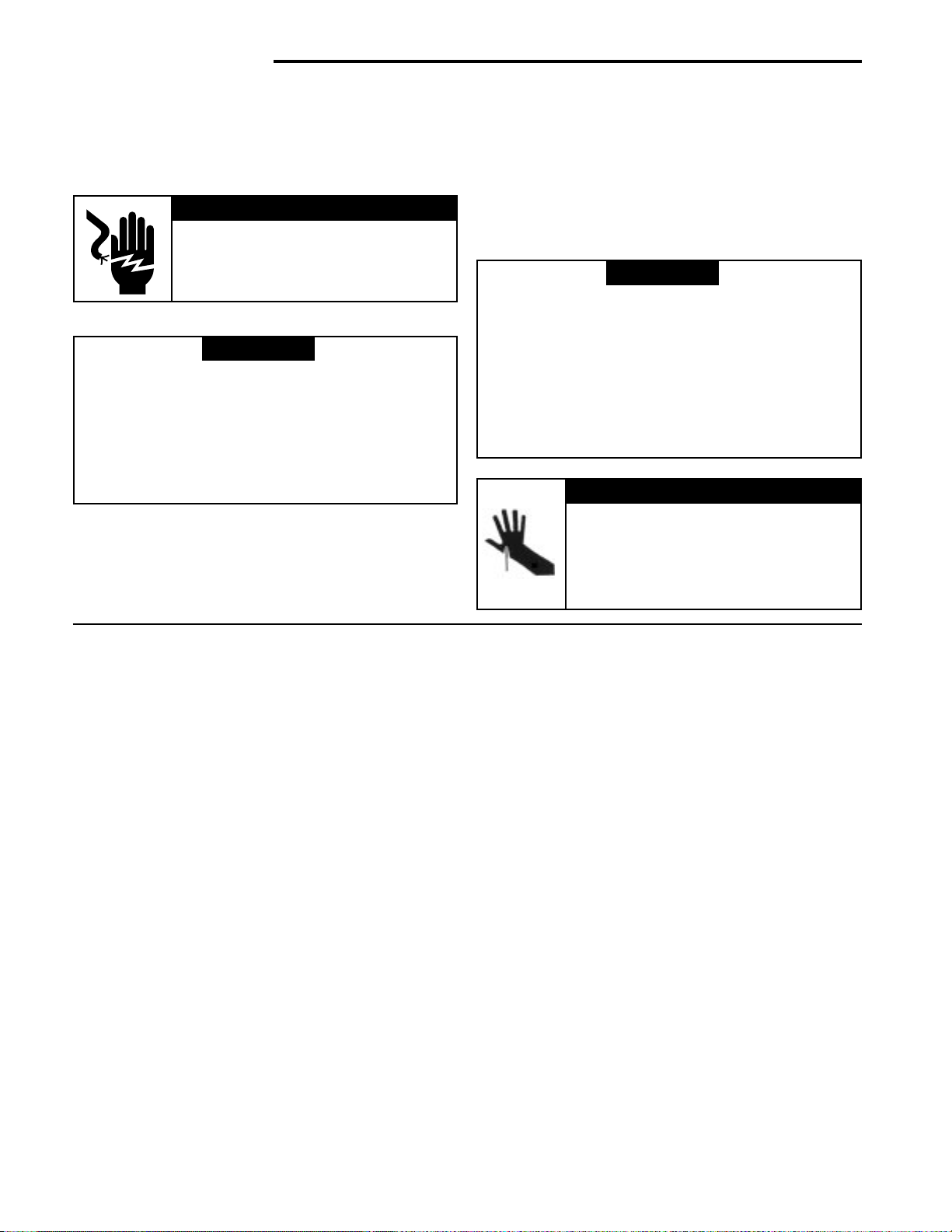
Please read instructions before installing and using the Electronic Air Cleaner. This will help you obtain the full benefit from
the Electronic Air Cleaner you have selected.
WARNINGWARNING
WARNING
!
WARNINGWARNING
▲
ELECTROCUTION HAZARDELECTROCUTION HAZARD
ELECTROCUTION HAZARD
ELECTROCUTION HAZARDELECTROCUTION HAZARD
Shut off power at fuse panel beforeShut off power at fuse panel before
Shut off power at fuse panel before
Shut off power at fuse panel beforeShut off power at fuse panel before
servicing. Failure to do so could resultservicing. Failure to do so could result
servicing. Failure to do so could result
servicing. Failure to do so could resultservicing. Failure to do so could result
in serious personal injury or death.in serious personal injury or death.
in serious personal injury or death.
in serious personal injury or death.in serious personal injury or death.
WARNINGWARNING
!
WARNING
WARNINGWARNING
▲
Do not attempt installation of this unit unless you areDo not attempt installation of this unit unless you are
Do not attempt installation of this unit unless you are
Do not attempt installation of this unit unless you areDo not attempt installation of this unit unless you are
familiar with the necessary tools, equipment, utilityfamiliar with the necessary tools, equipment, utility
familiar with the necessary tools, equipment, utility
familiar with the necessary tools, equipment, utilityfamiliar with the necessary tools, equipment, utility
connections and potential hazards.connections and potential hazards.
connections and potential hazards.
connections and potential hazards.connections and potential hazards.
Installation should be performed only by a qualifiedInstallation should be performed only by a qualified
Installation should be performed only by a qualified
Installation should be performed only by a qualifiedInstallation should be performed only by a qualified
service provider.service provider.
service provider.
service provider.service provider.
Failure to do so could result in reduced performanceFailure to do so could result in reduced performance
Failure to do so could result in reduced performance
Failure to do so could result in reduced performanceFailure to do so could result in reduced performance
of the unit, serious personal injury or death.of the unit, serious personal injury or death.
of the unit, serious personal injury or death.
of the unit, serious personal injury or death.of the unit, serious personal injury or death.
1. Read the Owners Manual and the Rules for Safe
Operation carefully. Failure to follow these rules and
instructions could cause a malfunction of filter or
unsatisfactory service.
2. Follow a regular service and maintenance schedule
for efficient operation.
3. Unit must run for one full hour after installation. This
will allow the collecting cells to reach peak efficiency.
4. If Air Flow Monitor is required, order F859-0381 kit.
WARNINGWARNING
!
WARNING
WARNINGWARNING
▲
Installation of this unit must comply with localInstallation of this unit must comply with local
Installation of this unit must comply with local
Installation of this unit must comply with localInstallation of this unit must comply with local
electric codes or other applicable codes.electric codes or other applicable codes.
electric codes or other applicable codes.
electric codes or other applicable codes.electric codes or other applicable codes.
Review and understand local codes prior toReview and understand local codes prior to
Review and understand local codes prior to
Review and understand local codes prior toReview and understand local codes prior to
installation.installation.
installation.
installation.installation.
Do not use this apparatus in an explosiveDo not use this apparatus in an explosive
Do not use this apparatus in an explosive
Do not use this apparatus in an explosiveDo not use this apparatus in an explosive
atmosphere.atmosphere.
atmosphere.
atmosphere.atmosphere.
Failure to do so could result in serious personalFailure to do so could result in serious personal
Failure to do so could result in serious personal
Failure to do so could result in serious personalFailure to do so could result in serious personal
injury or death.injury or death.
injury or death.
injury or death.injury or death.
CAUTIONCAUTION
!
CAUTION
CAUTIONCAUTION
▲
CABINET AND CELLS MAY CONTAINCABINET AND CELLS MAY CONTAIN
CABINET AND CELLS MAY CONTAIN
CABINET AND CELLS MAY CONTAINCABINET AND CELLS MAY CONTAIN
SHARP EDGES.SHARP EDGES.
SHARP EDGES.
SHARP EDGES.SHARP EDGES.
Use care when servicing unit or handl-Use care when servicing unit or handl-
Use care when servicing unit or handl-
Use care when servicing unit or handl-Use care when servicing unit or handling cells. Failure to do so could resulting cells. Failure to do so could result
ing cells. Failure to do so could result
ing cells. Failure to do so could resulting cells. Failure to do so could result
in minor personal injury.in minor personal injury.
in minor personal injury.
in minor personal injury.in minor personal injury.
TABLE OF CONTENTSTABLE OF CONTENTS
TABLE OF CONTENTS
TABLE OF CONTENTSTABLE OF CONTENTS
Rules for Safe Installation and Operation ............2
How the Air Cleaner Works..................................3
Construction of the Air Cleaner ............................ 3
Preinstallation.......................................................4
Installation ............................................................6
Wiring Instructions ...............................................7
Operation ............................................................. 8
Maintenance and Washing...................................8
Specifications .......................................................9
Basic SST Service Guide...................................10
Technical Repair Guide......................................11
Air Cleaner Retrofit (Upgrade) Kit Installation....13
Repair Parts .......................................................14
Wash Reminder ................................................. 16
DID YOU GET THE RIGHT SIZEDID YOU GET THE RIGHT SIZE
DID YOU GET THE RIGHT SIZE
DID YOU GET THE RIGHT SIZEDID YOU GET THE RIGHT SIZE
AIR CLEANERAIR CLEANER
AIR CLEANER
AIR CLEANERAIR CLEANER
Model SST1000 Model SST1000
Model SST1000 is designed for heating or cooling blow-
Model SST1000 Model SST1000
ers delivering 600 to 1200 cubic feet of air per minute
(cfm.)
Model SST1400 Model SST1400
Model SST1400 is designed for heating or cooling blow-
Model SST1400 Model SST1400
ers delivering 1000 to 1600 cfm.
Model SST1600 Model SST1600
Model SST1600 is designed for heating or cooling blow-
Model SST1600 Model SST1600
ers delivering 1000 to 2000 cfm.
Model SST2000 Model SST2000
Model SST2000 is designed for heating or cooling blow-
Model SST2000 Model SST2000
ers delivering 1600 to 2200 cfm.
See specifications on page 9.
BASIC TOOLS REQUIREDBASIC TOOLS REQUIRED
BASIC TOOLS REQUIRED
BASIC TOOLS REQUIREDBASIC TOOLS REQUIRED
Tin Snip
Screwdriver
Rule or Tape Measure
Drill
2
Page 3
ABC
Dirty Air In Clean Air Out
Cabinet
Pre-Filters
Handle
Contact
Button
Contact
Button
Collecting Cells
Power Pack
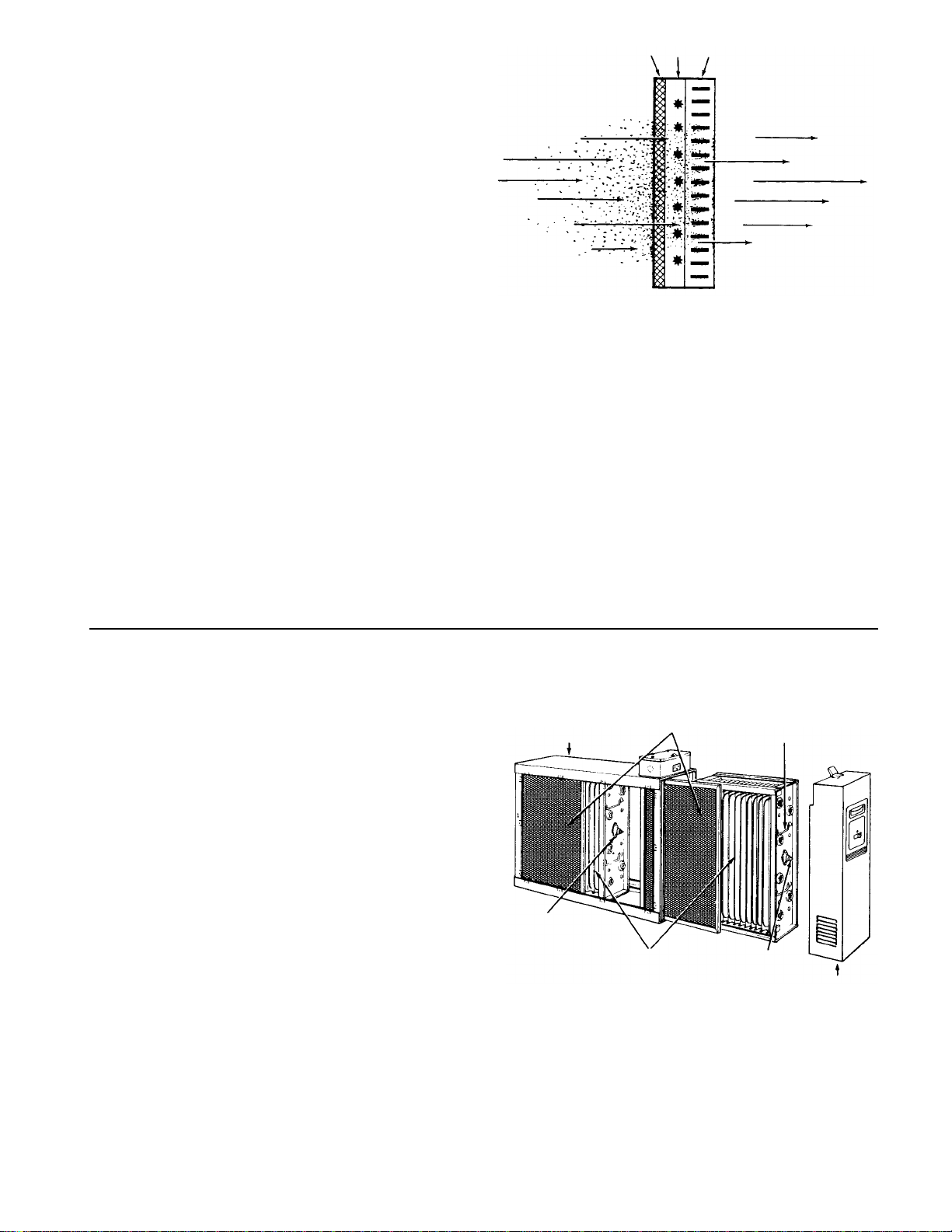
HOW THE AIR CLEANER WORKSHOW THE AIR CLEANER WORKS
HOW THE AIR CLEANER WORKS
HOW THE AIR CLEANER WORKSHOW THE AIR CLEANER WORKS
Dirt particles flowing through the ducts (Figure 1) first enters
the pre-filters (A) where large particles (hair, lint, etc.) are
trapped. Smaller particles (smoke, dust, pollen, etc.) pass
through these pre-filters and enter the ionizing section (B).
Here each tiny particle receives a positive electrical charge.
These charged particles then enter the collecting section
(C). This section consists of a series of aluminum plates
which are alternately charged negative and positive.
The positive charge of the particles cause them to be
repelled by the positive plates and attracted to the negative
plates where they are collected . . . just as a magnet
attracts iron filings.
Clean-filtered air re-enters the supply duct system.
White Dust (Lint)White Dust (Lint)
White Dust (Lint)
White Dust (Lint)White Dust (Lint)
An Electronic Air Cleaner is designed to collect two major
types of contaminants: ➀ Irritants (Pollens, Spores, Molds,
Bacteria, etc.) and ➁ Black Soiling Contaminants (Dirt and
Smoke particles).
The residue on the collecting plates of an electronic air
cleaner is black, indicating it is removing dirt from the air
stream. After installing an air cleaner you may notice white
dust (typically, long linty particles or fibers – from carpets,
cotton materials or drapery fabrics). This material is not
collected by the air cleaner because it does not contain the
irritants or soiling contaminants listed above or settles out of
the air before reaching the air cleaner. The presence of
white dust does not indicate an air cleaner requires service.
Figure 1Figure 1
Figure 1
Figure 1Figure 1
Carbon (Charcoal) FiltersCarbon (Charcoal) Filters
Carbon (Charcoal) Filters
Carbon (Charcoal) FiltersCarbon (Charcoal) Filters
Odors are gas molecules, not particles. They cannot be
removed by an Electronic Air Cleaner or by any other
filtration media designed to remove airborne particles.
However, some gases can be absorbed by an activated
carbon filter or diluted with fresh outdoor air. When odors
are present, the addition of charcoal filters will neutralize
odors, such as cooking odors, pet odors, cigar and cigarette odors, ozone, etc. Optional charcoal filters are
available for your Air Cleaner. Refer to the parts list for the
charcoal filter part number for your Air Cleaner. Charcoal
filters require replacement. They cannot be washed. While
there is no rule of thumb for how often they should be
changed, you can use your best judgement based on the
odors you perceive in your environment.
CONSTRUCTION OF THE AIR CLEANERCONSTRUCTION OF THE AIR CLEANER
CONSTRUCTION OF THE AIR CLEANER
CONSTRUCTION OF THE AIR CLEANERCONSTRUCTION OF THE AIR CLEANER
Not only is your air cleaner easy to install, it is also easy to
operate and maintain. Its basic components, and their
functions, are as follows: (See Figure 2)
Cabinet Cabinet
Cabinet - mounts to existing duct work and houses the
Cabinet Cabinet
collecting cells and pre-filters.
Collecting Cells Collecting Cells
Collecting Cells - are made in two sections and perform
Collecting Cells Collecting Cells
the actual collecting of dust, dirt, and other impurities from the air. They contain the ionizing and
collection sections described above.
Each cell must be installed with the ionizing wires
on the air entering side. Each cell must be oriented
with the handles and contact button (Figure 2)
toward the operator.
Pre-filters Pre-filters
Pre-filters - are in two sections which are interchangeable.
Pre-filters Pre-filters
Power Pack- Power Pack-
Power Pack- contains operating and power on lights as well
Power Pack- Power Pack-
They serve as a pre-filter to trap large particles
such as hair and lint before they can enter the cell
sections.
as the solid state components that convert the 120
volt power supply to the high-voltage, direct current
required for the collecting cell.
Figure 2Figure 2
Figure 2
Figure 2Figure 2
3
Page 4
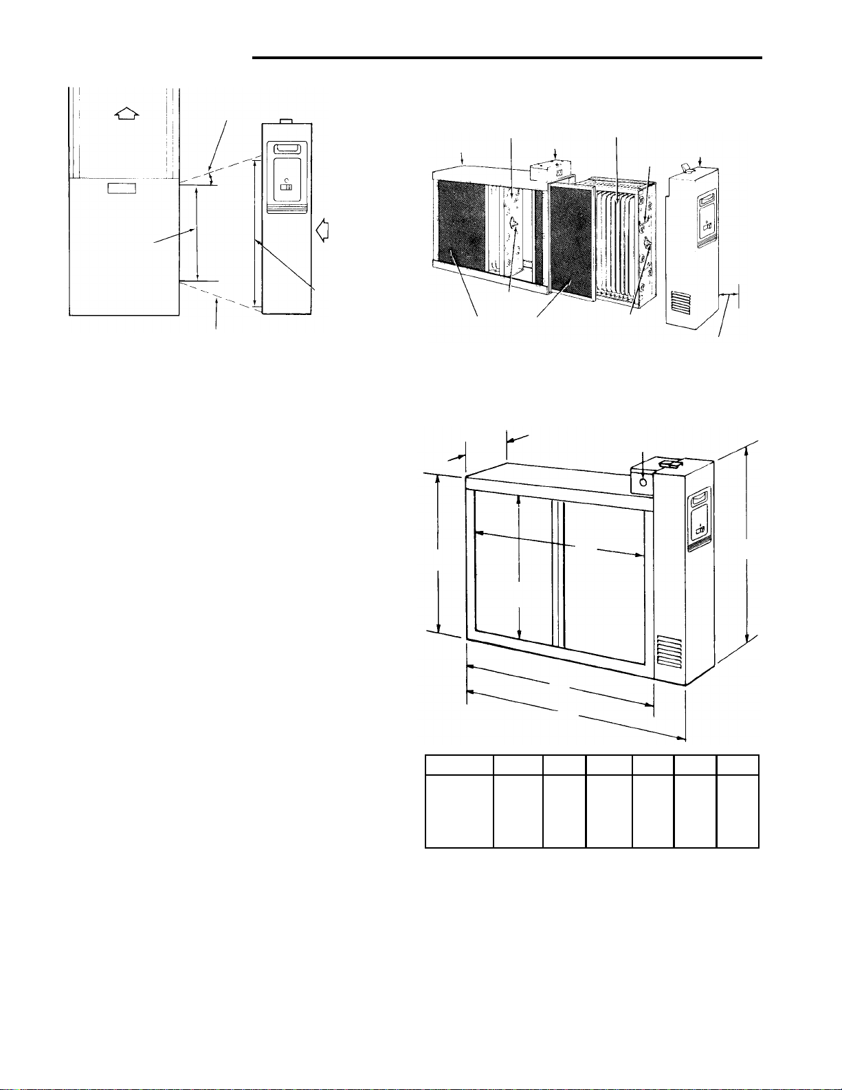
SST1000 24 3/4 21 5/16 18 5/8 13 9/16 16 7/16 19 1/16
SST1400 29 11/16 26 1/4 23 5/8 13 9/16 16 7/16 19 1/16
SST1600 25 1/2 21 5/16 18 5/8 17 3/4 20 5/8 23 3/8
SST2000 29 11/16 26 1/4 23 5/8 17 3/4 20 5/8 23 3/8
MODEL NO. A B C D E F
PREINSTALLATIONPREINSTALLATION
PREINSTALLATION
PREINSTALLATIONPREINSTALLATION
Not to Exceed 20
Air Flow
Furnace
Opening
Electronic
Air Cleaner
Opening
Furnace
Transition Section
(if Needed)
Electronic
Air Cleaner
Figure 3
LOCATING THE AIR FILTERLOCATING THE AIR FILTER
LOCATING THE AIR FILTER
LOCATING THE AIR FILTERLOCATING THE AIR FILTER
Your air filter must be mounted in the return air duct of a
central forced-air system, on the air entering side of your
furnace. (See Figure 3 for example.)
Select a location that meets the following:
1. The face of the cell will be at a right angle to the air
stream.
2. Allow the following clearances to permit removal of
cells and pre-filters: (See Figures 4 and 5)
Model SST1000 - 14 inches
Model SST1400 - 15 inches
Model SST1600 - 14 inches
Model SST2000 - 15 inches
For complete dimension data refer to Figure 5.
3. The air filter is not to be placed in the discharge of
either the heating or cooling unit.
IMPORTANT: IMPORTANT:
4.
IMPORTANT: If atomizing spray type humidifier is
IMPORTANT: IMPORTANT:
used, it must be installed downstream from the air
filter.
If your furnace duct system has a pre-installed boot,
discard front cover of boot and slide the air cleaner
component inside the boot. For installation of Air Cleaner
Retrofit (ACR) kits, see page 13.
If furnace opening cannot be enlarged to required size, a
transition sheet metal section must be used. Transition
must be planned for each job. Reduction should not be
more than 4 inches per linear foot, approximately 20
angular degrees (Figure 3).
DIRECTION OF AIR FLOW THROUGH THEDIRECTION OF AIR FLOW THROUGH THE
DIRECTION OF AIR FLOW THROUGH THE
DIRECTION OF AIR FLOW THROUGH THEDIRECTION OF AIR FLOW THROUGH THE
AIR CLEANERAIR CLEANER
AIR CLEANER
AIR CLEANERAIR CLEANER
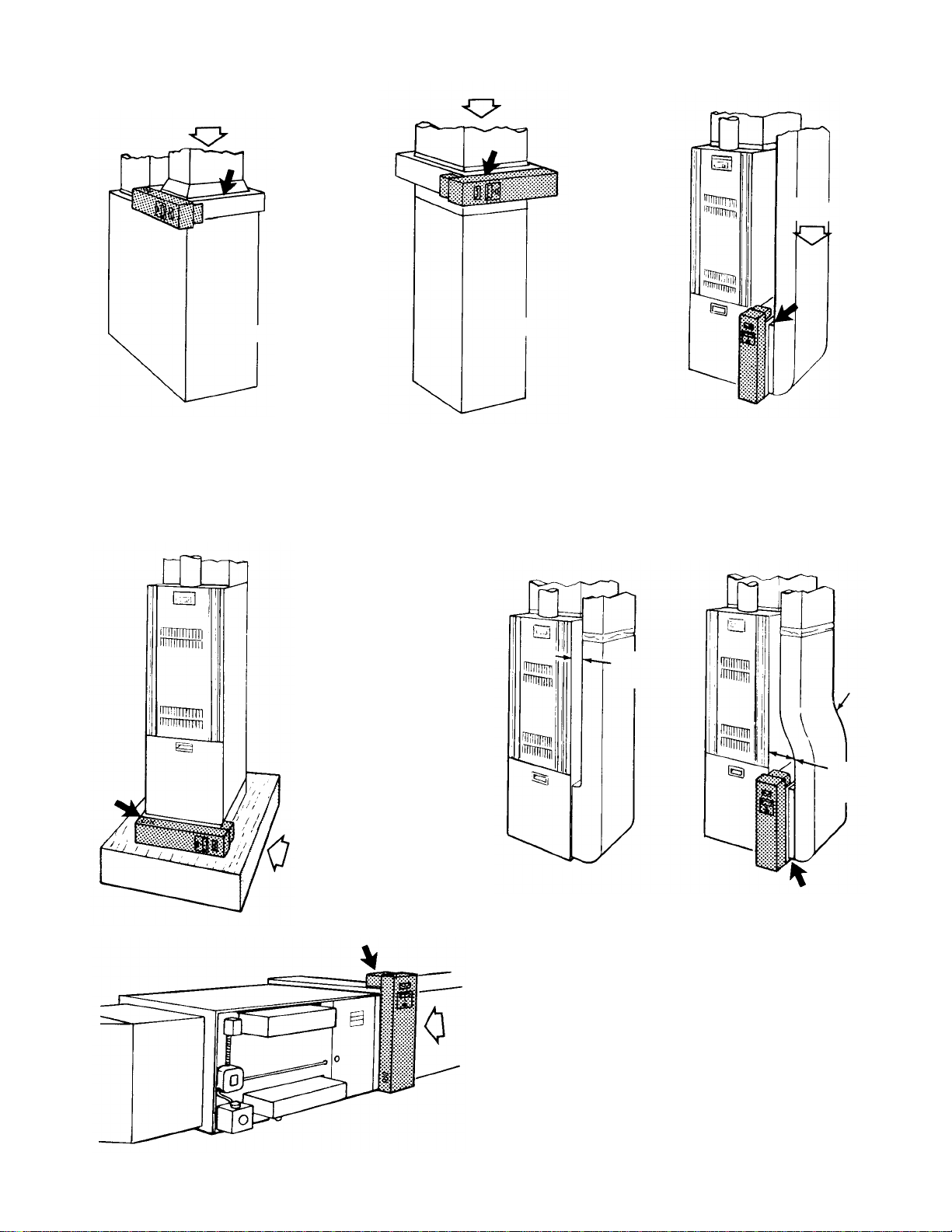
Your air cleaner is shipped from the factory with air flow
from left-to-right. If this air flow is suitable for the installation, no further changes need to be made (Figure 4). For
right-to-left air flow, remove both pre-filter and cell sec-
Air Flow
(Interchangeable)
Collecting Cell
Cabinet
Contact
Button
Pre-Filters
(Interchangeable)
Outlet Box
(Interchangeable)
Collecting Cell
Handle
Contact
Button
Removal Clearance
Power Pack
See text for Cell
Figure 4
Knockouts for
6 7/8"
E
3/4" Conduit
(three sides)
C
D
B
A
Figure 5
tions. Turn cells upside down (with the same end facing
the cabinet opening). This will locate the ionizing wires at
the right, and both contact buttons and cell handles will be
facing the power door. Air flow direction must agree with
arrow embossed on end of collecting cells.
After installing the cell sections, install pre-filters in cabinet tracks on the right. This will again place the pre-filters
on the air entering side (on the same side as ionizing
wires).
4
F
Page 5
TYPICAL MOUNTING POSITIONSTYPICAL MOUNTING POSITIONS
Air Flow
Figure 8
TYPICAL MOUNTING POSITIONS
TYPICAL MOUNTING POSITIONSTYPICAL MOUNTING POSITIONS
Air Flow
Air Flow
Rear View
Figure 6
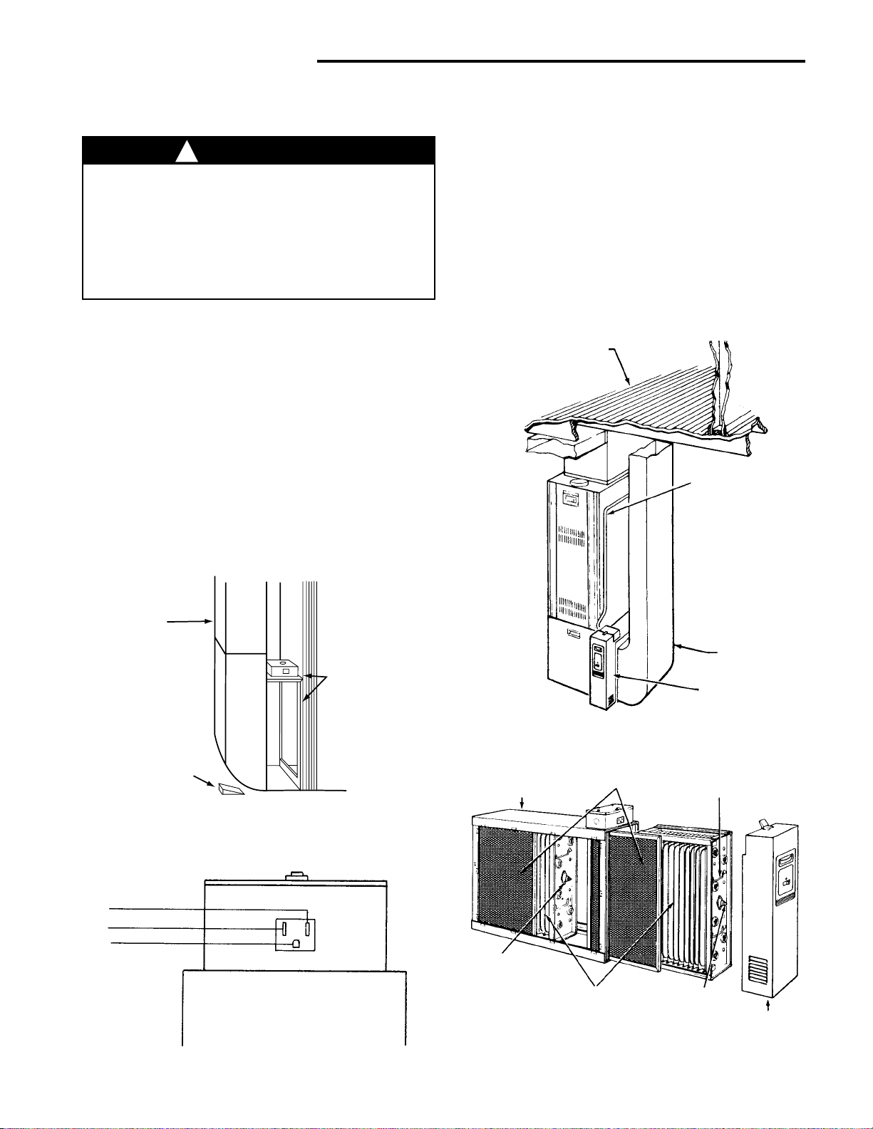
BASEMENT FURNACEBASEMENT FURNACE
BASEMENT FURNACE
BASEMENT FURNACEBASEMENT FURNACE
(LOWBOY) (Figure 6)(LOWBOY) (Figure 6)
(LOWBOY) (Figure 6)
(LOWBOY) (Figure 6)(LOWBOY) (Figure 6)
Cleaner is mounted hori-
zontally in return plenum,
just above furnace.
Figure 7
COUNTERFLOWCOUNTERFLOW
COUNTERFLOW
COUNTERFLOWCOUNTERFLOW
FURNACE (Figure 7)FURNACE (Figure 7)
FURNACE (Figure 7)
FURNACE (Figure 7)FURNACE (Figure 7)
Cleaner is mounted horizon-
tally in return duct or plenum,
just above furnace.
HIGHBOY FURNACEHIGHBOY FURNACE
HIGHBOY FURNACE
HIGHBOY FURNACEHIGHBOY FURNACE
(Figure 9)(Figure 9)
(Figure 9)
(Figure 9)(Figure 9)
Installation beneath furnace.
Cleaner mounts horizontally,
where return air enters from
below. Raise furnace and install beneath base.
Rear View
HIGHBOY FURNACEHIGHBOY FURNACE
HIGHBOY FURNACE
HIGHBOY FURNACEHIGHBOY FURNACE
(Figure 8)(Figure 8)
(Figure 8)
(Figure 8)(Figure 8)
Side installation. Cleaner
is mounted vertically,
where return air enters
side inlet of furnace.
Less than
7 Inches
Offset
At Least
9 Inches
Figure 9
Air Flow
Figure 11
OFFSET INSTALLATIONOFFSET INSTALLATION
OFFSET INSTALLATION
OFFSET INSTALLATIONOFFSET INSTALLATION
(Figure 10)(Figure 10)
(Figure 10)
(Figure 10)(Figure 10)
Typical use of duct offset to match air filter opening.
If duct connection to furnace allows less than nine
inches for mounting the air cleaner, shorten the
lateral trunk, or attach an offset fitting to the elbow.
Air Flow
HORIZONTAL FURNACEHORIZONTAL FURNACE
HORIZONTAL FURNACE
HORIZONTAL FURNACEHORIZONTAL FURNACE
(Figure 11)(Figure 11)
(Figure 11)
(Figure 11)(Figure 11)
Cleaner is mounted vertically
in the return duct near furnace.
5
Figure 10
Page 6
Air Flow
Turning
Vanes
Figure 14
INSTALLATIONINSTALLATION
INSTALLATION
INSTALLATIONINSTALLATION
REMOVE OLD FILTER AND DISCARDREMOVE OLD FILTER AND DISCARD
REMOVE OLD FILTER AND DISCARD
REMOVE OLD FILTER AND DISCARDREMOVE OLD FILTER AND DISCARD
(Figure 12)(Figure 12)
(Figure 12)
(Figure 12)(Figure 12)
NOTE: This filter may be mounted in the furnace compartment.
CLEAN BLOWER COMPARTMENTCLEAN BLOWER COMPARTMENT
CLEAN BLOWER COMPARTMENT
CLEAN BLOWER COMPARTMENTCLEAN BLOWER COMPARTMENT
It is suggested that the furnace blower compartment,
blower and blower housing be cleaned to ensure clean air
circulation.
Figure 12
INSTALLATIONINSTALLATION
INSTALLATION
INSTALLATIONINSTALLATION
The following is a typical installation of the air cleaner on
a “Highboy” furnace (Figure 8).
1. Place the air filter cleaner on the floor. Stand it upright
with the power door facing you (Figure 4). If a
horizontal installation is being planned, lay the cleaner
on its side, this will help you to visualize the relative
location of all parts.
Allow ample space for wiring and servicing the power
supply box (Figure 13).
2. Release the latch, remove the power pack (by grasping handle and pulling power pack away from cabinet)
and set it aside. Remove the collecting cells and prefilters. Set pre-filters and cells aside in a safe location
until the cabinet is installed.
3. Set the cabinet next to the furnace. If necessary,
enlarge the opening in the furnace (if possible) to
match the opening in the cabinet.
If the furnace opening cannot be enlarged, a transition fitting should be used. (Figure 3).
The cabinet can be attached directly (Figure 13), or
a starting collar can first be fitted to the furnace inlet.
A butt or slip joint can be used.
Securely attach the cabinet to furnace inlet, using at
least two of the mounting holes on each side of the
cabinet.
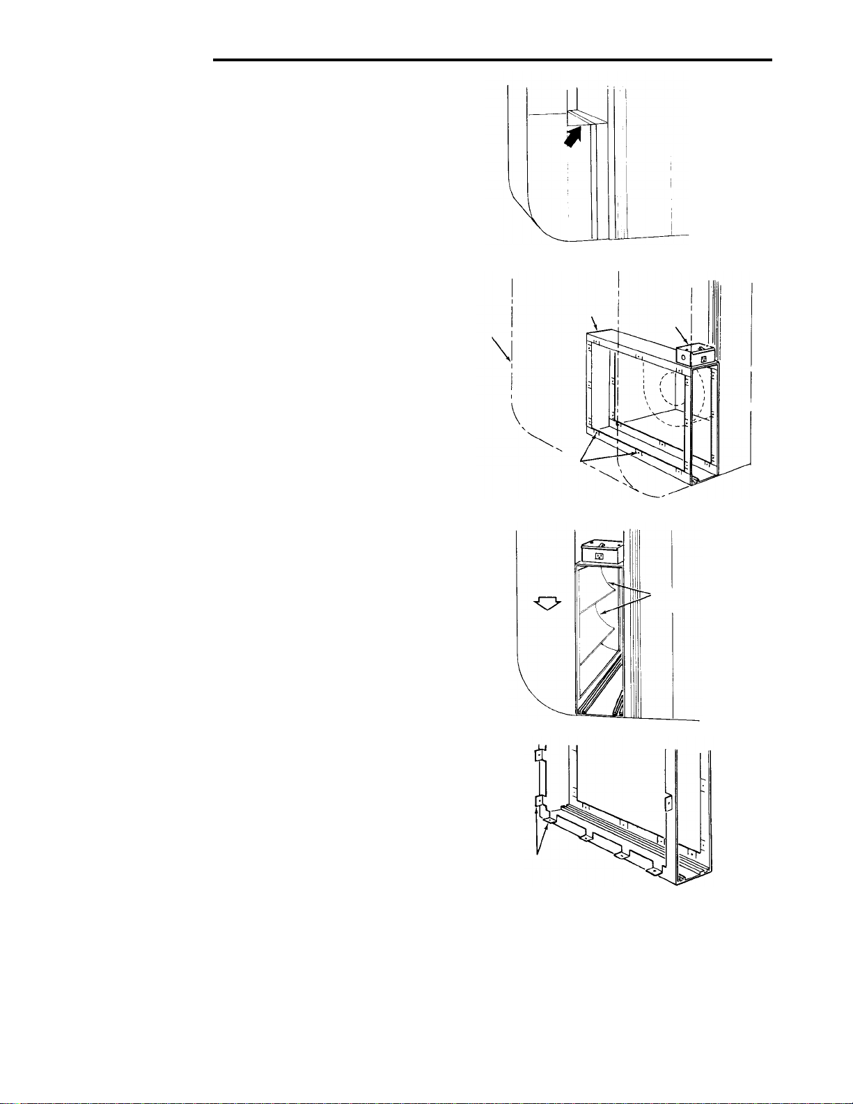
4. Using butt joint, attach duct work (normally an elbow)
to the upstream side of air cleaner cabinet. (Note the
use of the sheet metal turning vanes inside the elbow
to improve air distribution over the face of the cells.)
(Figure 14)
NOTE: NOTE:
NOTE: An optional method of attaching duct work to the
NOTE: NOTE:
cabinet is to modify the cabinet (Figure 15) by bending the
tabs outward at a 90° angle and attaching duct work to
tabs.
Transition FittingsTransition Fittings
Transition Fittings
Transition FittingsTransition Fittings
If the air duct does not fit the cabinet opening, a transition
fitting should be used. Gradual transitions are preferred
for greatest efficiency. Not more than four inches per
linear foot (approximately 20° angle) should be allowed
(Figure 3).
Power
Frame
Duct
Mounting
Holes
Optional method
(Bend tabs outward at 90˚ angle)
5. Connect the vertical duct section to the elbow. Wedge
a wood block between floor and elbow for support
(Figure 16).
6. Seal all joints in the return air system downstream
from the air cleaner with duct tape to prevent dust
from entering the air stream. Tape is usually applied
on the outside of ducts, but may also be applied on the
inside, or both.
Supply
Box
Figure 13
Figure 15
6
Page 7
Cabinet
Pre-Filters
Handle
Contact
Button
Contact
Button
Collecting Cells
Power Pack
WIRING INSTRUCTIONSWIRING INSTRUCTIONS
WIRING INSTRUCTIONS
WIRING INSTRUCTIONSWIRING INSTRUCTIONS
7. With the cabinet installed, the air cleaner can now be
wired to electrical input source.
!
WARNING
Installation of this unit must comply with localInstallation of this unit must comply with local
Installation of this unit must comply with local
Installation of this unit must comply with localInstallation of this unit must comply with local
electric codes or other applicable codes.electric codes or other applicable codes.
electric codes or other applicable codes.
electric codes or other applicable codes.electric codes or other applicable codes.
Review and understand local codes prior to in-Review and understand local codes prior to in-
Review and understand local codes prior to in-
Review and understand local codes prior to in-Review and understand local codes prior to installation.stallation.
stallation.
stallation.stallation.
Failure to do so could result in serious personalFailure to do so could result in serious personal
Failure to do so could result in serious personal
Failure to do so could result in serious personalFailure to do so could result in serious personal
injury or death.injury or death.
injury or death.
injury or death.injury or death.
8. This air cleaner unit has no air flow monitor installed,
it does require electrical wiring through the furnace
controls. Connect wiring to the furnace control terminals. (EAC-H) for power, (EAC-N) for neutral, and
connect metal frame of EAC to ground. If air flow
monitor is required for operation, order F859-0381 Air
Flow kit. Install kit and connect a 120 VAC 60 Hz input
circuit. A 20 amp circuit is more than adequate.
9. Remove junction box cover and install the required
bushing into the 3/4 in. Knock out. With the supply
voltage turned off, route three (3) wires into junction
box for connections. (See Fig. 17.)
Insure all wires are clamped, wire connectors properly installed and grommets used to prevent wire
abrasion.
10. With the cabinet Installed, reinstall pre-filter(s) and
collecting cell(s) (Figure 19).
NOTE: The contact button and handles on the cell
must be facing you and ionizing wires must be on the
air intake side.
11. Install the power pack as follows:
Engage the lip on lower inside edge of power pack in
the flange on cabinet and carefully close the power
pack, making sure that the electrical connector prongs
on the power pack enter the slots in the socket on
cabinet. When the power pack is fully in place, engage the latch and snap it closed.
Floor
Conduit
Vertical
Section
Wood Block
Hot
Neutral
Grounding
Conductor
Figure 16
Front View
Figure 17
Tape All
Joints
Duct
Electronic
Air Cleaner
Figure 18
Figure 19
7
Page 8
OPERATIONOPERATION
OPERATION
OPERATIONOPERATION
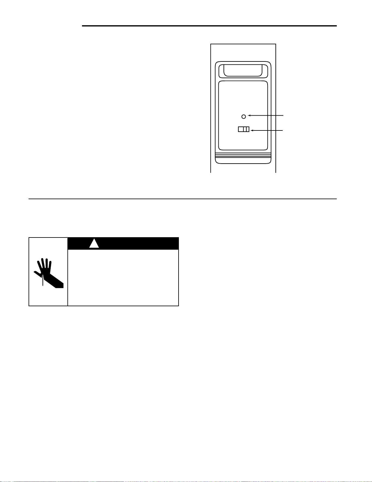
1. With the 120 VAC power turned on at the circuit
breaker for the furnace, push the air cleaner ON-OFF
switch to the “ON” position (Figure 20).
2. With the furnace blower running, the air cleaner will
be operating. An arcing or “snapping” sound may be
heard. This will occur occasionally, however the unit
is operating properly.
3. With the furnace blower running, the Operating Light
should be ON. If the Operating Light is not ON this
signifies that the cells need washing, or that trouble
exists in the unit.
If, after washing the cells, the Operating Light stays off,
the cell could be wet, improperly placed in the cabinet or
may need servicing.
NOTE: NOTE:
NOTE: An occasional flicker of the light accompanied by
NOTE: NOTE:
harmless sparking or snapping noise may occur. This is
caused by trapping large particles of dirt. If arcing is
continuous, the cells should be washed or checked for
service problems see Basic SST Service Guide.
Operating
Light
On-Off
Switch
Figure 20
MAINTENANCE AND WASHINGMAINTENANCE AND WASHING
MAINTENANCE AND WASHING
MAINTENANCE AND WASHINGMAINTENANCE AND WASHING
!
CAUTION
CABINET AND CELLS MAY CON-CABINET AND CELLS MAY CON-
CABINET AND CELLS MAY CON-
CABINET AND CELLS MAY CON-CABINET AND CELLS MAY CONTAIN SHARP EDGES.TAIN SHARP EDGES.
TAIN SHARP EDGES.
TAIN SHARP EDGES.TAIN SHARP EDGES.
Use care when servicing unit orUse care when servicing unit or
Use care when servicing unit or
Use care when servicing unit orUse care when servicing unit or
handling cells.handling cells.
handling cells.
handling cells.handling cells.
Failure to do so could result inFailure to do so could result in
Failure to do so could result in
Failure to do so could result inFailure to do so could result in
minor personal injury.minor personal injury.
minor personal injury.
minor personal injury.minor personal injury.
For maximum efficiency your air cleaner cell(s) and prefilter(s) should be inspected once a month and cleaned
when necessary. Cleaning will usually be required every
one to three months, depending upon the particular
household circumstances. When cleaning is required the
following procedure should be used:
CLEANING THE CELLSCLEANING THE CELLS
CLEANING THE CELLS
CLEANING THE CELLSCLEANING THE CELLS
1. Turn the air moving system “OFF.”
2. Push the ON-OFF switch on the power pack to the
“OFF” position (Figure 20). Wait 15 seconds and both
the power pack and the collecting cell(s) will be
automatically discharged.
3. Release the latch on top of power pack and pull the
power pack straight away from cabinet at the top.
Then lift pack out of ledge at bottom edge of cabinet.
Set power pack aside.
4. Remove the cell(s) and pre-filter(s) from cabinet.
Using a solution of warm water and low sudsing
detergent, soak cell(s) and pre-filter(s) for 20 to 30
minutes.
NOTE: NOTE:
NOTE: Ionizing wires may become coated causing
NOTE: NOTE:
loss of cleaning ability by the collecting cell. Using a
damp cloth, wipe each ionizing wire, exercising care
not to damage them.
5. Remove the cell(s) and pre-filter(s) from solution and
rinse thoroughly with clean water.
6 Allow cell(s) and pre-filter(s) to drip dry for a
mum of 2 hours. mum of 2 hours.
mum of 2 hours. Cell(s) and pre-filter(s) may be
mum of 2 hours. mum of 2 hours.
tipped at a slight angle to expedite the drip-dry
process.
7. Reinstall the cell(s) and pre-filter(s) in the cabinet.
8. Replace the power pack. Turn furnace fan on. After
30 minutes push ON-OFF switch on the power pack
to the “ON” position.
A moderate amount of arcing or “snapping” may
occur at this time, which will indicate that the cell(s)
are still damp. If the noise is objectionable, push the
ON-OFF switch to the “OFF” position and allow
additional time for cell(s) and pre-filter(s) to dry. In
some cases the Operating Light will remain OFF
during this initial activation of the air cleaner, and this
would indicate that the cell(s) are not completely dry.
The Operating Light should remain ON while the
furnace fan is running once the drying is complete.
mini-mini-
mini-
mini-mini-
8
Page 9
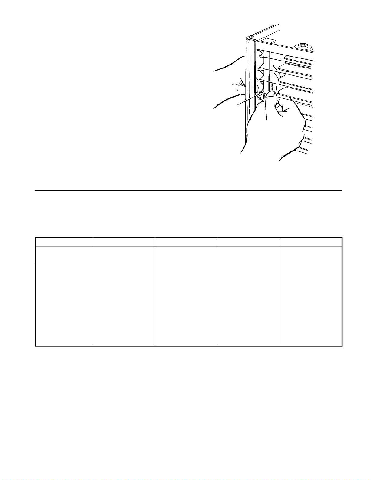
REPLACING AN IONIZING WIREREPLACING AN IONIZING WIRE
REPLACING AN IONIZING WIRE
REPLACING AN IONIZING WIREREPLACING AN IONIZING WIRE
If an ionizing wire should break, it can be replaced as
follows:
1. Remove all pieces of broken wire. Make sure supports at each end are in good condition and not bent
out of shape.
2. Hook the new wire onto the support at one end.
3. Hold your finger against the support at the other end
(Figure 21) and hold the ionizing wire between thumb
and forefinger as shown or use needle nose pliers.
Press inward on spring support. Hook end of wire
over small tab at end of support and release. Make
sure wire is securely anchored at each end.
Support
Ionizing
Wire
Figure 21
SPECIFICATIONSSPECIFICATIONS
SPECIFICATIONS
SPECIFICATIONSSPECIFICATIONS
SPECIFICATIONS SST1000 SST1400 SST1600 SST2000
Rated Capacity 600 - 1200 cfm 1000 - 1600 cfm 1000 - 2000 cfm 1600 - 2200 cfm
Max. Pressure Drop .08 in. W.G. .08 in. W.G. .12 in. W.G. .09 in. W.G.
Cell Weight (2) 7 lbs. each (2) 9 lbs. each (2) 9 lbs. each (2) 9 lbs. each
Power Pack Weight 9 lbs. 9 lbs. 10 lbs. 10 lbs.
Unit Weight 35 lbs. 42 lbs. 38 lbs. 45 lbs.
Power Consumption 40 Watts (Max) 40 Watts (Max) 40 Watts (Max) 40 Watts (Max)
Electrical Input 120 VAC 60 hz. 120 VAC 60 hz. 120 VAC 60 hz. 120 VAC 60 hz.
Electrical Output 1.0 Ma 1.2 Ma 1.5 Ma 1.7 Ma
@ 6450 VDC (nom)
Max. Ozone Output .05 ppm .05 ppm .05 ppm .05 ppm
Temperature Rating 40 F to 125 F 40 F to 125 F 40 F to 125 F 40 F to 125 F
9
Page 10

BASIC SST SERVICE GUIDEBASIC SST SERVICE GUIDE
BASIC SST SERVICE GUIDE
BASIC SST SERVICE GUIDEBASIC SST SERVICE GUIDE
This guide will cover most homeowner complaints. If, after checking the items listed, the unit still fails to operate
properly, contact the nearest Authorized Service Center.
SERVICE INDICATIONSERVICE INDICATION
SERVICE INDICATION
SERVICE INDICATIONSERVICE INDICATION
ON/OFF switch “ON”
Blower ON
Operating Light ON
ON/OFF switch “ON”
Blower ON A. Check fuse or circuit breaker.
Operating Light OFF B. Ensure power pack is properly installed and latched.
ON/OFF Switch “ON”
Blower OFF A. Remove power pack and clear contamination inside black bushing around
Operating Light ON the small sensor element.
Excessive arcing during
normal operation - A. Allow cell(s) to dry after cleaning before applying power.
Operating Light may blink
Unit functioning NormallyUnit functioning Normally
Unit functioning Normally
Unit functioning NormallyUnit functioning Normally
1.1.
Power is not being supplied to air cleaner.Power is not being supplied to air cleaner.
1.
Power is not being supplied to air cleaner.
1.1.
Power is not being supplied to air cleaner.Power is not being supplied to air cleaner.
2.2.
Collecting cell shorted - Turn power Off - Remove power pack - RemoveCollecting cell shorted - Turn power Off - Remove power pack - Remove
2.
Collecting cell shorted - Turn power Off - Remove power pack - Remove
2.2.
Collecting cell shorted - Turn power Off - Remove power pack - RemoveCollecting cell shorted - Turn power Off - Remove power pack - Remove
collecting cells - Replace power pack - Restore power (ensure blower is collecting cells - Replace power pack - Restore power (ensure blower is
collecting cells - Replace power pack - Restore power (ensure blower is
collecting cells - Replace power pack - Restore power (ensure blower is collecting cells - Replace power pack - Restore power (ensure blower is
operating).operating).
operating).
operating).operating).
A. If Operating Light comes ON check cells for bent plates, loose ionizing
wire(s) or cracked insulator(s).
B. If Operating Light remains OFF, malfunction is in the power pack. (See
power supply Checkout Procedure).
1.1.
Air flow sensor contaminated/misalignedAir flow sensor contaminated/misaligned
1.
Air flow sensor contaminated/misaligned
1.1.
Air flow sensor contaminated/misalignedAir flow sensor contaminated/misaligned
B. Ensure small sensor element is centered in bushing.
2.2.
Air sensor left in bypassed condition after servicing.**Air sensor left in bypassed condition after servicing.**
2.
Air sensor left in bypassed condition after servicing.**
2.2.
Air sensor left in bypassed condition after servicing.**Air sensor left in bypassed condition after servicing.**
3.3.
Faulty air flow sensor panel.Faulty air flow sensor panel.
3.
Faulty air flow sensor panel.
3.3.
Faulty air flow sensor panel.Faulty air flow sensor panel.
1.1.
Wet collecting cell.Wet collecting cell.
1.
Wet collecting cell.
1.1.
Wet collecting cell.Wet collecting cell.
2.2.
Damaged collecting cell(s).Damaged collecting cell(s).
2.
Damaged collecting cell(s).
2.2.
Damaged collecting cell(s).Damaged collecting cell(s).
A. Remove cell(s) and inspect for bent plates, loose ionizing wire(s), cracked
insulator(s), etc.
3.3.
Collecting cells dirty.Collecting cells dirty.
3.
Collecting cells dirty.
3.3.
Collecting cells dirty.Collecting cells dirty.
A. Clean cells as instructed in this manual.
4.4.
Faulty power supply (see power supply checkout procedure)Faulty power supply (see power supply checkout procedure)
4.
Faulty power supply (see power supply checkout procedure)
4.4.
Faulty power supply (see power supply checkout procedure)Faulty power supply (see power supply checkout procedure)
SERVICE CHECKSSERVICE CHECKS
SERVICE CHECKS
SERVICE CHECKSSERVICE CHECKS
**NO**NO
TE:TE:
**NO
TE: Your air cleaner is equipped with an air flow sensor (switch) which turns the unit ON and OFF in
**NO**NO
TE:TE:
response to the system blower. It may have been “wired out” during a service check and inadvertently left in this
condition
10
Page 11

TECHNICAL REPAIR GUIDETECHNICAL REPAIR GUIDE
The solid-state power supply is not
designed for individual component part
replacement and must be replaced as
a complete "snap-in" unit.
Input voltage: 120 VAC 60 Hz.
Output to light: 1.5 to 2.5 VDC
H.V. Output: 6450 VDC (nom)
Collecting Cell
Specifications
Power Supply
Specifications
1000 cfm - 1.0 Ma @ 6450VDC
1400 cfm - 1.2 Ma @ 6450 VDC
1600 cfm - 1.5 Ma @ 6450 VDC
2000 cfm - 1.7 Ma @ 6450 VDC
TECHNICAL REPAIR GUIDE
TECHNICAL REPAIR GUIDETECHNICAL REPAIR GUIDE
!
WARNING
Do not attempt repair of this unit unless you areDo not attempt repair of this unit unless you are
Do not attempt repair of this unit unless you are
Do not attempt repair of this unit unless you areDo not attempt repair of this unit unless you are
familiar with the necessary tools, equipment,familiar with the necessary tools, equipment,
familiar with the necessary tools, equipment,
familiar with the necessary tools, equipment,familiar with the necessary tools, equipment,
utility connections and potential hazards.utility connections and potential hazards.
utility connections and potential hazards.
utility connections and potential hazards.utility connections and potential hazards.
Repair should be performed only by a qualifiedRepair should be performed only by a qualified
Repair should be performed only by a qualified
Repair should be performed only by a qualifiedRepair should be performed only by a qualified
service provider.service provider.
service provider.
service provider.service provider.
Failure to do so could result in reduced perfor-Failure to do so could result in reduced perfor-
Failure to do so could result in reduced perfor-
Failure to do so could result in reduced perfor-Failure to do so could result in reduced performance of the unit, serious personal injury ormance of the unit, serious personal injury or
mance of the unit, serious personal injury or
mance of the unit, serious personal injury ormance of the unit, serious personal injury or
death.death.
death.
death.death.
This guide contains service checks to assist service
personnel in locating and correcting any malfunction that
might occur to render the air cleaner ineffective or inoperative. The air cleaner has been designed with replaceable components, such as the high-voltage power supply
and air flow switch. This allows the serviceman to replace
a faulty component rather than attempt repairs of such
components in the field.
All voltage measurements indicated can be made with a
high voltage D.C. probe and a general purpose volt ohm
meter. For example: Simpson 260 or equivalent.
For test purposes, the air flow switch may be “wired out”
of the system. This will eliminate the need for air flow
across the sensing thermistor to energize the power
supply (see Fig 23).
NOTE: All tests to be performed with the Ozone Reduction Jumper intact.
NOTE: When servicing the power pack components, all
wiring must be routed to factory specifications.
120 V AC
Connector
L1
Wht
Blk
L2
Blu
Gnd
ON/OFF
Switch
Wht
Blk
Operating
Light
Red
Wht
Blu
Wht/Brn/Air Flow
Blk
Power
Supply
Power Pack
Assembly
Wht/Brn
Cover Assembly
(If Required)
Airflow Switch
Blk
Wht
Cell Contact
& Insulator
Figure 22
11
Page 12

POWER SUPPLYPOWER SUPPLY
POWER SUPPLY
POWER SUPPLYPOWER SUPPLY
CHECKOUT PROCEDURECHECKOUT PROCEDURE
CHECKOUT PROCEDURE
CHECKOUT PROCEDURECHECKOUT PROCEDURE
1. Turn power switch to the “OFF” position and remove
the power pack from cabinet.
2. If air flow switch is installed, locate air flow switch and
remove power pack cover. If air flow switch is not
installed, go to step 4.
3. Disconnect the three-pin plastic connector and jumper
the two female pins (white wire to white-brown wire)
as shown in Fig. 23.
Plastic Connector
Male Pin
Jumper Lead
Female Pins
Method of jumping lead wires of
connector plug from air flow switch.
Figure 23
4. Place power pack on a well insulated workbench.
Connect meter negative (-) lead to the sheet metal
chassis and the high voltage probe to high voltage
contact on back cover of power pack. Connect AC
power to power pack using an extension cord and turn
power switch to the “ON” position.
tools away from high voltage contact.tools away from high voltage contact.
tools away from high voltage contact.
tools away from high voltage contact.tools away from high voltage contact.
5. If Operating Light comes ON and output voltage is
between 6100 and 6800 VDC, power supply is good.
6. If voltage is good but Operating Light does not come
on, replace Operating Light.
CELL TESTCELL TEST
CELL TEST
CELL TESTCELL TEST
1. Place collecting cell on a well insulated workbench
with the cell contact button pointing upward.
2. Select a power pack (with air flow switch bypassed
and ozone reduction jumper intact) that reads between 6100 and 6800 VDC at the cell contact with no
cell attached.
3. Place power pack on top of collecting cell ensuring
that there is proper contact between the cell contact
on the power pack contact.
Keep hands andKeep hands and
Keep hands and
Keep hands andKeep hands and
4. Using a standard extension cord, apply 120 VAC to
power pack. Turn power switch to “ON” position.
5. Connect meter negative (-) lead to metal frame of
collecting cell. Use high voltage probe to measure
voltage at collecting cell ionizer or cell plates. Voltage
should be 6100 to 6800 VDC.
NOTE:NOTE:
NOTE: A new “out-of-box” cell may cause the voltage
NOTE:NOTE:
to be lower than normal for a short period of time. To
obtain a more accurate measurement, “age” the cell
by applying high voltage to the cell for 15 to 30
minutes.
6 If voltage is below 6100 VDC, check cell for foreign
objects, bowed/bent/loose plates, broken ionizing
wires or cracked insulators. Wash cells if required. If
Operating Light remains OFF, replace collecting cell.
AIR FLOW MONITOR TESTAIR FLOW MONITOR TEST
AIR FLOW MONITOR TEST
AIR FLOW MONITOR TESTAIR FLOW MONITOR TEST
1. Connect a multimeter set to read 120 VAC to power
supply terminals marked “LINE.”
2. Connect 120 VAC to power pack plug, turn power
switch “ON.”
3. Blow on thermistor at air flow monitor. 120 VAC
should appear at multimeter. Stop blowing and voltage should disappear in 10 - 15 seconds.
4. If voltage did not appear (Step 3), disconnect power
to power pack. Locate air flow switch and remove
power pack cover. Disconnect the three-pin plastic
connector. Jumper the two female pins (white wire to
white-brown wire) as shown in Fig. 23. Reconnect
power to power pack. Turn power switch “ON.”
A. If 120 VAC appears at multimeter, replace air
flow monitor.
B. If 120 VAC does not appear on multimeter,
problem is other than air flow monitor. Recheck
all primary wiring.
NOTE: The air flow monitor is designed to operate in the
temperature range of 65° to 120° F. Operation outside
this range is not recommended.
12
Page 13

OZONE REDUCTIONOZONE REDUCTION
OZONE REDUCTION
OZONE REDUCTIONOZONE REDUCTION
All electronic air cleaners typically produce a small
amount of ozone that is within established limits.
Some customers may notice an odor especially at
high altitudes or low air flow rates.
This power supply has a “hairpin” shaped jumper
wire labeled W1 (see Fig 24) that can be cut and
separated in case of such complaints. This will
cause the power supply to limit the maximum
operating power to a lower level.
Ozone Reduction JumperOzone Reduction Jumper
Ozone Reduction Jumper
Ozone Reduction JumperOzone Reduction Jumper
ELECTRONIC AIR CLEANER RETROFIT (ACR) KITSELECTRONIC AIR CLEANER RETROFIT (ACR) KITS
ELECTRONIC AIR CLEANER RETROFIT (ACR) KITS
ELECTRONIC AIR CLEANER RETROFIT (ACR) KITSELECTRONIC AIR CLEANER RETROFIT (ACR) KITS
W1
WHT/BRN BLK
E3 E2
LINE
Cut and separate
Ozone Reduction
Jumper
Figure 24
INSTALLATIONINSTALLATION
INSTALLATION
INSTALLATIONINSTALLATION
1. Remove the two pre-filters from the package and insert
into cabinet tracks opposite the furnace. These will be
used to catch the larger particles that are in the air
stream before entering the collecting cell.
2. Insert the two collecting cells into the cabinet behind
the pre-filters. Be sure ionizing wires are directly
behind the pre-filters so the particles can be charged
as soon as the air leaves the pre-filters.
3. Remove cover plate on the power supply junction box
and remove the knockout needed to bring the wire to
the female receptacle.
4. Position receptacle with ground in the down position as
shown in Fig 17 (page 7) and pull wires through the
receptacle locator on the junction box. Snap the
receptacle into the hole until secure.
5. Connect ground wire from receptacle and ground wire
in kit to cabinet with rivet and washer as follows:
a) Place washer on rivet
b) Place terminal from ground wire on rivet
c) Place terminal from receptacle ground wire on
rivet
d) Insert rivet in hole in junction box and secure.
WIRINGWIRING
WIRING
WIRINGWIRING
5. For wiring installation (see page 7) and follow all wiring
instructions 7, 8 and 9.
6. Install the power pack (see page 7) instruction 11.
7. For operation (see page 8 – Operation).
Cabinet
Contact
Button
Pre-Filters
Collecting Cells
Handle
Contact
Button
13
Page 14

REPAIR PARTSREPAIR PARTS
REPAIR PARTS
REPAIR PARTSREPAIR PARTS
1
2
5
4
3
5
6
2
3
7
10
11
12
13
14
9
8
18
5
14
Page 15

REPAIR PARTSREPAIR PARTS
REPAIR PARTS
REPAIR PARTSREPAIR PARTS
PARTS LIST FOR ELECTRONIC AIR CLEANERS
When ordering repair parts, always give the following information as
shown in this list.
1. The PART NUMBER
2. The PART DESCRIPTION
3. The MODEL NUMBER
4. The NAME OF ITEM - Electronic Air Cleaner.
Always order by “PART NUMBER” . . . Not by “ITEM NUMBER”Always order by “PART NUMBER” . . . Not by “ITEM NUMBER”
Always order by “PART NUMBER” . . . Not by “ITEM NUMBER”
Always order by “PART NUMBER” . . . Not by “ITEM NUMBER”Always order by “PART NUMBER” . . . Not by “ITEM NUMBER”
ITEM
NO.
1 Cabinet N/A N/A N/A N/A
2 Pre-Filter • F825-0431 • F825-0432 • F825-0337 • F825-0338
3 Collecting Cell • F811-0398 • F811-0397 • F811-0321 • F811-0319
4 Junction Box Cover F838-0072 F838-0072 F838-0072 F838-0072
5 * Screw #6 x 3/8 ------ ------ ------ -----6 Connector, Female F818-0053 F818-0053 F818-0053 F818-0053
7 Power Pack Assembly F858-1021 F858-1022 F858-1023 F858-1024
8 Cell Handle F832-0039 F832-0039 F832-0039 F832-0039
9 Ionizing Wire F843-0484 F843-0484 F843-0500 F843-0500
10 Light F844-0130 F844-0130 F844-0130 F844-0130
11 Switch F876-0202 F876-0202 F876-0202 F876-0202
12 Power Pack, Cabinet Only N/A N/A N/A N/A
13 Connector, Male F827-0026 F827-0026 F827-0026 F827-0026
14 Power Supply F858-1002 F858-1002 F858-1002 F858-1002
15 Cover, Power Pack F820-0098 F820-0098 F820-0220 F820-0220
16 † Manual 37-6373 37-6373 37-6373 37-6373
17 † Charcoal Filter (with mounting clips) F825-0466 • F825-0467 • F825-0468 • F825-0469
18 Air Flow Switch (monitor kit) F859-0381 F859-0381 F859-0381 F859-0381
DESCRIPTION
SST1000 SST1400 SST1600 SST2000
PART NUMBER
* Standard Hardware Item
• Two (2) Required
† Not Shown
15
Page 16

WASH REMINDER SCHEDULEWASH REMINDER SCHEDULE
WASH REMINDER SCHEDULE
WASH REMINDER SCHEDULEWASH REMINDER SCHEDULE
A regular washing schedule is necessary to ensure
proper efficiency. A thorough washing once every month
will be adequate for most installations. More or Less
frequent washing may be necessary on some installations where there is new carpeting, plaster dust or excessive cigarette smoke, etc. (See page 8 for maintenance
and instructions on how to clean a cell.)
Year JAN FEB MAR APR MAY JUN JUL AUG SEP OCT NOV DEC
20___
20___
20___
20___
20___
20___
20___
20___
20___
20___
20___
20___
NOTICE TO CONSUMERS
White-Rodgers
Electronic Air Cleaner
Dear Consumer;
White-Rodgers would like to thank you for purchasing a White-Rodgers Electronic Air
Cleaner or product containing a White-Rodgers Electronic Air Cleaner. Although WhiteRodgers does not extend a warranty directly to consumers, White-Rodgers does extend a
warranty to Wholesalers and Original Equipment Manufacturers who use White-Rodgers
Products. To obtain more information about how your Wholesaler or Original Equipment
Manufacturer’s warranty may benefit you, please contact your Wholesaler or Original
Equipment Manufacturer.
Sincerely,
White-Rodgers
The Emerson logo is
trademark and a service mark
of Emerson Electric Co.
Page 17

Prière de lire attentivement le manuel avant d’installer l’appareil, de le mettrePrière de lire attentivement le manuel avant d’installer l’appareil, de le mettre
Prière de lire attentivement le manuel avant d’installer l’appareil, de le mettrePrière de lire attentivement le manuel avant d’installer l’appareil, de le mettre
Prière de lire attentivement le manuel avant d’installer l’appareil, de le mettre
en marche ou d’en faire l’entretien.en marche ou d’en faire l’entretien.
en marche ou d’en faire l’entretien.en marche ou d’en faire l’entretien.
en marche ou d’en faire l’entretien.
Filtre à air électronique
ModèleModèle
Modèle
ModèleModèle
SST
S
R
E
G
D
O
-R
E
IT
H
W
SST1000SST1000
SST1000
SST1000SST1000
SST1400SST1400
SST1400
SST1400SST1400
SST1600SST1600
SST1600
SST1600SST1600
SST2000SST2000
SST2000
SST2000SST2000
TING
RA
E
P
O
T
LIGH
N
O
FF
O
GUIDE DE LGUIDE DE L
GUIDE DE L
GUIDE DE LGUIDE DE L
••
InstallationInstallation
•
Installation
••
InstallationInstallation
••
ExploitationExploitation
•
Exploitation
••
ExploitationExploitation
••
Guide de révision de base SSTGuide de révision de base SST
•
Guide de révision de base SST
••
Guide de révision de base SSTGuide de révision de base SST
••
Guide technique de réparationGuide technique de réparation
•
Guide technique de réparation
••
Guide technique de réparationGuide technique de réparation
••
Pièces de rechangePièces de rechange
•
Pièces de rechange
••
Pièces de rechangePièces de rechange
White-Rodgers est une division
d’Emerson Electric Co.
www.white-rodgers.com
’UTILISA’UTILISA
’UTILISA
’UTILISA’UTILISA
Imprimé aux USA
TEURTEUR
TEUR
TEURTEUR
PIÈCE NPIÈCE N
PIÈCE N
PIÈCE NPIÈCE N
oo
o
oo
37-6373C 37-6373C
37-6373C
37-6373C 37-6373C
Remplace 37-6373B
0238
Page 18

DIRECTIVES D’INSTALLATION ET
D’EXPLOITATION SÉCURITAIRES
Veuillez lire les directives avant d’installer et d’utiliser le filtre à air
électronique, ce qui vous permettra de profiter pleinement des
avantages de cet appareil.
!
MISE EN GARDEMISE EN GARDE
MISE EN GARDE
MISE EN GARDEMISE EN GARDE
▲
RISQUE D’ÉLECTROCUTIONRISQUE D’ÉLECTROCUTION
RISQUE D’ÉLECTROCUTION
RISQUE D’ÉLECTROCUTIONRISQUE D’ÉLECTROCUTION
Avant de réviser l’appareil, couper le courantAvant de réviser l’appareil, couper le courant
Avant de réviser l’appareil, couper le courant
Avant de réviser l’appareil, couper le courantAvant de réviser l’appareil, couper le courant
au panneau de distribution. Si ces instructionsau panneau de distribution. Si ces instructions
au panneau de distribution. Si ces instructions
au panneau de distribution. Si ces instructionsau panneau de distribution. Si ces instructions
n’étaient pas respectées, des blessuresn’étaient pas respectées, des blessures
n’étaient pas respectées, des blessures
n’étaient pas respectées, des blessuresn’étaient pas respectées, des blessures
graves, voire même un décès, pourraientgraves, voire même un décès, pourraient
graves, voire même un décès, pourraient
graves, voire même un décès, pourraientgraves, voire même un décès, pourraient
survenir.survenir.
survenir.
survenir.survenir.
MISE EN GARDEMISE EN GARDE
MISE EN GARDE
MISE EN GARDEMISE EN GARDE
!
▲
Ne pas tenter d’installer l’appareil avant de s’être complète-Ne pas tenter d’installer l’appareil avant de s’être complète-
Ne pas tenter d’installer l’appareil avant de s’être complète-
Ne pas tenter d’installer l’appareil avant de s’être complète-Ne pas tenter d’installer l’appareil avant de s’être complètement familiarisé avec les outils et les équipements requis,ment familiarisé avec les outils et les équipements requis,
ment familiarisé avec les outils et les équipements requis,
ment familiarisé avec les outils et les équipements requis,ment familiarisé avec les outils et les équipements requis,
avec les exigences en matière de raccordements aux servicesavec les exigences en matière de raccordements aux services
avec les exigences en matière de raccordements aux services
avec les exigences en matière de raccordements aux servicesavec les exigences en matière de raccordements aux services
publics ainsi qu’avec les dangers qui sont présents.publics ainsi qu’avec les dangers qui sont présents.
publics ainsi qu’avec les dangers qui sont présents.
publics ainsi qu’avec les dangers qui sont présents.publics ainsi qu’avec les dangers qui sont présents.
Pour installer l’appareil, il est recommandé de faire appel à unPour installer l’appareil, il est recommandé de faire appel à un
Pour installer l’appareil, il est recommandé de faire appel à un
Pour installer l’appareil, il est recommandé de faire appel à unPour installer l’appareil, il est recommandé de faire appel à un
fournisseur de services agréé.fournisseur de services agréé.
fournisseur de services agréé.
fournisseur de services agréé.fournisseur de services agréé.
Si ces instructions n’étaient pas suivies, les performances deSi ces instructions n’étaient pas suivies, les performances de
Si ces instructions n’étaient pas suivies, les performances de
Si ces instructions n’étaient pas suivies, les performances deSi ces instructions n’étaient pas suivies, les performances de
l’appareil pourraient être réduites et des blessures graves,l’appareil pourraient être réduites et des blessures graves,
l’appareil pourraient être réduites et des blessures graves,
l’appareil pourraient être réduites et des blessures graves,l’appareil pourraient être réduites et des blessures graves,
voire même un décès, pourraient survenir.voire même un décès, pourraient survenir.
voire même un décès, pourraient survenir.
voire même un décès, pourraient survenir.voire même un décès, pourraient survenir.
1. Lire attentivement le guide de l’utilisateur ainsi que les directives
d’exploitation sécuritaire. Si ces directives n’étaient pas suivies,
l’appareil risquerait de fonctionner incorrectement ou pas du tout.
2. Effectuer régulièrement les révisions et l’entretien afin d’assurer
un fonctionnement efficace de l’appareil.
3. Il est essentiel de faire fonctionner l’appareil pendant une heure
complète immédiatement après son installation. Cela permettra
d’assurer le rendement optimal des cellules.
4. Si un détecteur de débit d’air est requis, commander l’ensemble
F859-0381.
!
MISE EN GARDEMISE EN GARDE
MISE EN GARDE
MISE EN GARDEMISE EN GARDE
▲
L’installation de l’appareil doit respecter les codes électriqueL’installation de l’appareil doit respecter les codes électrique
L’installation de l’appareil doit respecter les codes électrique
L’installation de l’appareil doit respecter les codes électriqueL’installation de l’appareil doit respecter les codes électrique
et autres codes en vigueur.et autres codes en vigueur.
et autres codes en vigueur.
et autres codes en vigueur.et autres codes en vigueur.
Avant de procéder à l’installation, prendre soin d’étudier et deAvant de procéder à l’installation, prendre soin d’étudier et de
Avant de procéder à l’installation, prendre soin d’étudier et de
Avant de procéder à l’installation, prendre soin d’étudier et deAvant de procéder à l’installation, prendre soin d’étudier et de
bien comprendre les codes en vigueur.bien comprendre les codes en vigueur.
bien comprendre les codes en vigueur.
bien comprendre les codes en vigueur.bien comprendre les codes en vigueur.
Ne pas utiliser cet appareil en présence de gaz explosifs.Ne pas utiliser cet appareil en présence de gaz explosifs.
Ne pas utiliser cet appareil en présence de gaz explosifs.
Ne pas utiliser cet appareil en présence de gaz explosifs.Ne pas utiliser cet appareil en présence de gaz explosifs.
Si ces instructions n’étaient pas suivies, des blessuresSi ces instructions n’étaient pas suivies, des blessures
Si ces instructions n’étaient pas suivies, des blessures
Si ces instructions n’étaient pas suivies, des blessuresSi ces instructions n’étaient pas suivies, des blessures
graves, voire même un décès, pourraient survenir.graves, voire même un décès, pourraient survenir.
graves, voire même un décès, pourraient survenir.
graves, voire même un décès, pourraient survenir.graves, voire même un décès, pourraient survenir.
ATTENTIONATTENTION
ATTENTION
ATTENTIONATTENTION
!
▲
LE BOÎTIER ET LES CELLULES PEUVENTLE BOÎTIER ET LES CELLULES PEUVENT
LE BOÎTIER ET LES CELLULES PEUVENT
LE BOÎTIER ET LES CELLULES PEUVENTLE BOÎTIER ET LES CELLULES PEUVENT
AVOIR DES BORDS COUPANTS.AVOIR DES BORDS COUPANTS.
AVOIR DES BORDS COUPANTS.
AVOIR DES BORDS COUPANTS.AVOIR DES BORDS COUPANTS.
Manipuler soigneusement les cellules lors deManipuler soigneusement les cellules lors de
Manipuler soigneusement les cellules lors de
Manipuler soigneusement les cellules lors deManipuler soigneusement les cellules lors de
la révision ou de l’installation. Si ces instruc-la révision ou de l’installation. Si ces instruc-
la révision ou de l’installation. Si ces instruc-
la révision ou de l’installation. Si ces instruc-la révision ou de l’installation. Si ces instructions n’étaient pas suivies, des blessurestions n’étaient pas suivies, des blessures
tions n’étaient pas suivies, des blessures
tions n’étaient pas suivies, des blessurestions n’étaient pas suivies, des blessures
légères pourraient survenir.légères pourraient survenir.
légères pourraient survenir.
légères pourraient survenir.légères pourraient survenir.
TABLE DES MATIÈRESTABLE DES MATIÈRES
TABLE DES MATIÈRES
TABLE DES MATIÈRESTABLE DES MATIÈRES
Directives d’installation et d’exploitation sécuritaires ............ 2
Fonctionnement du filtre à air.................................................. 3
Construction du filtre à air ....................................................... 3
Installation préliminaire ............................................................ 4
Installation ................................................................................ 6
Câblage .................................................................................... 7
Exploitation ............................................................................... 8
Entretien et lavage ................................................................... 8
Fiche technique ........................................................................ 9
Guide de révision de base SST ............................................ 10
Guide technique de réparation .............................................. 11
Installation de l’ensemble de mise à niveau du filtre à air ... 13
Pièces de rechange ............................................................... 14
Rappel de lavage ................................................................... 16
AVEZ-VOUS LE BON FILTRE À AIRAVEZ-VOUS LE BON FILTRE À AIR
AVEZ-VOUS LE BON FILTRE À AIR
AVEZ-VOUS LE BON FILTRE À AIRAVEZ-VOUS LE BON FILTRE À AIR
modèle SST1000modèle SST1000
Le
modèle SST1000 est conçu pour les ventilateurs de chauffage ou
modèle SST1000modèle SST1000
de climatisation dont le débit d’air se situe entre 600 et 1 200 pieds
cubes à la minute (pi3/min).
Le modèle SST1400 Le modèle SST1400
Le modèle SST1400 est conçu pour les ventilateurs de chauffage ou
Le modèle SST1400 Le modèle SST1400
de climatisation dont le débit d’air se situe entre 1 000 et 1 600 pieds
cubes à la minute (pi3/min).
Le modèle SST1600 Le modèle SST1600
Le modèle SST1600 est conçu pour les ventilateurs de chauffage ou
Le modèle SST1600 Le modèle SST1600
de climatisation dont le débit d’air se situe entre 1 000 et 2 000 pieds
cubes à la minute (pi3/min).
Le modèle SST2000 Le modèle SST2000
Le modèle SST2000 est conçu pour les ventilateurs de chauffage ou
Le modèle SST2000 Le modèle SST2000
de climatisation dont le débit d’air se situe entre 1 600 et 2 200 pieds
cubes à la minute (pi3/min).
Consulter la fiche technique, qui se trouve à la page 9.
OUTILS DE BASE REQUISOUTILS DE BASE REQUIS
OUTILS DE BASE REQUIS
OUTILS DE BASE REQUISOUTILS DE BASE REQUIS
Cisailles de ferblantier
Tournevis
Règle ou ruban à mesurer
Perceuse
??
?
??
2
Page 19

ABC
Entrée d’air poussiéreux Sortie d’air propre
FONCTIONNEMENT DUFONCTIONNEMENT DU
FONCTIONNEMENT DU
FONCTIONNEMENT DUFONCTIONNEMENT DU
FILFIL
TRE À TRE À
FIL
TRE À
FILFIL
TRE À TRE À
L’air poussiéreux qui circule dans les conduits (figure 1) traverse
d’abord les préfiltres (A), qui captent les grosses particules (cheveux,
poils, etc.). Les particules de plus petite taille (fumée, poussière,
pollen, etc.) traversent les préfiltres et pénètrent dans l’étage
d’ionisation (B). À ce stade, chaque minuscule particule reçoit une
charge électrique positive. Ces particulies ionisées pénètrent alors
dans l’étage collecteur (C). Celui-ci est constitué d’une série de
plaques d’aluminium dotées en alternance d’une charge positive ou
négative.
Les particules, dotées d’une charge positive, sont alors repoussée par
les plaques positives et attirées par les plaques négatives, où elles
s’accumulent, comme la limaille de fer sur un aimant.
L’air filtré regagne enfin le réseau d’alimentation.
La poussière blanche (les peluches)La poussière blanche (les peluches)
La poussière blanche (les peluches)
La poussière blanche (les peluches)La poussière blanche (les peluches)
Le filtre à air électronique est conçu pour capter principalement deux
sortes de contaminants : ➀ les rritants (pollen, spores, moisissures,
bactéries, etc.) ; et ➁ les conaminants salissants (particules de saleté
et de fumée).
Les résidus qui s’accumulent sur les plaques d’un filtre à air électronique
sont noirs ; toute cette saleté est retirée de l’air ambiant. Après
l’installation du filtre à air, il est possible que vous remarquiez une
poussière blanche (en règle générale, de longues particules de
peluches ou de fibres, provenant de moquettes, de tissus de coton et
de rideaux). Ces substances ne sont pas captées par le filtre à air, soit
parce qu’elles ne contiennent pas les irritants et les contaminants
mentionnés plus haut, soit parce qu’elles se sont déposées avant
d’avoir pu atteindre le filtre. La présence de poussière blanche ne
signifie pas qu’il est temps de faire réviser le filtre à air.
AIRAIR
AIR
AIRAIR
Figure 1Figure 1
Figure 1
Figure 1Figure 1
Les filtres à charbon actifLes filtres à charbon actif
Les filtres à charbon actif
Les filtres à charbon actifLes filtres à charbon actif
Les odeurs sont causées par des molécules de gaz et non par des
particules. Ainsi, il est impossible de les éliminer à l’aide d’un filtre à
air électronique ou de tout autre milieu filtrant conçu pour capter les
particules en suspension dans l’air. Or, il est possible d’adsorber
certains gaz à l’aide d’un filtre à charbon actif ou de les diluer par un
apport d’air frais en provenance de l’extérieur. Si des odeurs sont
présentes, comme les odeurs de cuisson, d’animaux de compagnie,
de cigare ou de cigarette, etc., l’ajout d’un filtre à charbon actif les
neutralisera. On peut se procurer des filtres à charbon facultatifs pour
usage avec le filtre à air électronique ; pour en connaître le numéro de
pièce, se reporter à la liste de pièces correspondant au filtre à air
installé. Les filtres à charbon doivent être remplacés régulièrement ;
ils ne peuvent être lavés. Il n’existe aucune règle générale quant à la
fréquence de leur changement ; nous recommandons seulement de
faire appel à votre jugement en fonction des odeurs perçues dans le
foyer.
CONSTRCONSTR
CONSTR
CONSTRCONSTR
Le filtre à air est non seulement facile à installer, mais aussi simple à
utiliser et à entretenir. Voici une brève description de ses principales
composantes et de leurs fonctions (voir la figure 2) :
Le boîtierLe boîtier
Le boîtier
Le boîtierLe boîtier
Les cellules collectricesLes cellules collectrices
Les cellules collectrices
Les cellules collectricesLes cellules collectrices
Les préfiltresLes préfiltres
Les préfiltres
Les préfiltresLes préfiltres
Le module d’alimentationLe module d’alimentation
Le module d’alimentation
Le module d’alimentationLe module d’alimentation
UCTION DU FILUCTION DU FIL
UCTION DU FIL
UCTION DU FILUCTION DU FIL
::
: Il est installé dans les conduites existantes et il renferme
::
les cellules et les préfiltres.
: :
: Composées de deux sections, elles sont
responsables de l’élimination de la poussière, de la saleté et
des autres impuretés. Elles comportent le dispositif
d’ionisation et le collecteur, décrits plus haut.
Chaque cellule doit être installée avec les fils ionisants
orientés vers l’entrée d’air. Les orienter avec les poignées et
le bouton de contact (figure 2) vers l’utilisateur.
::
: Composés de deux sections interchangeables, ils
::
servent à capter les grosses particules, comme les cheveux
et les poils, pour les empêcher de pénétrer dans les cellules.
tension ainsi que de composantes à circuits intégrés qui
convertissent le courant d’alimentation de 120 volts C.A. en
courant continu à haute tension, requis par le collecteur.
: :
::
: Il est doté de voyants de marche et de
::
TRE À TRE À
TRE À
TRE À TRE À
AIRAIR
AIR
AIRAIR
Boîtier
Bouton de
contact
Préfiltres
Cellules
collectrices
Figure 2Figure 2
Figure 2
Figure 2Figure 2
Poignée
Bouton de
contact
Module
d’alimentation
3
Page 20

SST1000 24 3/4 21 5/16 18 5/8 13 9/16 16 7/16 19 1/16
SST1400 29 11/16 26 1/4 23 5/8 13 9/16 16 7/16 19 1/16
SST1600 25 1/2 21 5/16 18 5/8 17 3/4 20 5/8 23 3/8
SST2000 29 11/16 26 1/4 23 5/8 17 3/4 20 5/8 23 3/8
MODÈLE A B C D E F
INSTALLATION PRÉLIMINAIRE
SST1000 629 mm 541 mm 473 mm 344 mm 418 mm 484 mm
SST1400 754 mm 667 mm 600 mm 344 mm 418 mm 484 mm
SST1600 648 mm 541 mm 473 mm 451 mm 524 mm 594 mm
SST2000 754 mm 667 mm 600 mm 451 mm 524 mm 594 mm
MODÈLE A B C D E F
Ne pas
dépasser 20°
Écoulement
de l’air
Écoulement de l’air
Ouverture du
générateur
Cellule collectrice
(interchangeable)
Boîtier
Boîte de
raccordement
Cellule collectrice
(interchangeable)
Poignée
d’alimentation
Module
Ouverture du filtre
à air électronique
Générateur
Section de
transition
(au besoin)
Filtre à air
électronique
Figure 3
CHOIX DE L’EMPLACEMENTCHOIX DE L’EMPLACEMENT
CHOIX DE L’EMPLACEMENT
CHOIX DE L’EMPLACEMENTCHOIX DE L’EMPLACEMENT
DU FILTRE À AIRDU FILTRE À AIR
DU FILTRE À AIR
DU FILTRE À AIRDU FILTRE À AIR
Le filtre à air doit être installé dans la conduite de retour d’air d’un
système central à air pulsé, en amont du générateur d’air chaud. (Voir
l’exemple à la figure 3.)
Choisir un emplacement qui répond aux critères suivants
1. Orienter la face de la cellule perpendiculaire à la direction du
courant d’air.
2. Assurer les dégagements suivants afin de faciliter le démontage
des cellules et des préfiltres (voir les figures 4 et 5) :
Modèle SST1000 : 36 cm (14 po)
Modèle SST1400 : 38 cm (15 po)
Modèle SST1600 : 36 cm (14 po)
Modèle SST2000 : 38 cm (15 po)
Les dimensions exactes sont données à la figure
3. Ne pas installer le filtre à air dans la sortie d’air de l’appareil de
chauffage ou de climatisation.
IMPORTANTIMPORTANT
4.
IMPORTANT
IMPORTANTIMPORTANT
l’installer en aval du filtre à air.
Si le réseau de conduits du générateur d’air chaud comporte déjà un
boîtier intégré, en jeter le couvercle et glisser le filtre à air en place à
l’intérieur. Pour l’installation d’un ensemble de mise à niveau du filtre
à air, se reporter à la page 13.
Si l’ouverture de l’appareil de chauffage ne peut pas être agrandie
suffisamment, on doit alors installer une section de transition en tôle.
La transition doit être adaptée à chaque installation. Le facteur de
réduction ne doit pas dépasser 28 cm au mètre (ou 4 po au pied
linéaire), soit une pente d’environ 20 degrés (figure 3).
: :
: Si un humidificateur à pulvérisation est utilisé,
: :
Bouton de
contact
Préfiltres
(interchangeables)
E
175 mm
(6 7/8 po)
D
Bouton de
Figure 4
C
B
A
contact
Voir le texte concernant le
dégagement requis pour
enlever les cellules
Ouvertures pour
conduit de
19 mm (3/4 po)
(sur trois côtés)
F
SENS DE PASSAGE DE L’AIRSENS DE PASSAGE DE L’AIR
SENS DE PASSAGE DE L’AIR
SENS DE PASSAGE DE L’AIRSENS DE PASSAGE DE L’AIR
DANS LE FILTREDANS LE FILTRE
DANS LE FILTRE
DANS LE FILTREDANS LE FILTRE
Sur livraison, le filtre à air est agencé pour que l’air circule de gauche
à droite. Si cela convient à l’installation, aucune modification n’est
requise (figure 4). Pour permettre que l’air circule de droite à gauche,
retirer les préfiltres et les cellules. Les retourner en gardant la même
extrémité orientée vers le boîtier. Cela placera les fils ionisants à
droite ; de plus, les deux boutons de contact ainsi que les poignées
seront maintenant orientés vers le capot du module d’alimentation.
L’air doit traverser le filtre dans le sens indiqué par les flèches qui sont
estampées sur l’extrémité des cellules
Une fois les cellules installées, glisser les préfiltres dans les rainures
sur le côté droit du boîtier. Ceux-ci se trouveront alors du côté de
l’appareil où l’air entre (soit du même côté que les fils ionisants).
Figure 5
4
Page 21

POSITIONS DE MONTAGE TYPIQUES
Écoulement
Écoulement
de l’air
de l’air
Écoulement
de l’air
Vue de l’arrière
Figure 6
GÉNÉRATEUR DE SOUS-SOLGÉNÉRATEUR DE SOUS-SOL
GÉNÉRATEUR DE SOUS-SOL
GÉNÉRATEUR DE SOUS-SOLGÉNÉRATEUR DE SOUS-SOL
(À CAISSONS JUXTAPOSÉS)(À CAISSONS JUXTAPOSÉS)
(À CAISSONS JUXTAPOSÉS)
(À CAISSONS JUXTAPOSÉS)(À CAISSONS JUXTAPOSÉS)
((
Figure Figure
Figure
Figure Figure
6)6)
6)
6)6)
dans la prise d’air latérale du générateur.
GÉNÉRATEUR À CAISSONSGÉNÉRATEUR À CAISSONS
GÉNÉRATEUR À CAISSONS
GÉNÉRATEUR À CAISSONSGÉNÉRATEUR À CAISSONS
SUPERPOSÉS SUPERPOSÉS
SUPERPOSÉS
SUPERPOSÉS SUPERPOSÉS
Installation sous le générateur d’air.
Installer le filtre horizontalement, là
où le retour d’air pénètre par endessous. Soulever le générateur
(
((
Installer le filtre horizontalement dans le
plénum de retour d’air, juste au-dessus
du générateur.
Vue de l’arrière
Figure 7
GÉNÉRATEUR À CIRCULATIONGÉNÉRATEUR À CIRCULATION
GÉNÉRATEUR À CIRCULATION
GÉNÉRATEUR À CIRCULATIONGÉNÉRATEUR À CIRCULATION
À CONTRE-COURANT À CONTRE-COURANT
À CONTRE-COURANT
À CONTRE-COURANT À CONTRE-COURANT
7)7)
7)
7)7)
Installer le filtre horizontalement dans le
plénum ou la conduite de retour d’air,
(Figure 9)(Figure 9)
(Figure 9)
(Figure 9)(Figure 9)
(Figure(Figure
(Figure
(Figure(Figure
juste au-dessus du générateur.
GÉNÉRATEUR À CAISSONSGÉNÉRATEUR À CAISSONS
GÉNÉRATEUR À CAISSONS
GÉNÉRATEUR À CAISSONSGÉNÉRATEUR À CAISSONS
SUPERPOSÉS SUPERPOSÉS
SUPERPOSÉS
SUPERPOSÉS SUPERPOSÉS
Installation latérale. Installer le filtre verticalement, là où le retour d’air pénètre
Moins de
18 cm (7 po)
Figure 8
(Figure 8)(Figure 8)
(Figure 8)
(Figure 8)(Figure 8)
Coude
Au moins
23 cm (9 po)
Figure 9
Écoulement
de l’air
Figure 11
Écoulement
de l’air
pour compenser.
GÉNÉRATEUR HORIZONTALGÉNÉRATEUR HORIZONTAL
GÉNÉRATEUR HORIZONTAL
GÉNÉRATEUR HORIZONTALGÉNÉRATEUR HORIZONTAL
(figure 11)(figure 11)
(figure 11)
(figure 11)(figure 11)
Installer le filtre verticalement dans la
conduite de retour d’air, près du générateur.
5
Figure 10
d’air et installer le filtre sous la base.
INSTALLATION COUDÉEINSTALLATION COUDÉE
INSTALLATION COUDÉE
INSTALLATION COUDÉEINSTALLATION COUDÉE
(Figure 10)(Figure 10)
(Figure 10)
(Figure 10)(Figure 10)
Utilisation typique d’une conduite coudée pour adapter le filtre
à air à l’ouverture.
Si le raccordement de la conduite sur le générateur d’air chaud
laisse moins de 23 cm (9 po) où installer le filtre à air, il faudra
raccourcir la section latérale ou installer une section coudée
Page 22

Autre méthode
(plier les pattes à 90°)
Figure 15
INSTALLATION
DÉMONTER ET JETER L’ANCIEN FILTREDÉMONTER ET JETER L’ANCIEN FILTRE
DÉMONTER ET JETER L’ANCIEN FILTRE
DÉMONTER ET JETER L’ANCIEN FILTREDÉMONTER ET JETER L’ANCIEN FILTRE
((
figure figure
(
figure
((
figure figure
REMARQUE : Le filtre peut être installé à l’intérieur de l’appareil de
chauffage.
NETTOYER LE COMPARTIMENT DUNETTOYER LE COMPARTIMENT DU
NETTOYER LE COMPARTIMENT DU
NETTOYER LE COMPARTIMENT DUNETTOYER LE COMPARTIMENT DU
VENTILATEURVENTILATEUR
VENTILATEUR
VENTILATEURVENTILATEUR
Il est recommandé de nettoyer le compartiment du ventilateur, le
ventilateur ainsi que le boîtier du ventilateur afin d’assurer la circulation d’air propre.
INSTALLATIONINSTALLATION
INSTALLATION
INSTALLATIONINSTALLATION
Voici un exemple d’installation typique du filtre à air sur un générateur
à caissons superposés (figure 8).
1. Déposer le filtre à air sur le plancher. Le poser debout, avec le
capot du module d’alimentation orienté vers soi (figure 4). Pour
une installation horizontale, coucher le filtre sur le plancher, ce
qui aidera à visualiser la position relative des pièces.
Assurer un dégagement suffisant pour câbler et réviser la boîte
de raccordement (figure 13).
2. Dégager le loquet et détacher le module d’alimentation en le tirant
par la poignée. Mettre le module d’alimentation de côté. Retirer
les cellules collectrices et les préfiltres. Les mettre de côté en lieu
sûr jusqu’à ce que l’installation du boîtier soit terminée.
3. Déposer le boîtier près du générateur. Agrandir au besoin
l’ouverture du générateur pour qu’elle soit de la même grandeur
que celle du boîtier.
Si l’ouverture du générateur ne peut pas être agrandie, il faudra
installer un raccordement de transition (figure 3).
On peut fixer le boîtier à même le générateur (figure 13) ou à un
collier de raccordement qui aura d’abord été installé sur la prise
d’air du générateur par un assemblage en bout ou coulissant.
Fixer le boîtier solidement à la prise d’air du générateur en faisant
appel au moins à deux des trous de montage qui se trouvent de
part et d’autre du boîtier.
4. Assembler en bout la conduite de retour d’air (habituellement une
section coudée) et la face en amont du boîtier du filtre à air. Noter,
dans le coude, l’utilisation d’aubes recourbées en tôle dans le but
d’améliorer la distribution de l’air sur la face des cellules (figure 14).
REMARQUEREMARQUE
REMARQUE
REMARQUEREMARQUE
à modifier le boîtier (figure 15) en pliant les pattes à 90° vers l’extérieur
pour ensuite fixer la conduite à ces pattes.
: :
: Une autre façon de fixer la conduite au boîtier consiste
: :
12)12)
12)
12)12)
Conduit
Trous de
montage
Écoulement
de l’air
Châssis
Figure 12
Boîte de
raccordement
Figure 13
Aubes
directionnelles
Figure 14
Les raccordements de transitionLes raccordements de transition
Les raccordements de transition
Les raccordements de transitionLes raccordements de transition
Faire appel à un raccordement de transition si la conduite ne peut pas
être assemblée directement sur l’ouverture du boîtier. Pour assurer le
plus grand rendement, il est préférable d’assurer une transition
graduelle. Ne pas permettre plus de 28 cm au mètre (ou 4 po au pied
linéaire), soit une pente d’environ 20 degrés (figure 3).
5. Raccorder la conduite verticale sur le coude. Coincer un bloc de
bois entre le plancher et le coude afin de supporter ce dernier
(figure 16).
6. Calfeutrer à l’aide de ruban entoilé tous les joints du système de
retour d’air qui se trouvent en aval du filtre à air. Cela empêchera
l’infiltration de poussière dans l’air. Le ruban est habituellement
installé à l’extérieur des conduites, mais il peut aussi être installé
à l’intérieur ou sur les deux faces.
6
Page 23

CÂBLAGE
7. Une fois le boîtier installé, le filtre à air peut être raccordé sur le
circuit d’alimentation électrique.
!
MISE EN GARDEMISE EN GARDE
MISE EN GARDE
MISE EN GARDEMISE EN GARDE
▲
L’installation de l’appareil doit respecter les codes électri-L’installation de l’appareil doit respecter les codes électri-
L’installation de l’appareil doit respecter les codes électri-
L’installation de l’appareil doit respecter les codes électri-L’installation de l’appareil doit respecter les codes électrique et autres codes en vigueur.que et autres codes en vigueur.
que et autres codes en vigueur.
que et autres codes en vigueur.que et autres codes en vigueur.
Avant de procéder à l’installation, prendre soin d’étudier etAvant de procéder à l’installation, prendre soin d’étudier et
Avant de procéder à l’installation, prendre soin d’étudier et
Avant de procéder à l’installation, prendre soin d’étudier etAvant de procéder à l’installation, prendre soin d’étudier et
de bien comprendre les codes en vigueur.de bien comprendre les codes en vigueur.
de bien comprendre les codes en vigueur.
de bien comprendre les codes en vigueur.de bien comprendre les codes en vigueur.
Si ces instructions n’étaient pas suivies, des blessuresSi ces instructions n’étaient pas suivies, des blessures
Si ces instructions n’étaient pas suivies, des blessures
Si ces instructions n’étaient pas suivies, des blessuresSi ces instructions n’étaient pas suivies, des blessures
graves, voire même un décès, pourraient survenir.graves, voire même un décès, pourraient survenir.
graves, voire même un décès, pourraient survenir.
graves, voire même un décès, pourraient survenir.graves, voire même un décès, pourraient survenir.
8. Puisque le filtre à air est doté d’un détecteur de débit d’air, il ne
sera pas nécessaire de le raccorder aux commandes du générateur
d’air chaud. Raccorder les fils aux bornes de commande de
l’appareil de chauffage : (EAC-H) sur l’alimentation ; (EAC-N) sur
le neutre ; et le boîtier métallique à la terre. Si un détecteur de
débit d’air est requis, commander l’ensemble de détecteur F859-
0381. Installer le dispositif et le raccorder à un circuit d’alimentation
de 120 V C.A., 60 Hz. Un circuit de 20 ampères suffit amplement.
9. Enlever le couvercle de la boîte de raccordement et installer le
manchon qui convient dans l’ouverture de 19 mm (3/4 po). Avec
le courant d’alimentation coupé, acheminer les trois (3) fils et les
raccorder à la boîte. Voir la figure 17.
S’assurer que tous les fils sont serrés, que les connecteurs des
fils sont installés correctement et que des manchons de caoutchouc sont utilisés pour prévenir l’usure des fils.
Une fois le boîtier installé, Une fois le boîtier installé,
10.
Une fois le boîtier installé, y introduire les préfiltres et les
Une fois le boîtier installé, Une fois le boîtier installé,
cellules (figure 19).
REMARQUE : Le bouton de contact et les poignées des cellules
doivent être orientés vers l’utilisateur, tandis que les fils ionisants
doivent être orientés vers l’entrée d’air.
11. Installer le module d’alimentation de la façon suivante :
Engager la bride qui se trouve en bas du rebord intérieur du
module d’alimentation sur le rebord du boîtier. Fermer
soigneusement le module d’alimentation en prenant soin de faire
pénétrer les broches de raccordement dans les trous de la prise
du boîtier. Une fois le module d’alimentation en place, engager le
loquet et le bloquer en place.
Plancher
Câble
Section
verticale
Bloc de bois
Sous tension
Neutre
Conducteur
de MALT
Figure 16
Vue de face
Figure 17
Calfeutrer
tous les joints
Boîtier
Bouton de
contact
Figure 18
Préfiltres
Cellules
collectrices
Figure 19
Filtre à air
électronique
Poignée
Bouton de
contact
Conduit
Module
d’alimentation
7
Page 24

EXPLOITATION
1. S’assurer que le générateur d’air chaud est alimenté en courant
de 120 V C.A. Placer l’interrupteur du filtre à air à la position
MARCHE (ON) (figure 20).
2. Le filtre à air fonctionnera lorsque le ventilateur du système de
chauffage est en marche. Un claquement pourra se faire entendre
à l’occasion. Ce bruit normal signifie que l’appareil fonctionne
correctement.
3. Le voyant de marche doit être allumé. S’il ne l’est pas, cela
signifie que les cellules doivent être nettoyées ou encore que
l’appareil est défectueux.
Si le voyant de marche ne s’allume pas après que les cellules aient été
lavées et réinstallées, alors il est possible que celles-ci soient mouillées
ou mal installées ou qu’elles nécessitent une révision.
REMARQUEREMARQUE
REMARQUE
REMARQUEREMARQUE
voyant, accompagné par un claquement ou le dégagement d’étincelles.
Cela se produit lorsque de grosses particules de saleté sont captées.
Si l’arc électrique est continu, alors les cellules nécessitent un lavage
ou une révision (voir le Guide de révision de base SST).
: :
: Il peut se produire à l’occasion un clignotement du
: :
Voyant de
marche
Interrupteur
Figure 20
ENTRETIEN ET LAENTRETIEN ET LA
ENTRETIEN ET LA
ENTRETIEN ET LAENTRETIEN ET LA
LE BOÎTIER ET LES CELLULES PEUVENTLE BOÎTIER ET LES CELLULES PEUVENT
LE BOÎTIER ET LES CELLULES PEUVENT
LE BOÎTIER ET LES CELLULES PEUVENTLE BOÎTIER ET LES CELLULES PEUVENT
AVOIR DES BORDS COUPANTS.AVOIR DES BORDS COUPANTS.
AVOIR DES BORDS COUPANTS.
AVOIR DES BORDS COUPANTS.AVOIR DES BORDS COUPANTS.
Manipuler soigneusement les cellules lorsManipuler soigneusement les cellules lors
Manipuler soigneusement les cellules lors
Manipuler soigneusement les cellules lorsManipuler soigneusement les cellules lors
de la révision ou de l’installation.de la révision ou de l’installation.
de la révision ou de l’installation.
de la révision ou de l’installation.de la révision ou de l’installation.
Si ces instructions n’étaient pas suivies,Si ces instructions n’étaient pas suivies,
Si ces instructions n’étaient pas suivies,
Si ces instructions n’étaient pas suivies,Si ces instructions n’étaient pas suivies,
des blessures légères pourraient survenir.des blessures légères pourraient survenir.
des blessures légères pourraient survenir.
des blessures légères pourraient survenir.des blessures légères pourraient survenir.
Pour assurer le meilleur rendement possible du filtre à air, inspecter les
cellules et les préfiltres mensuellement et les nettoyer si nécessaire.
La période entre les nettoyages sera habituellement d’un à trois mois,
selon les particularités de la résidence. Lorsque le nettoyage est
requis, procéder de la façon suivante :
NETTOYAGE DES CELLULESNETTOYAGE DES CELLULES
NETTOYAGE DES CELLULES
NETTOYAGE DES CELLULESNETTOYAGE DES CELLULES
1. Mettre le système de ventilation à l’arrêt (OFF).
2. Placer l’interrupteur du module d’alimentation du filtre à air à la
position d’arrêt (OFF) (figure 20). Attendre 15 secondes pour que
la charge du module d’alimentation et des plaques soit éliminée.
3. Dégager le loquet qui se trouve sur le dessus du module
d’alimentation. Écarter du boîtier le haut du module d’alimentation.
Soulever ensuite le module pour le dégager du rebord inférieur du
boîtier. Le mettre de côté.
VV
AA
GEGE
V
A
GE
VV
AA
GEGE
ATTENTIONATTENTION
ATTENTION
ATTENTIONATTENTION
!
▲
4. Retirer les cellules et les préfiltres du boîtier. Faire tremper les
cellules et les préfiltres entre 20 et 30 minutes dans une solution
d’eau chaude et de détergent sans mousse.
REMARQUEREMARQUE
REMARQUE
REMARQUEREMARQUE
de saletés, ce qui diminue le rendement du collecteur. Essuyer
chacun des fils avec un linge humide en prenant soin de ne pas
les endommager.
5. Retirer les cellules et les préfiltres de la solution de trempage et
les rincer à fond avec de l’eau propre.
6 Laisser les cellules et les préfiltres s’égoutter pendant un
mum de 2 heuresmum de 2 heures
mum de 2 heures.
mum de 2 heuresmum de 2 heures
d’accélérer le séchage.
7. Installer les cellules et les préfiltres dans le boîtier.
8. Installer le module d’alimentation. Mettre en marche le ventilateur
de l’appareil de chauffage. Trente minutes plus tard, placer
l’interrupteur du module d’alimentation à la position de marche
(ON).
À ce stade, il est possible qu’il y ait beaucoup de claquement et
d’arcs électriques. Cela signifie que les cellules sont encore
humides. Si le bruit dérange, éteindre l’appareil et attendre
encore un peu avant de le remettre en marche afin de donner aux
cellules et aux préfiltres le temps de sécher complètement. Dans
certains cas, le voyant de marche restera éteint durant la période
de mise en marche initiale, ce qui signifie aussi que les cellules
ne sont pas sèches. Une fois le séchage terminé, le voyant de
marche devrait rester allumé lorsque le ventilateur de chauffage
est en marche.
: :
: Il est possible que les fils ionisants soient recouverts
: :
mini-mini-
mini-
Incliner les cellules et les préfiltres afin
mini-mini-
8
Page 25

REMPLACEMENT D’UN FIL IONISANTREMPLACEMENT D’UN FIL IONISANT
REMPLACEMENT D’UN FIL IONISANT
REMPLACEMENT D’UN FIL IONISANTREMPLACEMENT D’UN FIL IONISANT
Si un fil ionisant casse, le remplacer de la façon suivante :
1. Enlever tous les morceaux du fil brisé. S’assurer que les supports
aux deux extrémités sont en bon état et qu’ils n’ont pas été
déformés.
2. Accrocher le fil neuf sur un des supports.
3. Placer le doigt sur l’autre support (figure 21) et tenir le fil ionisant
entre le pouce et l’index ou avec une pince à long bec. Appuyer
sur le support à ressort. Accrocher le bout du fil sur la petite patte
au bout du support, puis relâcher. S’assurer que le fil est retenu
solidement aux deux extrémités.
Support
Fil ionisant
Figure 21
FICHE TECHNIQUEFICHE TECHNIQUE
FICHE TECHNIQUE
FICHE TECHNIQUEFICHE TECHNIQUE
CARACTÉRISTIQUE SST1000 SST1400 SST1600 SST2000
Capacité nominale 600 à 1 200 pi3/min 1 000 à 1 600 pi3/min 1 000 à 2 000 pi3/min 1 600 à 2 200 pi3/min
Chute de pression maxi. 0,08 po C.E. 0,08 po C.E. 0,12 po C.E. 0,09 po C.E.
Poids des cellules 2 x 3,2 kg (7 lb) chacune 2 x 4,1 kg (9 lb) chacune 2 x 4,1 kg (9 lb) chacune 2 x 4,1 kg (9 lb) chacune
Poids, mod. alimentation 4,1 kg (9 lb) 4,1 kg (9 lb) 4,5 kg (10 lb) 4,5 kg (10 lb)
Poids de l’appareil 15,9 kg (35 lb) 19,1 kg (42 lb) 17,2 kg (38 lb) 20,4 kg (45 lb)
Puissance absorbée 40 watts (maxi.) 40 watts (maxi.) 40 watts (maxi.) 40 watts (maxi.)
Courant absorbé 120 V C.A., 60 Hz 120 V C.A., 60 Hz 120 V C.A., 60 Hz 120 V C.A., 60 Hz
Courant à la sortie 1,0 mA 1,2 mA 1,5 mA 1,7 mA
@ 6450 V C.C. (nom.)
Ozone maxi. dégagé 0,05 ppm 0,05 ppm 0,05 ppm 0,05 ppm
Température nominale 4 à 52 °C 4 à 52 °C 4 à 52 °C 4 à 52 °C
(40 à 125 °F) (40 à 125 °F) (40 à 125 °F) (40 à 125 °F)
9
Page 26

GUIDE DE RÉVISION DE BGUIDE DE RÉVISION DE B
GUIDE DE RÉVISION DE B
GUIDE DE RÉVISION DE BGUIDE DE RÉVISION DE B
Ce guide répond à la plupart des questions des propriétaires. Si l’appareil continue de faire défaut suite à la vérification des points figurant cidessous, communiquer avec le centre de service le plus proche.
ASE SSTASE SST
ASE SST
ASE SSTASE SST
FONCTIONNEMENTFONCTIONNEMENT
FONCTIONNEMENT
FONCTIONNEMENTFONCTIONNEMENT
Interrupteur en position de
marche
Ventilateur en marche
Voyant de marche allumé
Interrupteur en position de
marche
Ventilateur en marche
Voyant de marche éteint
Interrupteur en position de
marche
Ventilateur éteint
Voyant de marche allumé
Formation excessive d’arcs
en fonctionnement normal ;
il est possible que le voyant
de marche clignote
RÉVISIONRÉVISION
RÉVISION
RÉVISIONRÉVISION
Le filtrLe filtr
e à air fe à air f
Le filtr
e à air f
Le filtrLe filtr
e à air fe à air f
1.1.
Le filtrLe filtr
1.
Le filtr
1.1.
Le filtrLe filtr
A. Vérifier le fusible ou le coupe-circuit.
B. S’assurer que le module d’alimentation est correctement installé et bloqué en
2.2.
CourCour
2.
Cour
2.2.
CourCour
d’alimentad’alimenta
d’alimenta
d’alimentad’alimenta
tiontion
tion
tiontion
A. Si le voyant de marche s’allume, vérifier si les cellules collectrices comportent un
B. Si le voyant de marche reste éteint, alors c’est le module d’alimentation qui est
1.1.
Le détecteur de débit d’air est contaminé ou mal aligné.Le détecteur de débit d’air est contaminé ou mal aligné.
1.
Le détecteur de débit d’air est contaminé ou mal aligné.
1.1.
Le détecteur de débit d’air est contaminé ou mal aligné.Le détecteur de débit d’air est contaminé ou mal aligné.
A. Détacher le module d’alimentation et éliminer les contaminants à l’intérieur du
B. S’assurer que le petit élément détecteur est bien centré dans le manchon.
2.2.
Détecteur de débit d’air laissé horDétecteur de débit d’air laissé hor
2.
Détecteur de débit d’air laissé hor
2.2.
Détecteur de débit d’air laissé horDétecteur de débit d’air laissé hor
3.3.
PP
anneau défanneau déf
3.
P
anneau déf
3.3.
PP
anneau défanneau déf
1.1.
Cellules collectrices mouilléesCellules collectrices mouillées
1.
Cellules collectrices mouillées
1.1.
Cellules collectrices mouilléesCellules collectrices mouillées
A. Avant de rétablir le courant, attendre que les cellules collectrices aient séché
2.2.
Cellules collectrices endommaCellules collectrices endomma
2.
Cellules collectrices endomma
2.2.
Cellules collectrices endommaCellules collectrices endomma
A. Retirer les cellules et vérifier si elles comportent un fil ionisant lâche, un isolant
3.3.
Cellules collectrices salesCellules collectrices sales
3.
Cellules collectrices sales
3.3.
Cellules collectrices salesCellules collectrices sales
A. Nettoyer les cellules de la manière indiquée dans le présent guide.
4.4.
Module d’alimentaModule d’alimenta
4.
Module d’alimenta
4.4.
Module d’alimentaModule d’alimenta
d’alimentad’alimenta
d’alimenta
d’alimentad’alimenta
onctionne coronctionne cor
onctionne cor
onctionne coronctionne cor
e à air ne à air n
e à air n
e à air ne à air n
place.
t-cirt-cir
t-cir
t-cirt-cir
;;
réta réta
;
réta
;;
réta réta
fil ionisant lâche, un isolant craquelé ou une plaque collectrice fléchie.
défectueux. Voir « Procédure de révision du module d’alimentation ».
manchon noir qui entoure le petit élément détecteur.
après leur nettoyage.
craquelé ou une plaque collectrice fléchie.
’est pas alimenté en cour’est pas alimenté en cour
’est pas alimenté en cour
’est pas alimenté en cour’est pas alimenté en cour
cuit d’une cellule collectricecuit d’une cellule collectrice
cuit d’une cellule collectrice
cuit d’une cellule collectricecuit d’une cellule collectrice
tiontion
;;
r r
tion
;
r
tiontion
;;
r r
bb
lir l’alimentalir l’alimenta
b
lir l’alimenta
bb
lir l’alimentalir l’alimenta
ectueux du détecteur de débit d’airectueux du détecteur de débit d’air
ectueux du détecteur de débit d’air
ectueux du détecteur de débit d’airectueux du détecteur de débit d’air
tiontion
»).»).
tion
»).
tiontion
»).»).
rr
ectement.ectement.
r
ectement.
rr
ectement.ectement.
::
couper le cour couper le cour
:
couper le cour
::
etiretir
er les cellules collectrices ;er les cellules collectrices ;
etir
er les cellules collectrices ;
etiretir
er les cellules collectrices ;er les cellules collectrices ;
tion (s’assurtion (s’assur
tion (s’assur
tion (s’assurtion (s’assur
..
.
..
..
.
..
tion déftion déf
tion déf
tion déftion déf
ectueux (vectueux (v
ectueux (v
ectueux (vectueux (v
er que le ver que le v
er que le v
er que le ver que le v
s cirs cir
s cir
s cirs cir
géesgées
gées
géesgées
..
.
..
oir «oir «
oir «
oir «oir «
couper le cour couper le cour
cuit acuit a
cuit a
cuit acuit a
ant électriqueant électrique
ant électrique
ant électriqueant électrique
entilaentila
entila
entilaentila
près une révision.**près une révision.**
près une révision.**
près une révision.**près une révision.**
PrPr
océdurocédur
Pr
océdur
PrPr
océdurocédur
..
.
..
antant
ant
antant
réinstaller le module d’alimenta- réinstaller le module d’alimenta-
réinstaller le module d’alimenta-
réinstaller le module d’alimenta- réinstaller le module d’alimenta-
teur fteur f
teur f
teur fteur f
..
.
..
e de révision du modulee de révision du module
e de révision du module
e de révision du modulee de révision du module
;;
détac détac
her le moduleher le module
;
détac
her le module
;;
détac détac
her le moduleher le module
onctionne).onctionne).
onctionne).
onctionne).onctionne).
**Remarque : Le filtre à air est doté d’un détecteur de débit d’air qui allume et éteint l’appareil suivant le fonctionnement du
ventilateur. Ce détecteur peut avoir été mis hors circuit pendant une révision et laissé ainsi par inadvertance.
10
Page 27

GUIDE GUIDE
GUIDE
GUIDE GUIDE
TECHNIQTECHNIQ
TECHNIQ
TECHNIQTECHNIQ
UE DE RÉPUE DE RÉP
UE DE RÉP
UE DE RÉPUE DE RÉP
ARAARA
ARA
ARAARA
TIONTION
TION
TIONTION
MISE EN GARDEMISE EN GARDE
MISE EN GARDE
MISE EN GARDEMISE EN GARDE
!
▲
Ne pas tenter de réparer l’appareil avant de s’être complè-Ne pas tenter de réparer l’appareil avant de s’être complè-
Ne pas tenter de réparer l’appareil avant de s’être complè-
Ne pas tenter de réparer l’appareil avant de s’être complè-Ne pas tenter de réparer l’appareil avant de s’être complètement familiarisé avec les outils et les équipements requis,tement familiarisé avec les outils et les équipements requis,
tement familiarisé avec les outils et les équipements requis,
tement familiarisé avec les outils et les équipements requis,tement familiarisé avec les outils et les équipements requis,
avec les exigences en matière de raccordements auxavec les exigences en matière de raccordements aux
avec les exigences en matière de raccordements aux
avec les exigences en matière de raccordements auxavec les exigences en matière de raccordements aux
services publics ainsi qu’avec les dangers qui sont pré-services publics ainsi qu’avec les dangers qui sont pré-
services publics ainsi qu’avec les dangers qui sont pré-
services publics ainsi qu’avec les dangers qui sont pré-services publics ainsi qu’avec les dangers qui sont présents.sents.
sents.
sents.sents.
Pour réparer l’appareil, il est recommandé de faire appel àPour réparer l’appareil, il est recommandé de faire appel à
Pour réparer l’appareil, il est recommandé de faire appel à
Pour réparer l’appareil, il est recommandé de faire appel àPour réparer l’appareil, il est recommandé de faire appel à
un fournisseur de services agréé.un fournisseur de services agréé.
un fournisseur de services agréé.
un fournisseur de services agréé.un fournisseur de services agréé.
Si ces instructions n’étaient pas suivies, les performancesSi ces instructions n’étaient pas suivies, les performances
Si ces instructions n’étaient pas suivies, les performances
Si ces instructions n’étaient pas suivies, les performancesSi ces instructions n’étaient pas suivies, les performances
de l’appareil pourraient être réduites et des blessuresde l’appareil pourraient être réduites et des blessures
de l’appareil pourraient être réduites et des blessures
de l’appareil pourraient être réduites et des blessuresde l’appareil pourraient être réduites et des blessures
graves, voire même un décès, pourraient survenir.graves, voire même un décès, pourraient survenir.
graves, voire même un décès, pourraient survenir.
graves, voire même un décès, pourraient survenir.graves, voire même un décès, pourraient survenir.
Le présent guide décrit les vérifications à effectuer dans le but d’aider
aux techniciens à identifier et à corriger tout problème qui pourrait
rendre le filtre à air inefficace ou hors service. Certains composants du
filtre à air peuvent être remplacés, comme le module d’alimentation à
haute tension et le détecteur de débit d’air. Cela permet au réparateur
de remplacer tout simplement un composant défectueux au lieu de
tenter de le réparer sur place.
On peut effectuer toutes les mesures de tension à l’aide d’une sonde
C.C. à haute tension et d’un multimètre, comme par exemple un
appareil Simpson 260 ou équivalent.
Pour vérifier le module d’alimentation, on peut mettre le détecteur de
débit d’air hors circuit. Cela permet de mettre le module d’alimentation
sous tension sans que l’air ne circule sur le thermistor détecteur (voir
la figure 23).
REMARQUE : Effectuer tous les essais avec le cavalier réducteur
d’ozone intact.
REMARQUE : Lors de la révision des composants du module
d’alimentation, tout le câblage doit être conforme aux spécifications de
fabrication.
Connecteur
120 V C.A.
L1
Noir
Blanc
MALT
L2
Bleu
Interrupteur
Blanc
Noir
Blanc
Bleu
Blanc-brun
Noir
Voyant de
marche
Rouge
Bloc d’alimentation
Module
d’alimentation
Blanc-brun
Contact et isolant
de cellule
Capot
Noir
Blanc
Détecteur de
débit d’air
Spécifications du
module d’alimentation
Le bloc d’alimentation à circuits intégrés
n’est pas conçu pour permettre le remplacement de composants individuels
être remplacé par un bloc enfichable
complet.
Tension absorbée
Sortie du voyant
Sortie HT
: 6 450 V C.C. (nom.)
: 120 V C.A., 60 Hz
: 1,5 à 2,5 V C.C.
; il doit
Spécifications des
cellules collectrices
1 000 pi
1 400 pi
1 600 pi
2 000 pi
3
/min : 1,0 mA à 6 450 V C.C.
3
/min : 1,2 mA à 6 450 V C.C.
3
/min : 1,5 mA à 6 450 V C.C.
3
/min : 1,7 mA à 6 450 V C.C.
Figure 22
11
Page 28

PROCÉPROCÉ
PROCÉ
PROCÉPROCÉ
MODULE D’ALIMENTATIONMODULE D’ALIMENTATION
MODULE D’ALIMENTATION
MODULE D’ALIMENTATIONMODULE D’ALIMENTATION
1. Mettre l’interrupteur à la position d’arrêt (OFF) et détacher le
module d’alimentation du boîtier.
2. Si un détecteur de débit d’air est installé, l’identifier et retirer le
capot du module d’alimentation. Si aucun détecteur de débit d’air
n’est installé, passer à l’étape 4.
3. Relier à l’aide d’un cavalier les deux broches femelles (fil blanc à
fil blanc-brun), comme le montre la figure 23.
DD
URE DE RÉVISION DUURE DE RÉVISION DU
D
URE DE RÉVISION DU
DD
URE DE RÉVISION DUURE DE RÉVISION DU
Connecteur
de plastique
Broche mâle
Cavalier
Broches femelles
Mise hors circuit du détecteur de
débit d’air au niveau de la prise.
Figure 23
4. Placer le module d’alimentation sur un établi bien isolé. Attacher
la sonde négative (-) du multimètre au boîtier métallique et la
sonde haute tension au contact à haute tension du capot arrière
du module d’alimentation. Alimenter le module en courant C.A. à
l’aide d’une rallonge, puis faire passer l’interrupteur à la position
de marche (ON).
contact à haute tension.contact à haute tension.
contact à haute tension.
contact à haute tension.contact à haute tension.
5. Si le voyant de marche s’allume et que la tension de sortie se situe
entre 6 100 et 6 800 V C.C., alors le module d’alimentation est en
bon état.
6. Si la tension est correcte mais que le voyant de marche ne
s’allume pas, alors remplacer le voyant.
Tenir ses mains et ses outils à l’écart duTenir ses mains et ses outils à l’écart du
Tenir ses mains et ses outils à l’écart du
Tenir ses mains et ses outils à l’écart duTenir ses mains et ses outils à l’écart du
5. Attacher la sonde négative (-) du multimètre au boîtier métallique
de la cellule. À l’aide de la sonde à haute tension, mesurer la
tension aux fils ionisants ou aux plaques collectrices des cellules.
Elle doit mesurer entre 6 100 et 6 800 V C.C.
REMARQUEREMARQUE
REMARQUE
REMARQUEREMARQUE
laps de temps une tension inférieure à la normale. Pour obtenir
une mesure plus exacte, « vieillir » la cellule en y faisant passer
un courant à haute tension pendant 15 à 30 minutes.
6 Si la tension est inférieure à 6 100 V C.C., vérifier si la cellule
comporte des corps étrangers, un fil ionisant brisé, un isolant
craquelé ou une plaque collectrice fléchie ou lâche. Laver les
cellules si nécessaire. Si le voyant de marche reste ÉTEINT,
remplacer la cellule collectrice.
ESSAI DU DÉTECTEUR DE DÉBIT D’AIRESSAI DU DÉTECTEUR DE DÉBIT D’AIR
ESSAI DU DÉTECTEUR DE DÉBIT D’AIR
ESSAI DU DÉTECTEUR DE DÉBIT D’AIRESSAI DU DÉTECTEUR DE DÉBIT D’AIR
1. Brancher un multimètre réglé pour une lecture de 120 V C.A. sur
les bornes « LINE » du bloc d’alimentation.
2. Alimenter la fiche du module d’alimentation en courant de 120 V
C.A. et placer l’interrupteur sur marche (ON).
3. Souffler sur le thermistor du détecteur de débit d’air ; le multimètre
devrait afficher 120 V C.A. Cesser de souffler ; la lecture de
tension devrait revenir à zéro en 10 à 15 secondes.
4. Si la tension prévue n’a pas été enregistrée à l’étape 3, débrancher
le courant qui alimente le module d’alimentation. Identifier le
détecteur de débit d’air et retirer le capot du module d’alimentation.
Débrancher le connecteur de plastique à trois broches. Relier à
l’aide d’un cavalier les deux broches femelles (fil blanc à fil blancbrun), comme le montre la figure 23. Alimenter à nouveau le bloc
d’alimentation. Placer l’interrupteur sur MARCHE (ON).
A. Si le multimètre affiche 120 V C.A., remplacer le détecteur
de débit d’air.
B. Si le multimètre n’enregistre pas 120 V C.A., alors le
problème n’est pas dû au détecteur de débit d’air. Vérifier à
nouveau le câblage principal.
REMARQUE : Le détecteur de débit d’air est conçu pour fonctionner
à une température ambiante de 18 à 49 °C (65 à 120 °F). Il n’est pas
recommandé de l’utiliser à une température inférieure ou supérieure.
::
:
Une cellule neuve peut entraîner pendant un court
::
ESSAI DES CELLULESESSAI DES CELLULES
ESSAI DES CELLULES
ESSAI DES CELLULESESSAI DES CELLULES
1. Placer sur un établi bien isolé la cellule collectrice avec le bouton
de contact orienté vers le haut.
2. Choisir un module d’alimentation (avec détecteur de débit d’air
hors circuit et cavalier réducteur d’ozone intact) dont la tension à
la borne de la cellule est entre 6 100 et 6 800 V C.C. sans cellule.
3. Placer le module d’alimentation sur la cellule collectrice en
s’assurant qu’il y a contact entre les bornes des deux dispositifs.
4. À l’aide d’une rallonge ordinaire, alimenter le module d’alimentation
en courant de 120 V C.A. Placer l’interrupteur sur MARCHE (ON).
12
Page 29

RÉDUCTION DE L’OZONERÉDUCTION DE L’OZONE
RÉDUCTION DE L’OZONE
RÉDUCTION DE L’OZONERÉDUCTION DE L’OZONE
En règle générale, tous les filtres à air électroniques dégagent
une petite quantité d’ozone qui est inférieure aux limites
établies. Certains clients noteront une odeur, particulièrement
à haute altitude ou à faible débit.
Le module d’alimentation est doté d’un cavalier en forme de
boucle identifié par W1 (figure 24). Si des plaintes de cette
nature se manifestent, couper ce cavalier et en séparer les
brins. Le module d’alimentation limitera alors la puissance
d’exploitation maximale de l’appareil à un niveau plus faible.
W1
WHT/BRN
E3 E2
CaCa
vv
alier réducteur d’oalier réducteur d’o
Ca
v
alier réducteur d’o
CaCa
vv
alier réducteur d’oalier réducteur d’o
Figure 24
LINE
BLK
zz
z
zz
oneone
one
oneone
Couper et séparer le
cavalier réducteur
d’ozone
ENSEMBLES DE MISE À NIVEAENSEMBLES DE MISE À NIVEA
ENSEMBLES DE MISE À NIVEA
ENSEMBLES DE MISE À NIVEAENSEMBLES DE MISE À NIVEA
INSTALLATIONINSTALLATION
INSTALLATION
INSTALLATIONINSTALLATION
1. Retirer les deux préfiltres de l’emballage et les introduire dans les
glissières du boîtier situées du côté opposé à l’appareil de
chauffage. Ceux-ci servent à capter les grosses particules qui
sont présentes dans l’air avant qu’elles n’atteignent les cellules
collectrices.
2. Introduire les deux cellules collectrices dans le boîtier, derrière
les préfiltres. S’assurer que les fils ionisants se trouvent directement derrière les préfiltres afin que les particules puissent recevoir leur charge électrique dès que l’air quitte ceux-ci.
3. Détacher le capot de la boîte de raccordement du module
d’alimentation et ouvrir une entrée permettant d’acheminer le fil
au connecteur femelle.
4. Orienter le connecteur avec la prise de terre en bas, comme le
montre la figure 17 (page 7), puis passer les fils par l’ouverture du
connecteur dans la boîte de raccordement. Loger le connecteur
dans l’ouverture jusqu’au déclic.
5. Relier au boîtier les fils de terre du connecteur et de l’ensemble
en utilisant un rivet et une rondelle de la manière suivante :
a) Poser la rondelle sur le rivet ;
b) Raccorder le borne du fil de terre sur le rivet ;
c) Raccorder la borne du fil de terre du connecteur sur le rivet ;
d) Introduire le rivet dans le trou de la boîte de raccordement et
le fixer en place.
U DU FILU DU FIL
U DU FIL
U DU FILU DU FIL
TRE À TRE À
TRE À
TRE À TRE À
Boîtier
Bouton de
contact
AIRAIR
AIR
AIRAIR
Préfiltres
Cellules
collectrices
Poignée
Bouton de
contact
CÂBLAGECÂBLAGE
CÂBLAGE
CÂBLAGECÂBLAGE
5. Pour le câblage, aller à la page 7 et suivre les étapes 7, 8 et 9.
6. Installer le module d’alimentation en suivant l’étape 11 de la
page 7.
7. Pour utiliser l’appareil, passer à la page 8, Exploitation.
13
Page 30

PIÈCES DE RECHANGE
5
4
1
2
3
6
5
2
3
7
10
11
12
13
14
9
8
18
5
14
Page 31

PIÈCES DE RECHANGE
LISTE DE PIÈCES DES FILTRES À AIR ÉLECTRONIQUES
Au moment de commander des pièces de rechange, toujours préciser les renseignements
suivants.
1. Le NUMÉRO DE LA PIÈCE ;
2. La DESCRIPTION DE LA PIÈCE ;
3. Le NUMÉRO DE MODÈLE ;
4. Le NOM DE L’APPAREIL : Filtre à air électronique.
Toujours commander à l’aide du Toujours commander à l’aide du
Toujours commander à l’aide du
Toujours commander à l’aide du Toujours commander à l’aide du
NUMÉRO DE PIÈCE NUMÉRO DE PIÈCE
NUMÉRO DE PIÈCE
NUMÉRO DE PIÈCE NUMÉRO DE PIÈCE
. . . et non du . . . et non du
. . . et non du
. . . et non du . . . et non du
REPÈREREPÈRE
REPÈRE
REPÈREREPÈRE
..
.
..
REPÈRE
DESCRIPTION
SST1000 SST1400 SST1600 SST2000
1 Boîtier S.O. S.O. S.O. S.O.
2 Préfiltre • F825-0431 • F825-0432 • F825-0337 • F825-0338
3 Cellule collectrice • F81 1-0398 • F81 1-0397 • F811-0321 • F81 1-0319
4 Capot de boîte de raccordement F838-0072 F838-0072 F838-0072 F838-0072
NUMÉRO DE PIÈCE
5 * Vis n
o
6 x 3/8 ------ ------ ------ -----6 Connecteur femelle F818-0053 F818-0053 F818-0053 F818-0053
7 Module d’alimentation F858-1021 F858-1022 F858-1023 F858-1024
8 Poignée de cellule F832-0039 F832-0039 F832-0039 F832-0039
9 Fil ionisant F843-0484 F843-0484 F843-0500 F843-0500
10 Voyant F844-0130 F844-0130 F844-0130 F844-0130
11 Interrupteur F876-0202 F876-0202 F876-0202 F876-0202
12 Boîtier de module d’alimentation S.O. S.O. S.O. S.O.
13 Connecteur mâle F827-0026 F827-0026 F827-0026 F827-0026
14 Bloc d’alimentation F858-1002 F858-1002 F858-1002 F858-1002
15 Capot de module d’alimentation F820-0098 F820-0098 F820-0220 F820-0220
16 † Manuel 37-6373 37-6373 37-6373 37-6373
17 † Filtre à charbon (avec pinces) F825-0466 • F825-0467 • F825-0468 • F825-0469
18 Détecteur de débit d’air (ensemble) F859-0381 F859-0381 F859-0381 F859-0381
* Article de quincaillerie ordinaire
• Deux (2) requis
† Non illustré
15
Page 32

RAPPEL DE LAVAGERAPPEL DE LAVAGE
RAPPEL DE LAVAGE
RAPPEL DE LAVAGERAPPEL DE LAVAGE
Le lavage régulier est essentiel pour assurer le rendement optimal de
l’appareil. Pour la plupart des installations, un lavage à fond mensuel
est suffisant. Un lavage plus ou moins fréquent pourra être indiqué en
présence de moquettes neuves, de poussière de plâtre ou de fumée de
cigarette excessive, etc. (Voir les instructions de lavage à la page 8,
section Entretien.)
Année JAN FÉV MAR AVR MAI JUN JUL AOÛ SEP OCT NOV DÉC
20___
20___
20___
20___
20___
20___
20___
20___
20___
20___
20___
20___
AVIS AUX CONSOMMATEURS
Filtre à air électronique
White-Rodgers
Cher consommateur,
White-Rodgers tient à vous remercier d’avoir acheté un filtre à air électronique de marque WhiteRodgers ou un produit qui contient un tel filtre. White-Rodgers ne propose pas une garantie qui protège
directement les consommateurs. Cependant, l’entreprise garantit ses produits auprès des grossistes
et des fabricants qui utilisent ses produits. Pour savoir comment cette garantie peut vous avantager,
nous vous prions de communiquer directement avec votre grossiste ou avec le fabricant de votre
équipement.
Veuillez agréer, cher client, nos salutations les plus distinguées.
White-Rodgers
Le logo Emerson est une marque de
commerce et une marque de service
d’Emerson Electric Co.
Aux commandes du confort intérieur
à l’échelle mondiale depuis 1937
 Loading...