

Page 1

Stove Builder International Inc.
1700, Léon-Harmel
Québec(Québec)
G1N 4R9
Installation and Operating
Instructions for Wood and
Combined Wood-electric Furnaces
THIS MANUAL CONCERNS THE FOLLOWING FURNACES
WOOD COMBINED ELECTRIC
PSG-2000 15 KW, 18 KW, 20 KW
PSG-3000 15 KW, 18 KW, 20 KW, 25 KW
PSG-4000 18 KW, 20 KW, 25 KW, 30 KW
PSG-4500 18 KW, 20 KW, 25 KW, 30 KW
PSG-5000 40 KW, 50 KW, 60 KW
All the instructions must be read carefully
before installing and operating furnace.
CONGRATULATIONS!
You have just purchased one of the best wood or combined
wood-electric furnace on the market.
We are convinced that your furnace will provide you
with many years of comfort, safely.
Keep these instructions!
Page 2

Table of contents
INTRODUCTION ..................................................................................................................... 4
1. CHIMNEY AND DRAFT...................................................................................................... 4
2. SAFETY RULES................................................................................................................. 4
.............................................................................................................................................4 GENERAL REQUIREMENTS
................................................................................................................................................5 ODOUR FROM THE PAINT
......................................................................................................................................................................5 ASH DISPOSAL
.........................................................................................................................5 CREOSOTE BUILD-UP AND REMOVAL
.............................................................................................................................................................6 SMOKE DETECTOR
.......................................................................................................................................................................6 ASH DRAWER
...........................................................................................................................................................................6 ASH GRATE
3. APPLIANCE INSTALLATION............................................................................................. 6
..................................................................................................................................................................6 UNIT LOCATION
.........................................................................................................7 CLEARANCES TO COMBUSTIBLE MATERIALS
...................................................................................................................................7 PIPE CONNECTOR AND DAMPER
.................................................................................................................................................................................8 DAMPER
...............................................................................................................................................................8 COMBUSTION AIR
............................................................................................................................................9 ELECTRICAL CONNECTION
.......................................................................................................................................................10 ELECTRIC ELEMENT
....................................................................................................................................................................11 THERMOSTAT
...................................................................................................................................................................11 FAN CONTROL
4. OPERATING INSTRUCTIONS.......................................................................................... 12
.......................................................................................................................................................................12 Control system
..............................................................................................................................................................................13 HEATING
..................................................................................................................13 EARLY SIGNS OF OVERFIRED FURNACE
..............................................................................................................................................13 WOOD AS HEATING FUEL
................................................................................................................................................................14 CHIMNEY FIRES
5. MAINTENANCE ................................................................................................................ 15
.....................................................................................................................15 MAINTENANCE OF THE EXCHANGERS
...............................................................................................................15 MAINTENANCE OF THE BLOWER MOTOR
................................................................................................................................................................................16 FILTERS
....................................................................................................................................16 DOOR GASKET MAINTENANCE
6. REPLACEMENT PARTS................................................................................................... 16
................................................................................................................................................................................16 GASKET
7. ELECTRIC DIAGRAMS FOR UNITS BUILT FROM 2005 ................................................ 17
................................................................................................................................................17 WOOD-ONLY FURNACES
.......................................................................................................................................18 WOOD/ELECTRIC FURNACES
................................................................................................................................19 PSG5000 WOOD-ONLY FURNACES
.......................................................................................................................20 PSG5000 WOOD/ELECTRIC FURNACES
8. ELECTRIC DIAGRAMS FOR UNITS BUILT BEFORE 2005............................................ 21
..................................................................................................................21 WOOD ONLY FURNACES PSG 4000 & 4500
...............................................................................................................................22 WOOD ONLY FURNACES PSG 5 000
........................................................................................................23 WOOD/ELECTRIC FURNACES PSG 4000 & 4500
.........................................................................................24 WOOD/ELECTRIC FURNACES PSG 5000 40KW @ 60KW
............................................................................................................25 WOOD ONLY FURNACES PSG 2000-3000-4000
...................................................................................................26 WOOD/ELECTRIC FURNACES PSG 2000-3000-4000
9. TECHNICAL SPECIFICATIONS ....................................................................................... 27
2
Page 3

10. SELECTION CRITERIA (COMBINED WOOD/ELECTRIC FURNACE).......................... 28
11. TROUBLESHOOTING..................................................................................................... 29
12. DUCTS AND REGISTER MEASUREMENTS ................................................................. 30
LIMITED LIFETIME WARRANTY................................................................................. 31
3
Page 4

INTRODUCTION
To get maximum performance from your PSG furnace, keep in mind the following:
• Comply with local codes (if in doubt, contact your local heating specialist).
• Refer to the furnace’s certification label and your instruction manual for minimum installation clearances.
• Make sure that your furnace has been installed in accordance with the required standards specified on the
furnace’s identification label.
1. CHIMNEY AND DRAFT
This furnace must be connected to a chimney approved for wood-burning appliances; the chimney connector for a
PSG 2000 must have 6" diameter; 7” for PSG3000 and PSG4000, for all other models, use an 8" diameter chimney
connector.
Use the supplied barometric draft control. Never use a manual chimney damper.
The barometric control must be adjusted so that the maximum draft measured at the furnace outlet does not exceed
-0.06 in. w.c. Please note that a draft exceeding -0.06 in. w.c. could produce an uncontrollable fire. On the other
hand, the minimum draft required is -0.04 in. w.c. in the evacuation pipe on the wood side, no matter what type of
furnace (PSG Wood, PSG Wood/Electric and PSG Wood/Oil).
• Never light your furnace using chemicals or other liquid fuels. Never installed automatic feeder on that unit.
• Never store wood near the furnace. Respect the required minimum clearances between combustibles and
your furnace.
• Keep your furnace, chimney and smoke pipe connector clean and in good working order at all times. We
recommend that you establish clear procedures for wood storage, system maintenance and operation of
your furnace. Check creosote accumulation daily until you can determine by experience how often to clean.
Weekly cleanings may be necessary in mild weather, while a monthly cleaning may be all that is required
during the colder months of the year.
• Keep loading and ash drawer doors shut during operation and make sure their gaskets are in good
condition. To replace defective gaskets, see your dealer.
• A plentiful supply of air and a vigorous fire will reduce creosote accumulation.
All controls adjustments must be performed by a qualified technician. The controls settings and the blower speed must
conform to the recommendations of the National Warm Air Heating and Air Conditioning Association and respect the
recommended static pressure ranges in the warm air bonnet of the furnace (see General Technical data static
pressure).
2. SAFETY RULES
GENERAL REQUIREMENTS
Make sure the chimney outlet and the pipes are clean and in good condition.
Do not use chemical products or liquids to light the fire.
Do not burn wood coated with paint, glue or chemical products.
Do not burn wastes or flammable liquids such as gasoline, naphtha or motor oil.
Do not install an automatic feeder on this furnace.
Do not store wood in the vicinity of the furnace. Respect the required clearances between combustible materials
and the source of heat.
4
Page 5

W A R N I N G
-THE ASH DRAWER GET VERY HOT.
-DO NOT MANIPULATE WITH BARE HANDS.
ODOUR FROM THE PAINT
It is normal that a smoke odor emanate from the unit when you first light it. It is recommended to burn it at high rate
and ventilate the building until the odour resorbs.
ASH DISPOSAL
Ashes must be placed in a metal container with a tight fitting lid. The container should be placed outside, well away
from combustible materials. If the ashes are meant to be buried in soil, you should wait until all cinders have
thoroughly cooled.
CREOSOTE BUILD-UP AND REMOVAL
When wood is burned slowly, it produces tar and other organic vapours which, when combined with moisture, form
creosote. The creosote vapours condensate in a relatively cool chimney flue. As a result, creosote residue
accumulates in the flue lining.
N.B.: To minimize the frequency of the chimney cleaning, buy your firewood at least one year before using it. Store it
in a dry place in order to obtain the minimum moisture rate and optimize the efficiency. Do not store wood or
combustible materials within the installation minimum clearances or the space required to reload the appliance and
remove the ashes.
When ignited, creosote produces an extremely hot fire inside the chimney.
To avoid this situation, it is important to do the turnover of wood. Inspect the chimney system at regular intervals to
determine a cleaning cycle. A weekly cleaning might be required during mild temperature periods but a monthly
cleaning should be sufficient during cold periods. If a significant layer of creosote has accumulated, it should be
removed immediately to eliminate the risk of a chimney fire. Remember that a small hot fire is preferable to a
large smouldering one to prevent creosote build-up within the system. An emergency plan is necessary in case of a
chimney fire. It’s recommended to clean up the heat exchangers at the end of season in order to prevent corrosion
build-up.
5
Page 6

SMOKE DETECTOR
r
We highly recommend the use of a smoke detector. It must be installed at least 15 feet (4,57 m) from the appliance
in order to prevent undue triggering of the detector when reloading.
ASH DRAWER
Your appliance is equipped with an ash drawer to collect ashes produced by the combustion of wood. This drawer
must not be left open during combustion as this will cause over firing and serious damage to the furnace.
The drawer must be cleaned regularly.
It is important that the door and the ash drawer be kept closed while the appliance is in use.
Maintain all gaskets in good condition: in case of deterioration, contact your dealer fo
replacement.
ASH GRATE
You must replace the ash grate if it is damaged and a replacement may be obtained from your dealer.
3. APPLIANCE INSTALLATION
UNIT LOCATION
The furnace must be installed where outside air supply is sufficient for proper combustion. In airtight houses, it
might be necessary to install an outside air inlet (see details in: «3- INSTALLATION» D- COMBUSTION AIR).
The furnace must be positioned so that the connector is as short as possible in order to minimize the use of 90
elbows.
The owner must ensure a proper installation to allow a safe operation of the appliance.
o
6
Page 7
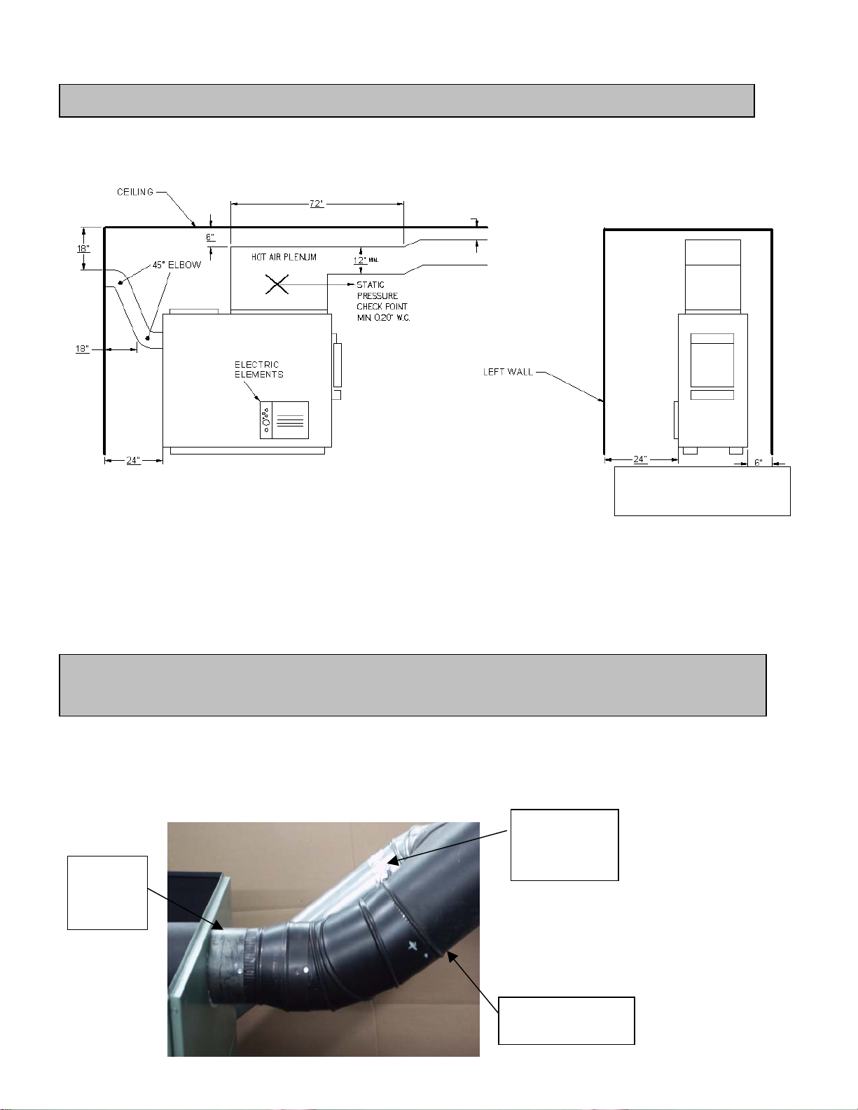
CLEARANCES TO COMBUSTIBLE MATERIALS
N.B. This appliance must be installed in accordance with the instructions on the unit’s certification.
MINIMUM CLEARANCES TO COMBUSTIBLE MATERIALS FOR P SG FURNACES
2”
24” both sides for
PSG5000
N.B. THE AIR RETURN CONDUITS SHOULD BE AT LEAST EQUAL TO THE COLD AIR
PLENUM DIMENSIONS.
PIPE CONNECTOR AND DAMPER
Before proceeding to connection, remove all accessories such as:
scraper, shovel and poker in the evacuation pipe of the furnace.
A 6” diameter chimney listed for use with wood burning heating appliances is recommended for the PSG2000, 7” for
PSG3000-4000 and 8” for the others models. Install the barometric control provided with the furnace. Never install a
manual damper.
WOOD
FLUE
PIPE
7
OIL FLUE
PIPE
(OPTION)
MAIN
COLLECTOR
Page 8

For a proper installation, follow the advices below:
1. All the joints of the evacuation pipe must be secured, using three screws.
Make sure that each screw goes through the inner walls of both connectors (male and female). See
pictures below showing a male-female coupling.
PROPER INSTALLATION UNPROPER INSTALLATION
2. A minimum rise of 1/4 inch per horizontal foot must be respected.
CAUSE RESTRICTION
DAMPER
The barometric control must be adjusted so that the maximum draft measured at the furnace outlet is limited to -0.06
in. w.c. Please note that a draft higher than -0.06 in. H2O could result in an uncontrollable fire. On the other hand,
the minimum draft to be respected is -0.04 in. w.c. in the evacuation pipe on the solid fuel side, no matter what
type of furnace.
COMBUSTION AIR
In the event that the furnace and the chimney are completely cold, it might be necessary before lighting, to provide
fresh air by opening a door or a window for a few minutes.
Take note that a house constructed or renovated in order to be airtight is liable to lack fresh air which is necessary
for a proper combustion and a proper operation of heating units.
In such a case, when starting up the fire, do not operate appliances which evacuate air outside the house such as:
- Range hood
- Air exchanger
- Cloths dryer
- Bathroom fan
- Ventilated central vacuum system
8
Page 9
y
w
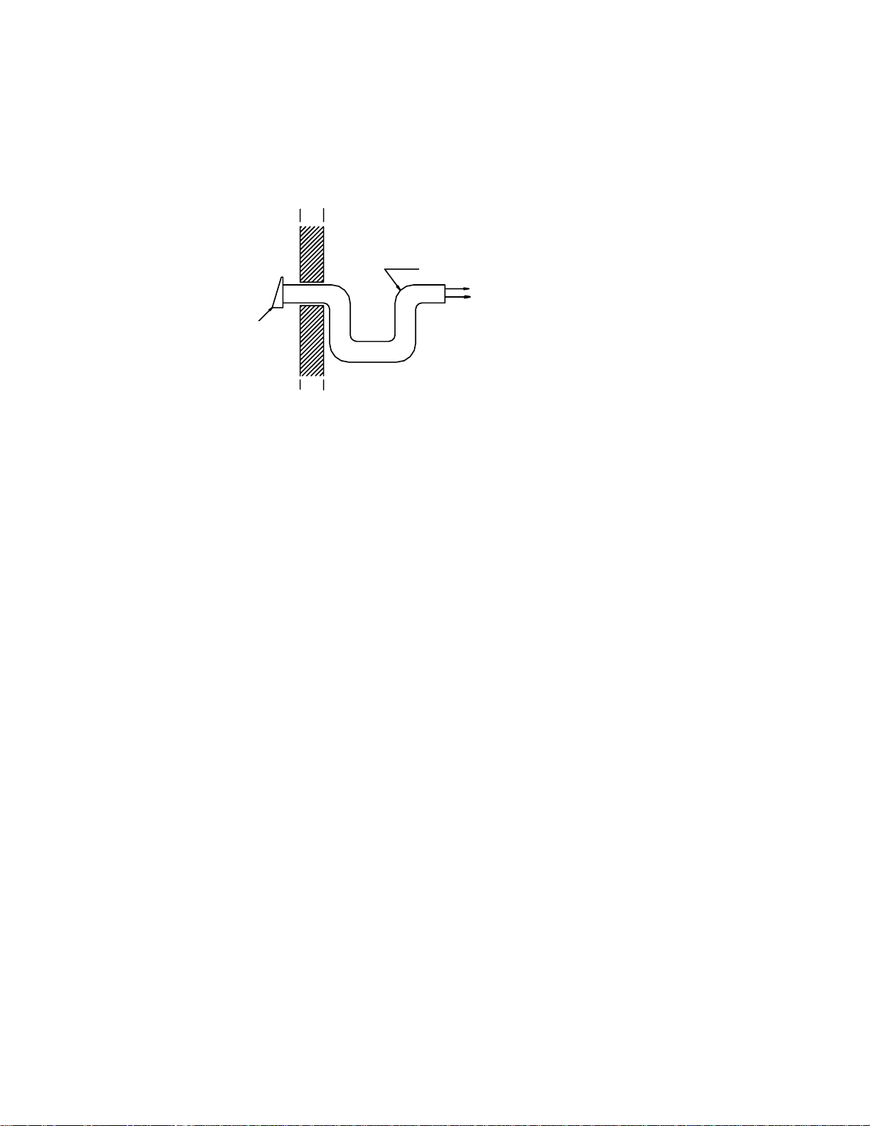
NOTE:
It is recommended to install an outside air inlet of minimum 4” diameter in the room where the heating appliance is
installed (see drawing below). To do so, it is preferable to choose a wall which is not exposed to extreme winds,
according to the conditions surrounding your house.
Insulated conduit full lenght
Free air
entr
Exterior
N
.B. The owner of the furnace is responsible for the room salubrity in case of negative pressure or temporary
negative pressure.
LECTRICAL CONNECTION
E
The following instructions do not supersede the local cod
e.
OOD ONLY
W
Installed limit control on support roper location of the appliance (two holes are predrilled on the edge of
provided on p
the furnace), and connected to the electrical box along with the transformer. Install the servo-motor on the front facade
above the door, on the right side (use pre-drilled holes). The chain that links the air inlet latch to the motor must have a
play of 1/8 in. When there is no call for heat, the air inlet latch must be completely shut and the chain must be affixed
to the servo-motor at “8 o’clock”.
The switch located on the fan limit control activates high speed operation, in either automatic or manual (continuous
operation) modes.
e switch located on the electric unit controls low speed operation, in either ON (continuous operation) or OFF
Th
modes.
ARNING: USE FEEDING WIRES SUITABLE FOR 75OC
W
all
*
Fresh air
intake
W
OOD/ELECTRIC
The limit control is a manual reset thermostatic captor and is located directly inside the electric element (see
WIRING DIAGRAMS). The electric elements must be installed as shown on the diagram. Install the combined limit
control on the support provided, at the determined location. The connections must conform to the diagram.
Install the servo-motor on the front façade above the door, on the right side (use pre-drilled holes). The chain that
links the air inlet latch to the motor must have a play of 1/8 in. When there is no call for heat, the air inlet latch must be
completely shut and the chain must be affixed to the servo-motor at “8 o’clock”.
*
9
Page 10
The switch located on the fan limit control activates the blower at high speed, in either automatic or manual
(continuous operation) modes.
The switch located on the electric unit controls low speed operation, in either ON (continuous operation) or OFF
modes (PSG 3000 or PSG 4000 models only).
WARNING: USE FEEDING WIRES SUITA
* (With all reserves on the minimum combustion air to be increased depending on the type and quality of the
combustible).
BLE FOR 75 C
O
LECTRIC ELEMENT
E
The WOOD / ELECTRIC combin
heating, the other one controls the wood heating. With this system, the electric heating has priority over the wood
heating. When the thermostat activates the electric heating, the air inlet closes down (if opened), the blower starts and
the electric elements are successively activated per block of 5 kW. The system might be equipped with an exterior
thermostat which will allow the last block of elements (5 kW) to start up only when the outside temperature is cold
enough. This will reduce the power of the systems by 5 kW during mild temperature for more comfort.
When the call for electric heating is completed, the wood system will take over if the starting point of the wood
system is superior to the electric system.
So, in normal bi-energy use, you must set the wood system thermostat 2
thermostat.
Take note that this furnace is equipped with a four speed motor. Aside from low speed, three choices are available:
medium-low, medium-high or high.
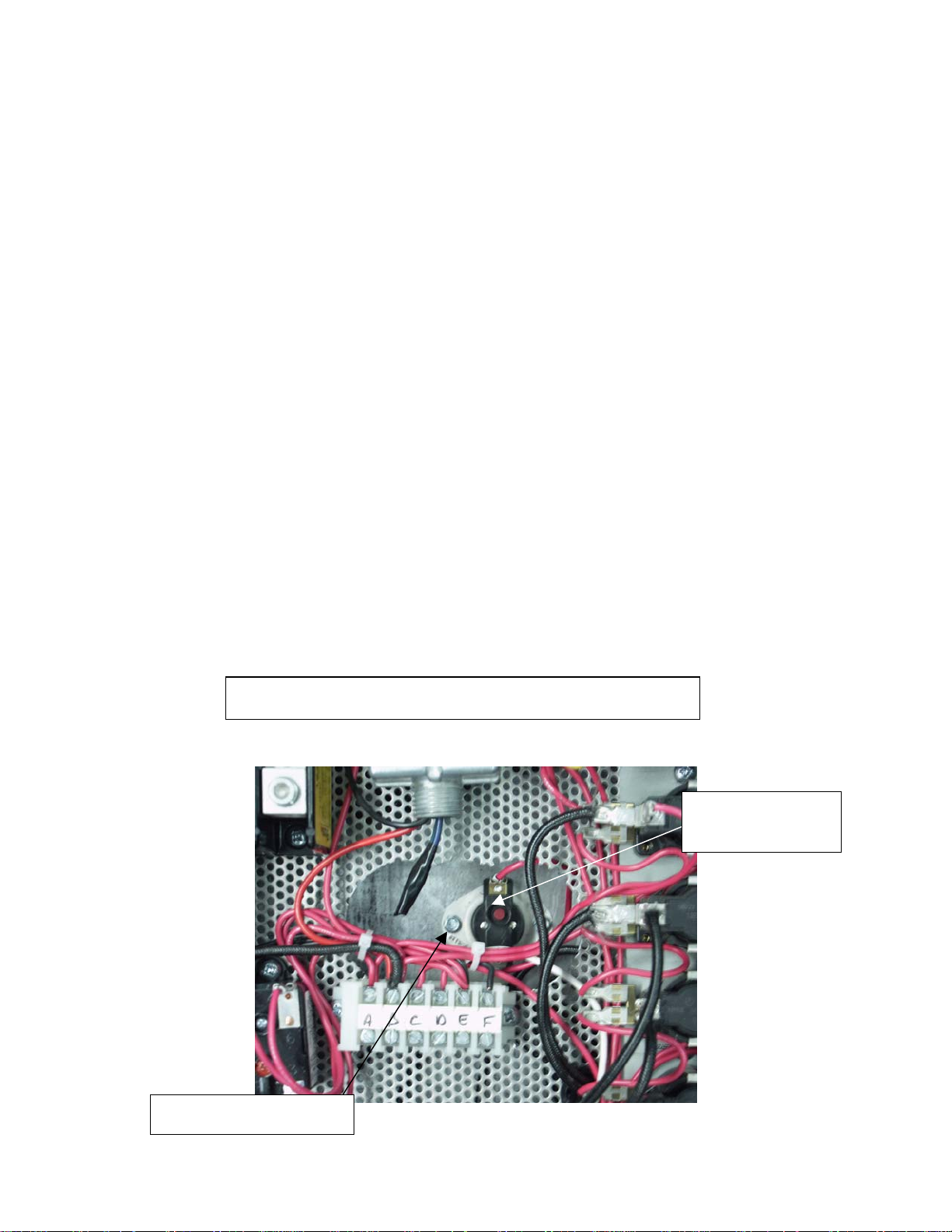
If the temperature of the element exceeds the limit allowed, the thermodisk will disengage the element. For
reactivation, press the red button “manual reset” of the thermodisk L-170 and find out why the temperature limit has
been exceeded (static pressure too high, fan breakage, dirty filter, etc.)
INSIDE VIEW OF THE ELECTRIC ELEMENT
ed model is installed with two thermostats: one thermostat controls the electric
o
to 3o higher than the electric system
Red button
manual rese
t
Thermodisk L-170
10
Page 11

OUTSIDE VIEW OF THE ELECTRIC ELEMENT
THERMOSTAT
The thermostat must be installed on an inside wall in a location where it is not likely to be affected by the draft
coming from an air outlet. It must be installed at a minimum of 55 inches above the floor.
N.B. The combined wood / electric model must be installed with two thermostats at same level.
FAN CONTROL
The fan control setting varies depending on the type of heating installation. The setting “out of service” is preset at
o
F in factory. This setting should provide a proper operation for most installations. The temperature “in service” is
110
pre-set at 150
It is preferable for a prolonged operation of the blower that the setting “out of service” be low enough. But a setting
“out of service” too low will cause a cold air circulation. To modify the setting, turn the button at the desired position on
the temperature scale.
The adjustment of all controls must be performed by a qualified technician. The controls setting and the blower
speed must conform to the recommendations of the “Warm Air Heating and Air Conditioning National Association”. To
obtain a continuous air circulation during summer, push the manual switch of the limit control from the “automatic”
position to the “manual or summer” position.
The switch located below the limit control or on the electric unit, controls the low speed either at the “on” position or
the “off” position. For a better efficiency we recommend to leave the high speed on automatic(wood side fan limit
control).
o
F.
11
Page 12

4. OPERATING INSTRUCTIONS
Control system
On the wood furnaces only, the thermostat controls the air inlet damper. When the thermostat calls for heat, the
damper opens and the fire burns up. When the furnace gets hot enough, the combined limit control activates the
blower motor at the speed selected for wood heating.
The chain that links the air inlet damper to the motor must have a play of 1/8 inch. When there is no call for heat,
the air inlet damper must be completely closed and the chain must be affixed to the servo-motor at “8 o’clock”.
* (With all reserve on the minimum air to be increased depending on the type and quality of the combustible).
LIGHTING:
1. Open the door
Note: In the case that there is a bed of coals in the bottom of the furnace, go to step b) Pre-heating.
2. Place one or two dry kindlings at the front of the furnace.
3. Place newspaper strips on top of the kindlings.
4. Cover the newspaper with more kindlings and small pieces of dry wood.
5. Add newspaper strips, then light the fire a low as possible and leave the door 1/2" (13 mm) opened. If you fail
lighting the fire, you might experience a back draft through the air inlets.
PREHEATING
*
1. Once the kindling is well ignited or the coals revived, put 2 or 3 fire logs in such a way that the flames can interlace
between the logs then close the door. It is important to respect these loading sequences so that the wood will burn
from the front to the back of the furnace.
2. Wait 15 to 20 minutes, then proceed with loading the furnace.
12
Page 13

HEATING
1. When loading the furnace, lower the kindled pieces of wood and place them at the center of the combustion
chamber before adding new logs.
2. Do not overload. Air must circulate freely in the upper part of the furnace in order to obtain an efficient operation of
the appliance. Please note that a small hot fire will produce much less residues than a large smouldering one.
IMPORTANT: DURING THE HEATING PROCESS, REMOVE THE ASHES AND WOOD THAT COULD
OBSTRUCT THE 1/4" (6.4 mm) HOLE LOCATED BELOW THE DOOR INSIDE THE FURNACE.
PROCEDURE TO OPEN THE LOADING DOOR
TO MINIMIZE THE RISK OF A BACK DRAUGHT OPEN THE DOOR 1”
AND WAIT ABOUT 10 SECONDS BEFORE OPENING COMPLETELY.
THE PURPOSE IS TO STABILIZE THE PRESSURE INSIDE THE FURNACE.
EARLY SIGNS OF OVERFIRED FURNACE
1. Roaring fire.
2. Chimney connector is glowing red.
3. Extreme heat coming from the furnace. If this occurs,
completely, and wait until the glow has completely subsided.
DO NOT OPEN THE DOOR
, shut-off the air inlet opening
ALWAYS KEEP THE DOOR AND THE ASH DRAWER CLOSED
(except for lighting and maintenance).
WOOD AS HEATING FUEL
We recommend that you burn dry wood only.
There are two important factors to be considered when choosing a type of wood: the moisture content and the wood
density. Hardwood, such as maple, oak and beech will provide better results because of the high density and minimal
tar produced during combustion. It is highly recommended to use wood that has been dried at least six months.
not use coal as heating fuel in this appliance.
Do
13
Page 14

Whenever a high rate of smoke is noticed in the room, you must:
1. Open doors and windows.
2. Make sure the furnace door is closed as well as the damper (if necessary, lower the thermostat starting point or
undo the chain of the damper and close manually the barometric draft control).
3. When the furnace has cooled down, inspect the chimney to detect obstructions and consult a specialist to
determine the cause.
CARBON MONOXYDE IS A LETHAL GAS (ODOURLESS AND COLOURLESS), WHICH YOU MUST
BEWARE OF.
CHIMNEY FIRES
This might occur when the fire gets extremely hot. Burning cardboard, branches or pieces of wood can ignite the
creosote residue accumulated in the evacuation flue system. The usual signs are:
1. Rumbling
2. The flue gets extremely hot
3. Flames are coming out of the chimney
In case of a chimney fire, first call your local fire department and sprinkle the roof around
the chimney with water.
Make sure that the furnace door is closed as well as the damper (if necessary, lower the thermostat starting point or
release the chain from the damper and CLOSE the barometric draft control manually).
If the fire gets uncontrollable due to an improper use or because the draft is too strong, follow the same procedure
as in a chimney fire except that you will have to OPEN manually the barometric draft control.
LOCAL FIRE DEPARTMENT.
Phone number: ___________________________________
14
Page 15

5. MAINTENANCE
MAINTENANCE OF THE EXCHANGERS
The evacuation pipe and the exchangers should be inspected regularly during the burning season. Using the
scraper, clean the three exchanger pipes.
INSTRUCTIONS
o
Wait until fire is completely out before cleaning.
1
o
Remove the smoke pipe connector from the furnace.
2
o
Inspect the furnace’s heat exchangers (rectangular tubes) through the smoke outlet for creosote accumulation.
3
o
Using the supplied scraper, clean the heat exchangers and the combustion chamber and remove creosote residues.
4
o
Reassemble the smoke pipe connector.
5
CHIMNEY MAINTENANCE
One of the most efficient methods is to sweep the chimney, using a hard brush. Brush up and down. Soot and
creosote residue will come off the inside surface and fall at the bottom of the chimney where it can be removed easily.
The chimney must be checked regularly and if creosote has accumulated, it must be removed. Cleaning on a
monthly basis should be sufficient during the coldest months.
Smoke flue inspection
- The smoke flue should be inspected regularly during the heating season.
- If possible, the smoke flue should be dismantled and cleaned.
- The flue should be inspected to detect any defect.
- If no defect is noticed, put the flue back in place; otherwise, it must be replaced.
- Use only wood as a combustible.
- Seasoned hard wood logs 18” to 22” long are recommended as a combustible.
Regular maintenance is required for safe and efficient operation of a controlled-combustion heating system. Chimney,
gaskets and smoke pipes must remain in good working condition. Change the air filter regularly, with the same type
and same size.
MAINTENANCE OF THE BLOWER MOTOR
The two bearings of the motor must be lubricated once a year using non detergent SAE 20 oil.
DO NOT OVERLUBRICATE
15
Page 16

FILTERS
The furnace must not be operated without the filters. In order to operate a slow combustion heating system
efficiently and safely, you have to ensure a regular maintenance. This means that the chimney, the joints and the flue
must be in good condition. The air filters must be replaced regularly. Use the same size and same type as the original
filters.
DOOR GASKET MAINTENANCE
It is important to maintain the door gasket in good condition. After a while, the gasket might sag; a door adjustment
may be then required.
6. REPLACEMENT PARTS
Your PSG furnace is designed to burn clean and required little maintenance. It’s recommended conduct a visual
inspection at least once a month to uncover that any damage on the unit. Repairs must be done as soon as possible
with the original parts. You can find a complete list of replacement parts on our website at
GASKET
We recommend to replace gasket that seal the door once a year, in order to maintain a good control of the combustion
for maximum efficiency and security. To replace your door gasket, remove the old gasket and glue. Clean the surface
thoroughly, apply glue sold for that particular use, and put the new gasket onto the door. Wait for at least 2 hours
before lighting your furnace.
www.psg-distribution.com.
16
Page 17

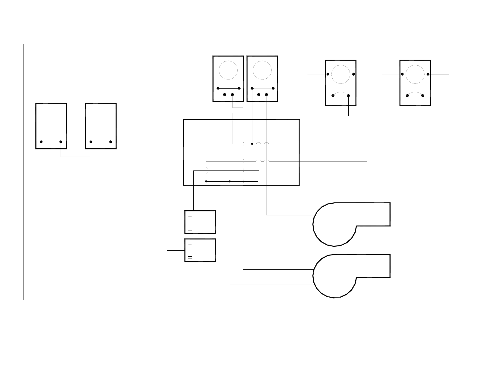
7. ELECTRIC DIAGRAMS FOR UNITS BUILT FROM 2005
WOOD-ONLY FURNACES
FAN LIMIT HONEYWELL L6064(MOTOR (G-10) 4 SPEED AND (G-12) 2 SPEED)
HONEYWELL
L6064
FAN
LINE
LIMIT
LOAD
HIGH LINELOW
ON 150°F
OFF 110°F
LIMIT 250°F
THERMOSTAT SERVO-MOTOR
24 V.A.C.24 V.A.C.
BLUE
RED
BLACK TRANSFO
JUNCTION BOX
BLUE
ON
1
2
SWITCH
3
OFF
BLACK
L1
BLACK
120 V.A.C.
WHITE
L2
BLOWER
4 SPEED
MOTOR
BLACK
WHITE
THERMINAL
BOARD
120 V.A.C.
TRANSFORMER
24 V.A.C.
MOVE THIS WIRE
TO CHANGE
MOTOR SPEED
WHITE
RED
BLACK
HIGH
MED HIGH
MED LOW
LOW
REVISION JUNE 17TH 2005
COMMUN
Page 18

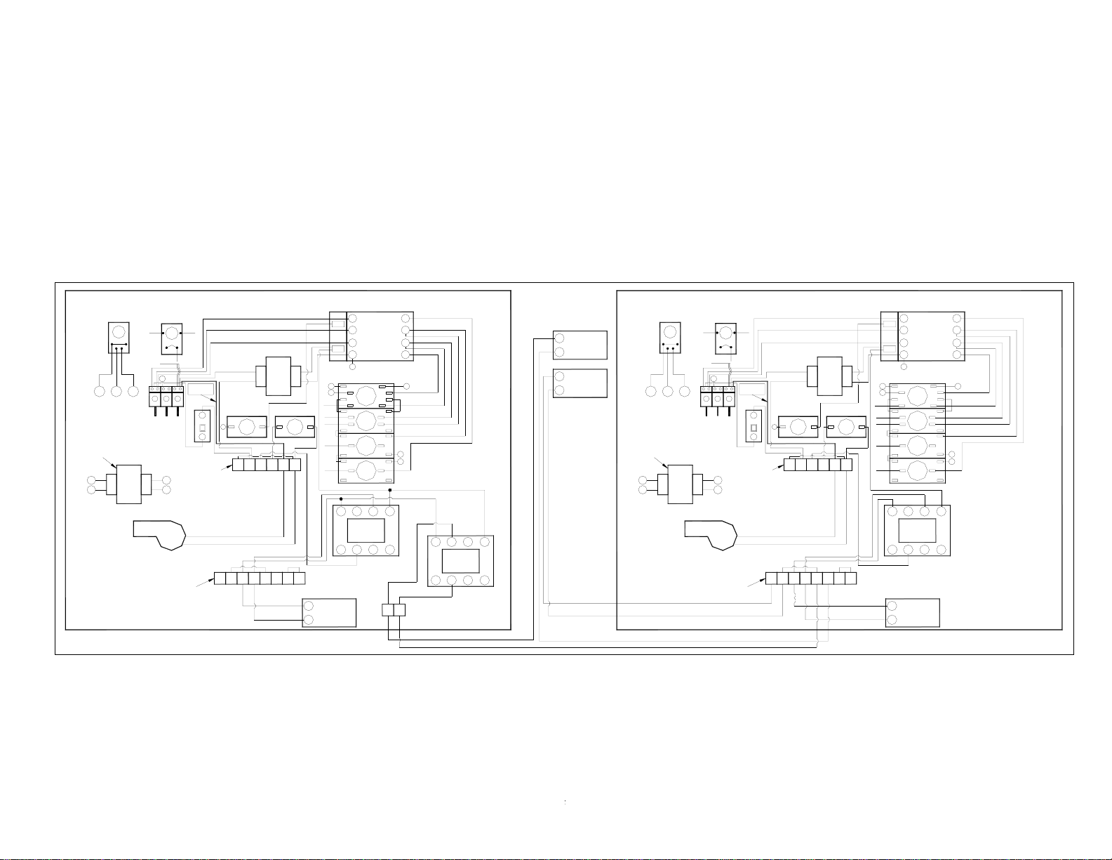
WOOD/ELECTRIC FURNACES
FAN LIMIT HONEYWELL L6064(MOTOR (G-10) 4 SPEED AND (G-12) 2 SPEED)
ELEMENTS
HONEYWELL
L6064
FAN
LINE
B
POWER
BLOCK
RELAY
LOW LINEHIGH
E
1
LIMIT
LOAD
A C
BLACK
BLACK
ON 150°F
OFF 110°F
LIMIT 250°F
TRANSFO
120V
24V
20VA
POWER
BLOCK
E
240V
L1
BREAKER
1
6
BLOWER
4 SPEED
MOTOR
15 KW @ 30KW
S4S3
S2 S5
S6S1
CONNECTORS INDENTIFICATION OF THE SEQUENCER
N L2
20 A
COMMAND
BLOCK
COMMAND
BLOCK
POWER
BLOCK
TERMINAL
HIGH
MED HIGH
MED LOW
LOW
COMMON
REVISION JUNE 16TH 2005
25 KW OR 30 KW ONLY
BLACK
BLACK/RED
L -170 RESET
RELAY
6
MOVE THIS WIRE
TO CHANGE MOTOR SPEED
31 2 45
TRANSFO
240V
24V
40VA
DACB
FAN
1
2
3
FE
768
COIL
24V
COMMAND
4
BLOCK
7
A
SEQUENCER
S3
S1
S1
S2
S3S1
S2
S1
S3
S1
S1
S3
S1
RELAY
POWER
BLOCK
5 KW ELEM.
5 KW ELEM.
5 KW ELEM.
5 KW ELEM.
5 KW ELEM.
12 78
RELAY
3456
COMMAND
BLOCK
CONTACTOR
40 A IND/50A RES
PER POLE
600 V.A.C. MAX.
S4
S5
S5
S4
S4
S4
S5 S6
POWER
B
S6
S6
S6
S6
S6S1
S6
S6
BLOCK
25 KW OR 30 KW ONLY
30 KW ONLY
7
8
BLOCK
COMMAND
1
WOOD
THERMOSTAT
2
3
ELECTRIC
THERMOSTAT
4
5
SERVO
MOTOR
6
Page 19

PSG5000 WOOD-ONLY FURNACES
FAN LIMIT HONEYWELL L6064(MOTOR (G-12) 2 SPEED)
HONEYWELL
L6064
FAN
LIMIT
ON 150°F
OFF 110°F
LIMIT 250°F
HONEYWELL
L6064
FAN LIMIT
THERMOSTAT SERVO-MOTOR
24 V.A.C.24 V.A.C.
JUNCTION BOX
FAN
1
2
3
FAN
1
2
3
WHITE
BLACK
120 V.A.C.
TRANSFORMER
24 V.A.C.
LINE
BLACK
LOW HIGH
RED
LOAD
LINE
BLACK
LINE LOAD
LINELOW HIGH
RED
RED - HIGH SPEED
BLACK - LOW SPEED
WHITE - COMMON
WHITE
L1 - BLACK
120 V.A.C. OR 240 V.A.C.
L2 - WHITE
BLOWER
2 SPEED
MOTOR
REVISION
JUNE 21ST 2005
RED - HIGH SPEED
BLACK - LOW SPEED
WHITE - COMMON
2 SPEED
MOTOR
Page 20

HONEYWELL
L6064
FAN LIMIT
LINE
ON 150°F
ELEMENTS
OFF 110°F
LIMIT 250°F
LOAD
HIGHLOW
LINE
E
240V
ABC
BLOCK
RELAY
24V
BLACK
1
20VA
BLOWER
TRANSFO
120V
BLACK
POWER
E
20 KW @ 30KW
S2
S1
CONNECTORS INDENTIFICATION OF THE SEQUENCER
S4S3
S5
S6
POWER
BLOCK
NL1 L2
COMMAND
1
BLOCK
COMMAND
6
BLOCK
COMMAND
BLOCK
25KW OR 30 KW ONLY
20 A
BREAKER
POWER
BLOCK
RED - HIGH SPEED
WHITE - COMMON
BLACK - LOW SPEED
RELAY
6
L-170 RESET
A B
32 41
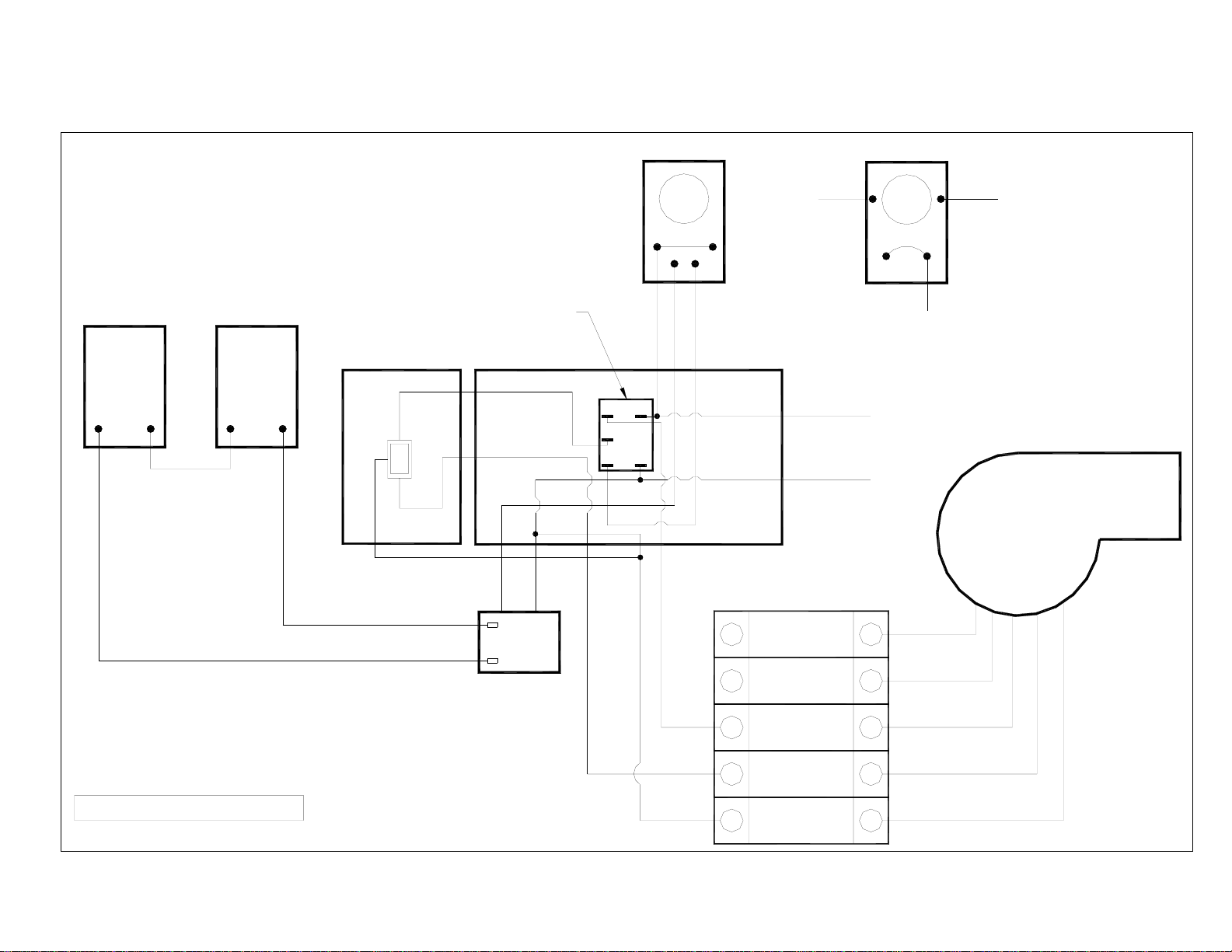
PSG5000 WOOD/ELECTRIC FURNACES
FAN LIMIT HONEYWELL L6064(MOTOR (G-12) 2 SPEED)
HONEYWELL
CONTACTOR
COIL
24V
40 A IND/50A RES
PER POLE
600 V.A.C. MAX.
RELAY
7
POWER
A
BLOCK
5 KW ELEM.
5 KW ELEM.
5 KW ELEM.
5 KW ELEM.
5 KW ELEM.
ELECTRIC
THERMOSTAT
COMMAND
4
BLOCK
SEQUENCER
S3
S1
S1
S2
S3
S1
S1
S2
S1
S3
S1
S1
S3
S1
S5 S6
18
RELAY
#1
3245
S4
S5
S5
S4
S4
S4
S6
S6
S6
S6
S6
S6
S6
7
6
910
POWER
B
BLOCK
7
8
BLOCK
COMMAND
25KW OR 30 KW ONLY
187
2
RELAY
#2
3 456
30 KW ONLY
TRANSFO
240V
24V
40VA
FAN
1
2
3
C
DFE
65
87
3
4 4
1
WOOD
THERMOSTAT
2
SERVO
MOTOR
L6064
POWER
BLOCK
RELAY
20 KW @ 30KW
E
1
HIGHLOW LINE
BLACK
BLACK
ON 150°F
OFF 110°F
LIMITFAN
LIMIT 250°F
ELEMENTS
POWER
E
LOADLINE
BLOCK
240V
L2NL1
ACB
TRANSFO
120V
24V
20VA
BLOWER
COMMAND
1
BLOCK
COMMAND
6
BLOCK
COMMAND
BLOCK
25KW OR 30 KW ONLY
20 A
BREAKER
L -170 RESET
RELAY
6
POWER
BLOCK
RED - HIGH SPEED
WHITE - COMMON
BLACK - LOW SPEED
12 345678
TRANSFO
240V
24V
40VA
B
A FCDE
POWER
BLOCK
5 KW ELEM.
FAN
5 KW ELEM.
1
2
5 KW ELEM.
3
5 KW ELEM.
5 KW ELEM.
RELAY
COIL
24V
7
S1
A
S1
S1
S1
S1
S1
S1
S1
21
3 4
3
CONTACTOR
40 A IND/50A RES
PER POLE
600 V.A.C. MAX.
COMMAND
4
BLOCK
SEQUENCER
S3
S2
S3
S2
S3
S3
RELAY
ELECTRIC
THERMOSTAT
S6
S4
S5
S6
S5
S6
S6
S4
S6
S4
S6
S6
S4
S6
S5
87
56
POWER
B
BLOCK
25KW OR 30 KW ONLY
30 KW ONLY
7
8
BLOCK
COMMAND
20
Page 21

8. ELECTRIC DIAGRAMS FOR UNITS BUILT BEFORE 2005
WOOD ONLY FURNACES PSG 4000 & 4500
BELT-DRIVE G12 MOTOR
WHITE RODGERS
ON 150°F
OFF 110°F
FL
LIMIT 250°F
HONEYWELL
L4064
FL
WHITERED
THERMOSTAT
24 V.A.C.
15 MARS 1990
SERVO-MOTOR
24 V.A.C.
RED
BLACK
WHITE
JUNCTION BOX
ON
NOIR
L1
120 V.A.C.
SWITCH
OFF
BLANC
NOIR
120 V.A.C.
TRANSFORMER
24 V.A.C.
RED - HIGH SPEED
WHITE - COMMON
BLACK - LOW SPEED
2 SPEED
MOTOR
L2
BLOWER
21
Page 22
WOOD ONLY FURNACES PSG 5000
BELT-DRIVE G12 MOTOR
THERMOSTAT
24 V.A.C.
SERVO-MOTOR
24 V.A.C.
JUNCTION BOX
WHITE
BLACK
120 V.A.C.
TRANSFORMER
24 V.A.C.
WHITE RODGERS
FL
RED
BLACK
HONEYWELL
ON 150°F
OFF 110°F
L
BLACK
F
LIMIT 250°F
RED
WHITE
L4064
F
L
NOIR
L1
HONEYWELL
L4064
F
NOIR
L
BLANCROUGEROUGE
120 V.A.C. OR 240 V.A.C.
L2
BLOWER
MOTOR
BLACK
WHITE
1 SPEED
MOTOR
120/240
MARCH 15TH 1990
IMPORTANT: A BREAKER IS MANDATORY FOR 240 VOLT
VERIFY CONNECTIONS OF THE MOTOR 3/4 H.P.
IF CONNECTED ONTO THE RIGHT CIRCUIT(120/240)
FOR 240 VOLT ONLY
240 V.A.C.
TRANSFORMER
24 V.A.C.
22
MOTOR
BLACK
1 SPEED
120/240
MOTOR
WHITE
Page 23

WOOD/ELECTRIC FURNACES PSG 4000 & 4500
BELT-DRIVE G12 MOTOR
POWER
BLOCK
RELAY
LOW SPEED
SWITCH
BLACK
BLUE
BLACK
E
BLACK
1
WHITE RODGERS
L
RED
WHITE
BLACK
BLACK
WHITE
TRANSFO
120V
24V
20VA
F
ON 150°F
OFF 110°F
LIMIT 250°F
RED
DCBA
BLOWER
RED
ELEMENTS
E
240V
1
2 SPEED
MOTOR
HONEYWELL
L4064
POWER
BLOCK
L2NL1
COMMAND
BLOCK
COMMAND
6
BLOCK
LF
WHITE
BLACK
110 VOLT
MOTOR 3/4 H.P.
FOR 240 V
20 A
BREAKER
POWER
BLOCK
HIGH SPEED - RED
COMMON - WHITE
LOW SPEED - BLACK
RELAY
6
TRANSFO
240V
24V
40VA
CONTACTOR
COIL
24V
RELAY
7
POWER
BLOCK
A
5 KW ELEM.
F- 110L- 160
FEDCBA
5 KW ELEM.
5 KW ELEM.
5 KW ELEM.
5 KW ELEM.
40 A IND/50A RES
PER PÔLE
600 V.A.C. MAX.
COMMAND
4
BLOCK
SEQUENCER
POWER
B
BLOCK
7
8
BLOCK
COMMAND
1
25 KW ONLY
WOOD
THERMOSTAT
2
3
ELECTRIC
THERMOSTAT
7812
RELAY
4
5
SERVO
MOTOR
3456
6
15 KW @ 30KW
COMMAND
BLOCK
8712 3456
23
Page 24
WOOD/ELECTRIC FURNACES PSG 5000 40KW @ 60KW
BELT-DRIVE G12 MOTOR
WHITE RODGERS
F
L
BLACK
RED
BLACK
WHITE
C AB
IMPORTANT:
IT IS MANDATORY TO CHANGE THE
TRANSFORMER 120-24 FOR A 240-24
IF YOU USED 3/4 H.P. MOTOR ON 240 V
TRANSFO
BLACK
POWER
BLOCK
RELAY
120V
E
24V
BLACK
1
20VA
20 KW @ 30KW
ON 150°F
OFF 110°F
LIMIT 250°F
BLOWER
RED
HONEYWELL
L4064
F L
ELEMENTS
POWER
E
BLOCK
240V
NL1
COMMAND
1
BLOCK
COMMAND
6
BLOCK
COMMAND
BLOCK
F
ON 150°F
OFF 110°F
LIMIT 250°F
AC
BLOWER
RED
ELEMENTS
E
240V
HONEYWELL
L4064
F
WHITE
POWER
BLOCK
L2NL1
COMMAND
1
BLOCK
COMMAND
6
BLOCK
COMMAND
BLOCK
L
BLACK FROM
TRANSFO
110 VOLT LINE
3/4 H.P. MOTOR
240 V
BREAKER
WHITE
BLACK
20 A
POWER
BLOCK
TRANSFO
240V
24V
40VA
L -160
RELAY
6
BA
32
14
CONTACTOR
COIL
24V
40 A IND/50A RES
PER POLE
600 V.A.C. MAX.
COMMAND
4
BLOCK
SEQUENCER
RELAY
7
POWER
A
BLOCK
5 KW ELEM.
F -110
5 KW ELEM.
5 KW ELEM.
5 KW ELEM.
EDC
F
5 KW ELEM.
2
1
POWER
B
BLOCK
7
8
BLOCK
COMMAND
78
RELAY
65
43
8765
3
ELECTRIC
THERMOSTAT
4
WHITE RODGERS
L
BLACK
RED
BLACK
WHITE
B
IMPORTANT:
IT IS MANDATORY TO CHANGE THE
TRANSFORMER 120-24 FOR A 240-24
IF YOU USED 3/4 H.P. MOTOR ON 240 V
TRANSFO
120V
BLACK
POWER
E
BLOCK
RELAY
24V
BLACK
1
20VA
20 KW @ 30KW
RELAY
CONTACTOR
COIL
24V
40 A IND/50A RES
PER PÔLE
600 V.A.C. MAX.
BLOC
4
COMMANDE
SEQUENCER
7
A
2
POWER
B
BLOCK
7
8
BLOCK
COMMAND
781
1
WOOD
THERMOSTAT
2
SERVO
MOTOR
RELAY
3
654
78
RELAY
651243
109
BLACK FROM
TRANSFO
WHITE
110 VOLT LINE
3/4 H.P. MOTOR
240 V
L2
20 A
RELAY
6
BREAKER
POWER
BLOCK
WHITE
BLACK
1 42 3 5
L- 160
TRANSFO
240V
24V
40VA
DBCA
POWER
BLOCK
5 KW ELEM.
F- 110
5 KW ELEM.
5 KW ELEM.
5 KW ELEM.
E F
5 KW ELEM.
7 8
6
3
ELECTRIC
THERMOSTAT
4
Page 25
WOOD ONLY FURNACES PSG 2000-3000-4000
DIRECT-DRIVE G10 MOTOR
WHITE RODGERS
FL
ON 150°F
OFF 110°F
LIMIT 250°F
RED
HONEYWELL
L4064
LF
BLACK FROM
TRANSFO
THERMOSTAT
24 V.A.C.
SERVO-MOTOR
24 V.A.C.
RELAY
BLACK
BLACK TRANSFO
RED
JUNCTION BOX
RED
ON
1
3
2
OFF
SWITCH
BLACK
4
2
5
31
L1
120 V.A.C.
L2
BLACK
BLOWER
4 SPEED
MOTOR
TERMINAL
WHITE
BLACK
BOARD
120 V.A.C.
TRANSFORMER
24 V.A.C.
WHITE
BLACK
RED
HIGH
MED HIGH
MED LOW
REVISION MAY 20TH 1994
LOW
COMMUN
25
Page 26

WHITE RODGERS
LF
BLACK
WHITE
RED
BLACK
B
C
POWER
BLOCK
RELAY
BLACK
E
BLACK
1
A
ON 150°F
OFF 110°F
LIMIT 250°F
TRANSFO
120V
24V
20VA
RED
WOOD/ELECTRIC FURNACES PSG 2000-3000-4000
DIRECT-DRIVE G10 MOTOR
HONEYWELL
L4064
F
L1
WHITE
ELEMENTS
POWER
E
BLOCK
240V
1
6
L
BLACK TO
TRANSFOMER
L2N
COMMAND
BLOCK
COMMAND
BLOCK
20 A
BREAKER
POWER
BLOCK
L -170 RESET
RELAY
6
COIL
24V
TRANSFO
240V
24V
40VA
FAN
5
FAN
RELAY
A
CB D
E
F
RELAY
7
A
POWER
BLOCK
ELEM. 5 KW
ELEM. 5 KW
ELEM. 5 KW
ELEM. 5 KW
ELEM. 5 KW
4
SEQUENCER
CONTACTOR
40 A IND/50A RES
PER POLE
600 V.A.C. MAX.
COMMAND
BLOCK
POWER
B
BLOCK
25 KW ONLY
30 KW ONLY
7
8
BLOCK
COMMAND
BLOWER
4 SPEED
MOTOR
15 KW @ 30KW
TERMINAL
BOARD
HIGH
MED HIGH
MED LOW
LOW
COMMUN
COMMAND
BLOCK
FAN RELAY
POWER
BLOCK
D
TO CHANGE MOTOR SPEED
2
5
3
E
POWER
BLOCK
MOVE THIS WIRE
4
1
POWER
BLOCK
1 2 4365
POWER
BLOCK
A
B
2 1
3 456
78
87
RELAY
1
WOOD
THERMOSTAT
2
3
ELECTRIC
THERMOSTAT
4
5
SERVO
MOTOR
6
Page 27

9. TECHNICAL SPECIFICATIONS
A
B
C
D
E
F
G
PIPES
WEIGHT
2000 3000 4000 4500 5000
45 ¼" 47" 50" 52 ½" 54 ½"
23 ½" 25 ½" 29 ½" 33 ½" 54"
45 ½" 47 ¼" 48" 48" 56 ¾"
15 ⅞" 15 ⅞" 19" 19" 19 ¾"
26 ⅜" 28" 28" 30" 31 ½"
22 ½" 24 ½" 28 ½" 32 ½" 51 ⅛"
40 ½" 41 ¼" 42" 42" 49 ½"
7" 8" 8" 8" 8"
445 540 600 660 1200
GENERAL TECHNICAL DATA
MODEL BELT DRIVE DIRECT DRIVE
FAN MOTOR SPEED
H
2000 N/A G-10 1/3 4 950 68 70000 0,2 0,4 11 x 20
3000 N/A G-10 1/3 4 1300 78 110000 0,2 0,6 12 x 24
4000 N/A G-10 1/3 4 1300 128 180000 0,2 0,6 12 x 24
4000 G-12 3/4 2 N/A 1800 93 180000 0,2 0,8 12 x 24
4500 G-12 3/4 2 N/A 1800 121 235000 0,2 0,8 12 x 24
5000 G-12 3/4 2 N/A 3600 125 350000 0,2 1,45 20 x 24
(
*
TECHNICAL DATA – ELECTRIC MODE
MODEL OUTPUT
(C.F.M.)
15 KW 950
1300
1800
18 KW 950
1300
1800
20 KW 950
1300
1800
25 KW 950
1300
1800
30 KW 1300
1800
WOOD 15 120
TEMP. VAR.
O
(
F)
50
36
26
60
44
32
67
49
35
83
61
44
73
53
FAN MOTOR SPEED OUTPUT
BTU/HR AMPERES
TOTAL
51195 75 100 4 120/240 3 – 5 KW
61434 87 100 4 120/240 2 – 5 KW, 2 – 4 KW
68260 95 115 3 120/240 4 – 5 KW
85325 115 140 2 120/240 5 – 5 KW
102390 140 170 1 120/240 6 – 5 KW
BREAKER
REQUIRED
(C.F.M.)
FEEDER
GAUGE
TEMP
VAR.
O
F) (WOOD) ( "WATER)
SINGLE PHASE
BTU/
HR
VOLTAGE
STATIC
PRESSURE
2
ELEMENTS
FILTER
(2)
O
QTY
27
Page 28

10. SELECTION CRITERIA (COMBINED WOOD/ELECTRIC FURNACE)
RESIDENTIAL AREA
House including: basement, first floor and second floor (half)
Floor area * New house Existing house
1100 square feet or less PSG 2000 – 15 PSG 2000 – 18 or 20
1100 to 1450 square feet PSG 3000 – 18 PSG 3000 – 20 or 25
1400 to 2000 square feet PSG 4000 – 20 PSG 4000 – 25 or 30
2000 to 3000 square feet PSG 4500 – 25 PSG 4500 – 30
COMMERCIAL AREA
Building including: Walls 14 to 16 feet high
Garage doors, no basement
Floor area
2500 to 3800 square feet PSG 4500 Wood
4000 to 10000 square feet PSG 5000 – 40 or 60
* Consider main floor only.
28
Page 29

11. TROUBLESHOOTING
PROBLEM
1. Sudden drop in heating
performance follows adequate
heating from first loadings.
2. Insufficient heat from first loadings,
low draft
3. Poor heating in the rooms while
hot air plenum and furnace are hot.
4. Furnace burns too much wood.
5. Fan starts too late.
6. Creosote accumulation, very
average performance.
7. Hot air plenum remains barely
warm while furnace in full operation.
CAUSES
Ash accumulation at lower intake
blocks combustion air intake and
causes deposits in heat exchanger
and flue pipes.
Wrong setting of draft regulator
(opening too large).
Restriction in chimney flue (excessive
length of chimney connector, rightangled elbows).
Inadequate duct installation.
Insufficient static pressure.
Unbalanced system (too many hot air
outlets for too few cold air intakes).
The thermostats controlling the air
combustion damper is located too
close to cold air and demands heat
continuously.
Wrong setting of air intake register.
Poor building insulation.
Ash drawer left open.
Furnace too small for heating needs.
Unbalanced ventilation system,
insufficient heat near thermostat.
Fan starting temperature is too high.
Cold air return is too cold.
Inappropriate location of fan limit
control in hot air plenum.
Damp wood.
Insufficient draft.
Clogged chimney.
Damp wood.
Too much cold air return in relation to
hot air ducts.
Unbalanced ventilation system.
SOLUTIONS
Clear air intake of any ash
accumulation.
Clean heat exchanger and flue pipes.
Set draft regulator (reduce opening).
Reduce distance between furnace
and chimney and eliminate 90
elbows.
Maximum length: 10 feet.
Tight-angle elbows: maximum 3.
Reposition ducts.
Relocate thermostat.
Adjust chain between damper motor
and combustion air damper.
Balance the ventilation system as to
increase the flow air in room where
thermostat is located.
Lower starting temperature (the fan
limit control is normally set at 150
under certain conditions, this limit
should be reduced.
Reduce the cold air intake.
Relocate fan limit control within the
hot air plenum.
Use dry wood.
Adjust draft regulator.
Clean chimney, chimney connector
and furnace heat exchangers.
Use dry wood.
Redistribute ventilation system.
o
o
F);
IMPORTANT NOTE
WE STRONGLY RECOMMEND CONSULTING A HEATING SYSTEM SPECIALIST
FOR THE INSTALLATION OF A CENTRAL HEATING VENTILATION SYSTEM.
N.B.: STOVE BUILDER INTERNATIONAL INC. IS NOT LIABLE FOR ANY FAULTY INSTALLATION WHICH RENDERS THIS
UNIT INOPERATIVE
29
Page 30

12. DUCTS AND REGISTER MEASUREMENTS
(sample calculations)
SIMPLIFIED METHOD
DISTRIBUTION SYSTEM
Ducts size (heat)
4 inch outlet reduce by 1”
5 inch outlet reduce by 2” Always by 8” thick
6 inch outlet reduce by 3”
N.B.: The main duct must be reduced every 2
outlets.
Ducts specifications (heat)
Dimensions Length Elbow Average equivalence
o
4” 10’ 1 x 90
5” 10’ 1 x 90
6” 10’ 1 x 90
DAMPER
For a 4” warm air outlet: 2” x 10” damper
For a 5” warm air outlet: 2” x 12” damper or 4” x 10”
For a 6” warm air outlet: 2” x 14” damper or 4” x 12”
Max 4,000 Btu
o
o
Max 6,000 Btu
Max 7,000 Btu
HOUSE DIMENSIONS
Example: 28 x 40 bungalow: 1,120 sq. ft.
28 x 40 x 8: 8,960 cu. ft. x 1.8 Ch. air/hr: 16,128 Btu
Exposed walls:
40 + 40 + 28 + 28: 136 x 8: 1,088 cu. ft. x 22: 23,936 Btu
Number of windows:
12 of 3 x 4: 144 x 60: 8,640 Btu
Number of doors:
2 x 3 x 7: 42 x 100:
Non-insulated basement: 25%
Insulated basement: 15%
or 54 Btu per sq. ft.
FOR ELECTRIC ELEMENTS 80%:48,672 Btu or 14,28 kW
TO BE ADDED: House 1 1/2 floor = 25%
House 2 floors = 40%
BEDROOM (for example: 12 x 12)
12 x 12 x 8: 1,152 cu. ft. x 1.8 Ch. air/hr: 2,074 Btu
WARM AIR SYSTEM INSTALLATION
4,200 Btu
52,904 Btu
7,906 Btu
60,840 Btu
Exposed walls:
12 + 12 x 8: 192 x 22: 4,224 Btu
Windows:
3 x 4 x 60
7,018 Btu
720 Btu
30
Page 31

1700, rue Léon-Harmel, Québec (Québec) G1N 4R9
tel. : (418) 527-3060 fax : (418) 527-4311
e-mail : tech@sbi-international.com web site : www.psg-distribution.com
LIMITED LIFETIME WARRANTY
The PSG warranty extends only to the original consumer purchaser and is not transferable. This warranty covers brand new
products only, which have not been altered, modified nor repaired since shipment from factory. Proof of purchase (dated bill of
sale), model name and serial number must be supplied when making any warranty claim to your PSG dealer
This warranty applies to normal use only. Damages caused by misuse, abuse, improper installation, lack of maintenance, over firing,
negligence or accident during transportation are not covered by this warranty.
This warranty does not cover any scratch or discoloration caused by over firing, abrasives or chemical cleaners. Any defect or
damage caused by the use of unauthorized parts or others than original parts void this warranty.
An authorized qualified technician must perform the installation in accordance with the Instructions supplied with this product and
all local and national building codes. Any service call related to an improper installation is not covered by this warranty.
Returned products are to be shipped prepaid to PSG for investigation. If a product is found to be defective, PSG will repair or replace
such defect and reasonable transportation fees will be refund. Repair work covered by the warranty, executed at the purchaser
domicile by an authorized qualified technician requires the prior approval of PSG. Labour cost and repair work to the account of PSG
are based on predetermined rate schedule and must not exceed the wholesale price of the replacement part.
PSG at its discretion may decide to repair or replace any part or unit after inspection and investigation of the defect. PSG may, at its
discretion, fully discharge all obligations with respect to this warranty by refunding the wholesale price of any warranted but
defective parts
PSG shall in no event be responsible for any special, indirect, consequential damages of any nature, which are in excess of the
original purchase price of the product.
DESCRIPTION
Combustion chamber (weldings only) Lifetime 5 years
Perforation caused by rust 5 years n/a
Stainless steel baffle 5 years 1 year
Carbon steel baffle 2 years 1 year
Handle assembly 5 years n/a
Ash drawer Lifetime 1 year
Cast iron parts 5 years 1 year
Ceramic glass (thermal breakage only) 1 year n/a
Paint, refractory bricks, gasket, blower, thermal switch (thermodisc) and
rheostat
Plating 1 year n/a
Shall your unit or a components be defective, contact immediately your PSG dealer. Prior to your call make sure you have the
following information necessary to your warranty claim treatment:
• You name, address and telephone number; • Serial number and model name as indicated on the
• Bill of sale, dealer’s name;
Before shipping your unit or defective component to our plant, you must obtain from your PSG dealer an
Authorization Number. Any merchandise shipped to our plant without authorization will be refused
automatically and returned to sender.
nameplate fixed to the back of your unit;
• Nature of the defect and any relevant information.
WARRANTY APPLICATION
PARTS LABOUR
1 year n/a
31
 Loading...