

Page 1
F61-2XXX
WHITE-RODGERS
Operator: Save these instructions for future use!
FAILURE TO READ AND FOLLOW ALL INSTRUCTIONS CAREFULLY
BEFORE INSTALLING OR OPERATING THIS CONTROL COULD CAUSE
PERSONAL INJURY AND/OR PROPERTY DAMAGE.
This adaptor plate assembly is designed for mounting
heating only, cooling only, or heating/cooling thermostats, such as the 1F30, 1F56, etc. This adaptor plate
assembly can be used to mount either horizontal or
CAUTION
!
To prevent electrical shock and/or equipment damage, disconnect electrical power
at main fuse or circuit breaker until installation is complete.
Adaptor Plate Assembly
INST ALLA TION INSTRUCTIONS
DESCRIPTION
vertical thermostats to the wall or to a junction box. The
wall cover plate covers the junction box, wall damage, or
old thermostat markings. (Note: Some adaptor plate assembly kits may not contain the metal adaptor plate.)
PRECAUTIONS
NOTE
This instruction sheet is not intended as a wiring guide.
Refer to the thermostat installation instructions to ensure
proper wiring.
NOTE
Do not install the wall mounting plate and subbase at the
same time. The thermostat will not operate properly if
both the wall mounting plate and the subbase are installed.
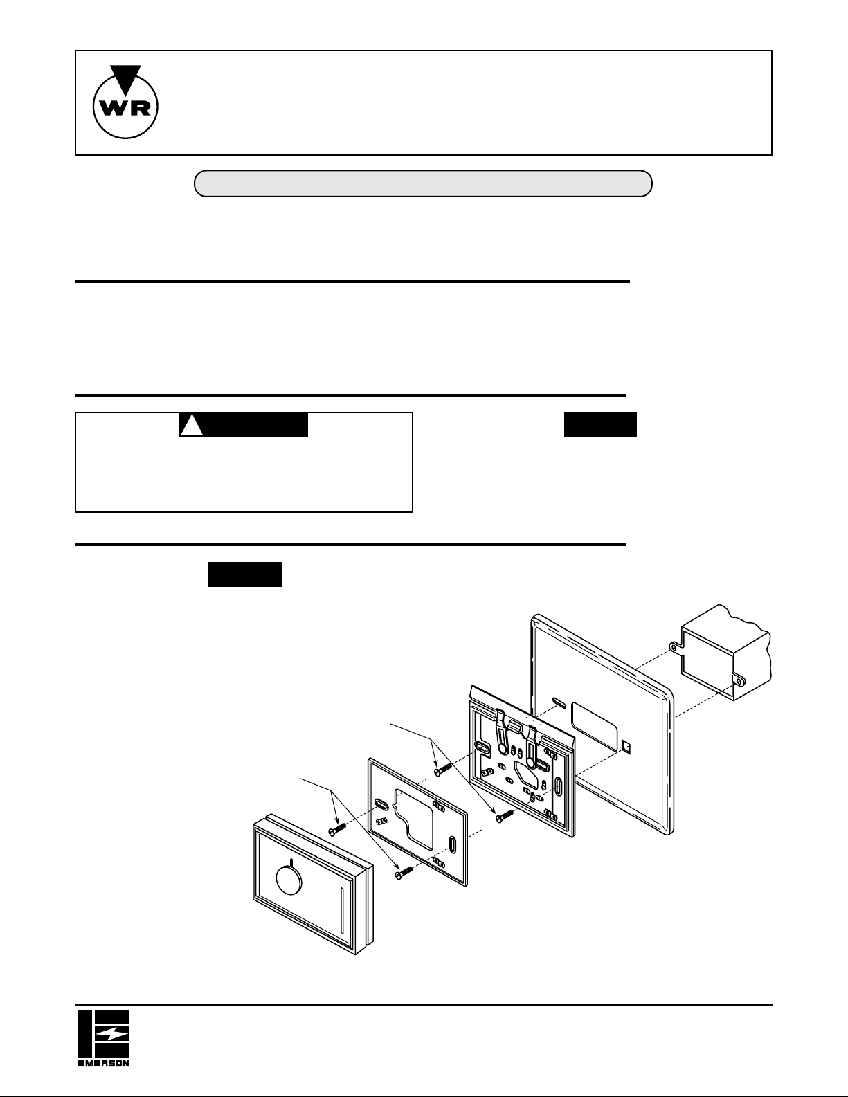
For horizontal thermostats, mount as shown in the
following illustrations. For vertical thermostats, rotate all parts 90° clockwise.
6-32 X 3⁄4” flat-head
machine screws
6-32 X 3⁄4” flat-head
machine screws
Wall Mounting
Plate*
AUTO ON
FAN
INSTALLATION
SYSTEM
COOL HEAT
OFF
Thermostat
Subbase*
*Do not use both subbase and wall
mounting plate – see note, above.
Wall Cover Plate
Junction Box
Thermostat
Figure 1. Mounting thermostat to horizontal junction box
WHITE-RODGERS DIVISION
EMERSON ELECTRIC CO.
9797 REAVIS ROAD
ST. LOUIS, MISSOURI 63123-5398
Printed in U.S.A.
PART NO. 37-5535A
9524
Page 2
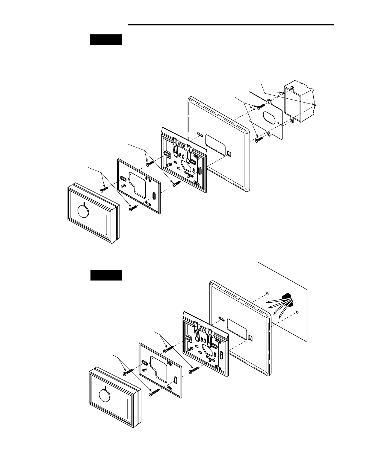
INST ALLATION (cont’d)
NOTE
Do not install the wall mounting plate and subbase at the
same time. The thermostat will not operate properly if both
the wall mounting plate and the subbase are installed.
AUTO ON
6-32 X 3⁄4” flat-head
machine screws
6-32 X 3⁄4” flat-head
machine screws
Locate and drill two
clearance holes in wall
6-32 X 3⁄4” flat-head
machine screws
Junction Box
FAN
SYSTEM
COOL HEAT
OFF
Adaptor Plate
Wall Mounting
Plate*
Thermostat
Figure 2. Mounting thermostat to vertical junction box
NOTE
When installing the wall cover plate and thermostat directly to the wall, use the pointed screws supplied with the
thermostat.
No. 6 X 1” pan-head screws
(supplied with thermostat)
No. 6 X 1” pan-head screws
(supplied with thermostat)
Thermostat
Subbase*
*Do not use both subbase and wall
mounting plate – see note, above.
FAN
AUTO ON
COOL HEAT
SYSTEM
OFF
Wall Cover Plate
Wall
Thermostat
Thermostat
Subbase*
*Do not use both subbase and wall
Wall Mounting
mounting plate – see note, above.
Plate*
Figure 3. Mounting thermostat to wall
Wall Cover Plate
 Loading...