

Page 1
F145-1328/F145-1378F145-1328/F145-1378
F145-1328/F145-1378
F145-1328/F145-1378F145-1328/F145-1378
Indoor Remote Sensor/Outdoor Remote Sensor
INSTALLATION INSTRUCTIONSINSTALLATION INSTRUCTIONS
INSTALLATION INSTRUCTIONS
INSTALLATION INSTRUCTIONSINSTALLATION INSTRUCTIONS
Operator: Save these instructions for future use!Operator: Save these instructions for future use!
Operator: Save these instructions for future use!
Operator: Save these instructions for future use!Operator: Save these instructions for future use!
FAILURE TO READ AND FOLLOW ALL INSTRUCTIONS CAREFULLY BEFOREFAILURE TO READ AND FOLLOW ALL INSTRUCTIONS CAREFULLY BEFORE
FAILURE TO READ AND FOLLOW ALL INSTRUCTIONS CAREFULLY BEFORE
FAILURE TO READ AND FOLLOW ALL INSTRUCTIONS CAREFULLY BEFOREFAILURE TO READ AND FOLLOW ALL INSTRUCTIONS CAREFULLY BEFORE
INSTALLING OR OPERATING THIS CONTROL COULD CAUSE PERSONALINSTALLING OR OPERATING THIS CONTROL COULD CAUSE PERSONAL
INSTALLING OR OPERATING THIS CONTROL COULD CAUSE PERSONAL
INSTALLING OR OPERATING THIS CONTROL COULD CAUSE PERSONALINSTALLING OR OPERATING THIS CONTROL COULD CAUSE PERSONAL
INJURY AND/OR PROPERTY DAMAGE.INJURY AND/OR PROPERTY DAMAGE.
INJURY AND/OR PROPERTY DAMAGE.
INJURY AND/OR PROPERTY DAMAGE.INJURY AND/OR PROPERTY DAMAGE.
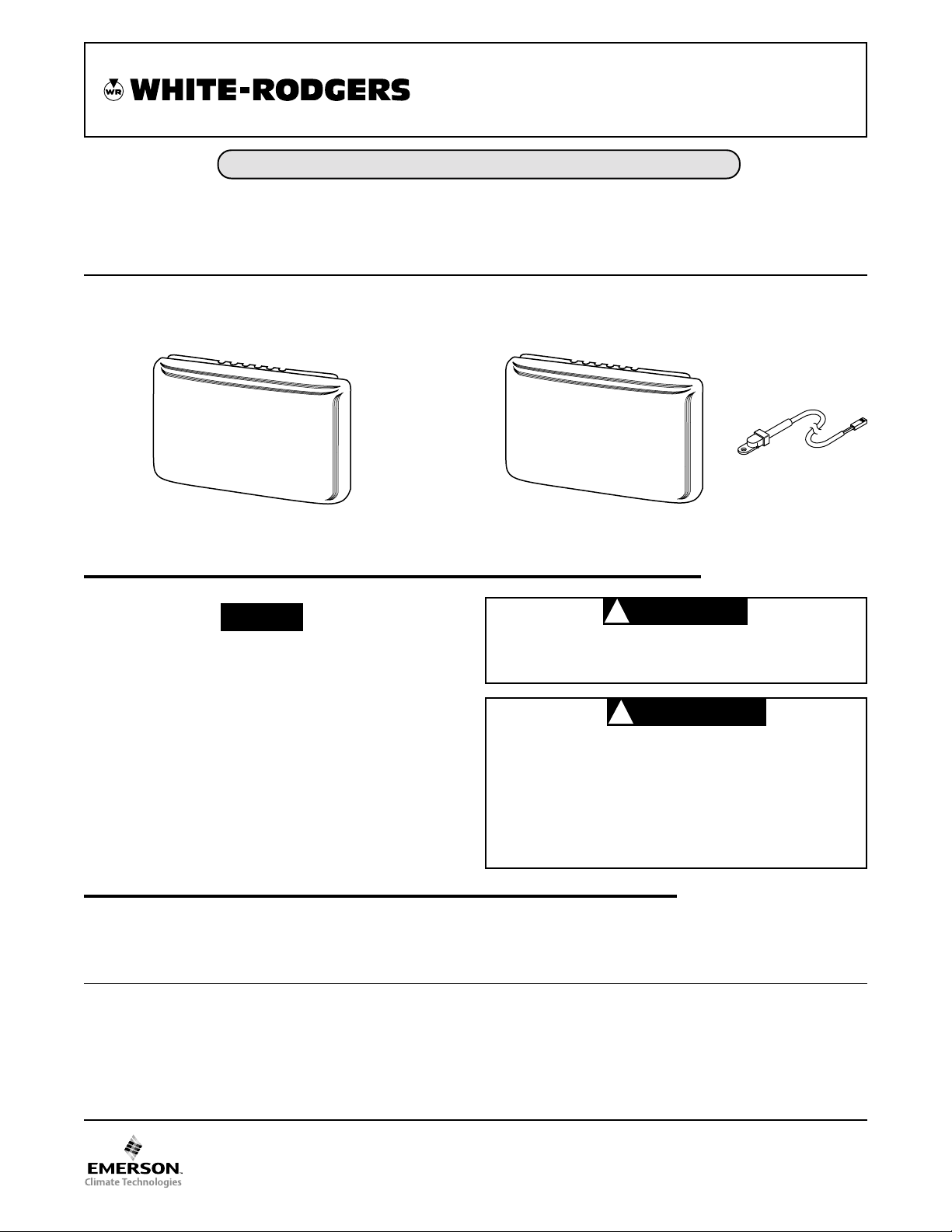
INDOOR REMOTE SENSORINDOOR REMOTE SENSOR
INDOOR REMOTE SENSOR
INDOOR REMOTE SENSORINDOOR REMOTE SENSOR
NOTE
If in doubt about whether your wiring is millivolt, line, or low
voltage, have it inspected by a qualified heating and air
conditioning contractor or electrician.
Do not exceed the specification ratings.
All wiring must conform to local and national electrical codes
and ordinances.
This control is a precision instrument, and should be handled
carefully. Rough handling or distorting components could cause
the control to malfunction.
The remote sensors cannot be used with systems where power
interruptions are part of normal system operation.
OUTDOOR REMOTE SENSOROUTDOOR REMOTE SENSOR
OUTDOOR REMOTE SENSOR
OUTDOOR REMOTE SENSOROUTDOOR REMOTE SENSOR
Outdoor ProbeOutdoor Probe
Outdoor Probe
Outdoor ProbeOutdoor Probe
Interior Mounting BaseInterior Mounting Base
Interior Mounting Base
Interior Mounting BaseInterior Mounting Base
PRECAUTIONSPRECAUTIONS
PRECAUTIONS
PRECAUTIONSPRECAUTIONS
CAUTION
!
To prevent electrical shock and/or equipment dam-To prevent electrical shock and/or equipment dam-
To prevent electrical shock and/or equipment dam-
To prevent electrical shock and/or equipment dam-To prevent electrical shock and/or equipment damage, disconnect electric power to system at main fuseage, disconnect electric power to system at main fuse
age, disconnect electric power to system at main fuse
age, disconnect electric power to system at main fuseage, disconnect electric power to system at main fuse
or circuit breaker box until installation is complete.or circuit breaker box until installation is complete.
or circuit breaker box until installation is complete.
or circuit breaker box until installation is complete.or circuit breaker box until installation is complete.
WARNING
!
Do not use on circuits exceeding specified voltage.Do not use on circuits exceeding specified voltage.
Do not use on circuits exceeding specified voltage.
Do not use on circuits exceeding specified voltage.Do not use on circuits exceeding specified voltage.
Higher voltage will damage control and could causeHigher voltage will damage control and could cause
Higher voltage will damage control and could cause
Higher voltage will damage control and could causeHigher voltage will damage control and could cause
shock or fire hazard.shock or fire hazard.
shock or fire hazard.
shock or fire hazard.shock or fire hazard.
Do not short out terminals on gas valve or primaryDo not short out terminals on gas valve or primary
Do not short out terminals on gas valve or primary
Do not short out terminals on gas valve or primaryDo not short out terminals on gas valve or primary
control to test. Short or incorrect wiring will damagecontrol to test. Short or incorrect wiring will damage
control to test. Short or incorrect wiring will damage
control to test. Short or incorrect wiring will damagecontrol to test. Short or incorrect wiring will damage
thermostat and could cause personal injury and/orthermostat and could cause personal injury and/or
thermostat and could cause personal injury and/or
thermostat and could cause personal injury and/orthermostat and could cause personal injury and/or
property damage.property damage.
property damage.
property damage.property damage.
The F145-1328 remote sensor is approved for indoor useThe F145-1328 remote sensor is approved for indoor use
The F145-1328 remote sensor is approved for indoor use
The F145-1328 remote sensor is approved for indoor useThe F145-1328 remote sensor is approved for indoor use
only.only.
only.
only.only.
Temperature range: Temperature range:
Temperature range: 40° to 99°F
Temperature range: Temperature range:
The F145-1378 remote sensor is approved for outdoorThe F145-1378 remote sensor is approved for outdoor
The F145-1378 remote sensor is approved for outdoor
The F145-1378 remote sensor is approved for outdoorThe F145-1378 remote sensor is approved for outdoor
use only.use only.
use only.
use only.use only.
Temperature range of outdoor probe: Temperature range of outdoor probe:
Temperature range of outdoor probe: -40° to 140°F
Temperature range of outdoor probe: Temperature range of outdoor probe:
White-Rodgers is a division
of Emerson Electric Co.
www.white-rodgers.com
SPECIFICATIONSSPECIFICATIONS
SPECIFICATIONS
SPECIFICATIONSSPECIFICATIONS
Operating humidity range:Operating humidity range:
Operating humidity range: 0 to 90% RH (non-condensing).
Operating humidity range:Operating humidity range:
20 gauge, three-conductor shielded cable must be used for all
remote sensor wiring.
20 gauge, three-conductor shielded cable must be used for all
remote sensor wiring.
PART NO. 37-6606APART NO. 37-6606A
PART NO. 37-6606A
PART NO. 37-6606APART NO. 37-6606A
0440
Page 2
INSTALLATIONINSTALLATION
INSTALLATION
INSTALLATIONINSTALLATION
INDOOR SENSORINDOOR SENSOR
INDOOR SENSOR
INDOOR SENSORINDOOR SENSOR
SELECT SENSOR LOCATIONSELECT SENSOR LOCATION
SELECT SENSOR LOCATION
SELECT SENSOR LOCATIONSELECT SENSOR LOCATION
Proper location insures that the remote sensor will provide a
comfortable home or building temperature. Observe the following general rules when selecting a location:
1. The remote sensor can be located a
from the thermostat.
2. Locate sensor about 5 ft. above the room floor level.
3. Install sensor on a partitioning wall, not on an outside wall.
4. Never expose sensor to direct light from lamps, sun,
fireplaces or any temperature radiating equipment.
5. Avoid locations close to windows, adjoining outside walls,
or doors that lead outside.
6. Avoid locations close to air registers or in the direct path of
air from them.
7. Make sure there are no pipes or duct work in that part of
the wall chosen for the sensor location.
8. Never locate sensor in a room that is normally warmer or
cooler than the rest of the home (such as the kitchen) or
building.
9. Avoid locations with poor air circulation, such as behind
doors or in alcoves.
10. In the home, the living or dining room is normally a good
location, provided there is no cooking range or refrigerator
on opposite side of wall.
maximum maximum
maximum of 300 feet
maximum maximum
OUTDOOR SENSOROUTDOOR SENSOR
OUTDOOR SENSOR
OUTDOOR SENSOROUTDOOR SENSOR
SELECT SENSOR LOCATIONSELECT SENSOR LOCATION
SELECT SENSOR LOCATION
SELECT SENSOR LOCATIONSELECT SENSOR LOCATION
Proper location insures that the remote sensor will provide a
correct outdoor temperature reading. Observe the following
general rules when selecting a location:
1. The interior mounting base can be located a
300 feet from the thermostat.
2. Install the interior mounting base within 12 ft. of the
intended outdoor probe location.
3. Never install the outdoor probe where it will be exposed to
direct light from lamps, sun, fireplaces or any temperature
radiating equipment.
4. Make sure there are no pipes or ductwork in the wall
chosen for the base location.
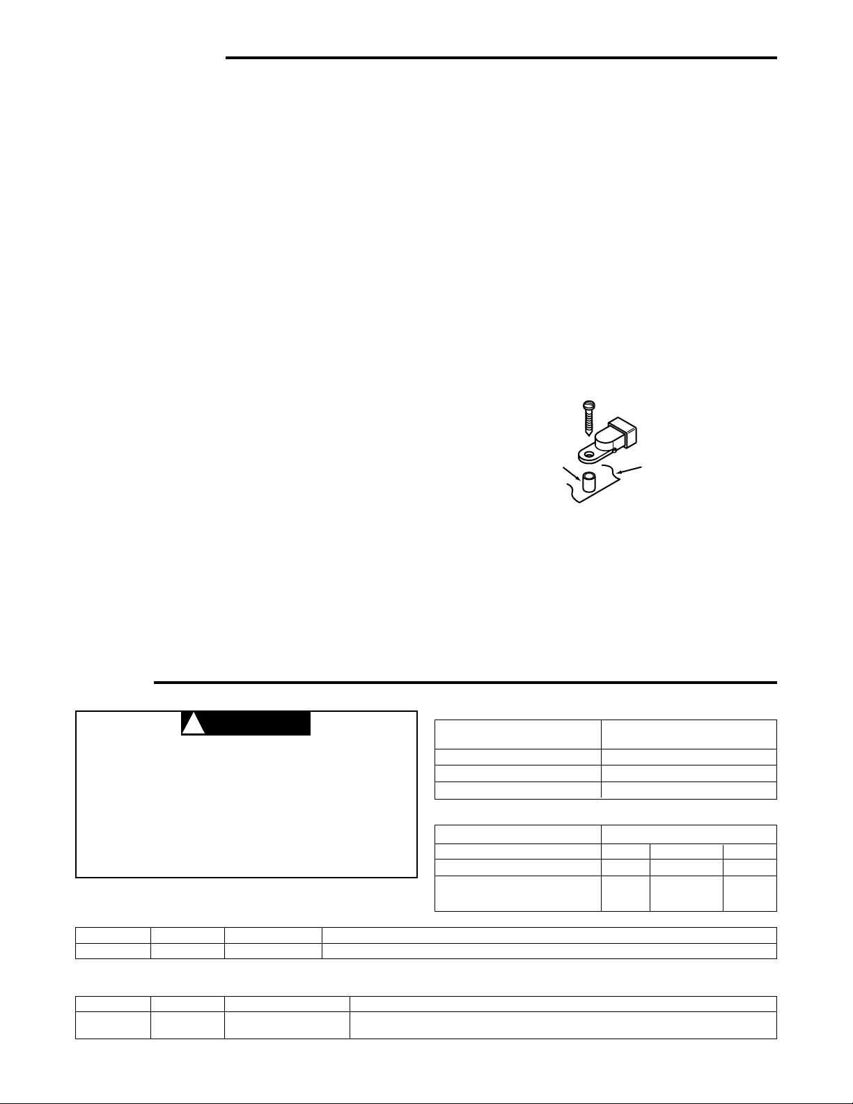
5. Outdoor temperature measurement requires installing the
probe outdoors. Good probe locations would be under a
bay window or overhang, out of direct sunlight. Direct sun
exposure will affect sensed temperature. Install probe with
spacer to obtain a more accurate temperature.
Spacer
Mounting
Surface
maximum maximum
maximum of
maximum maximum
6. Although connected to the probe wire for outdoor temperature sensing, the interior mounting base must be placed
indoorsindoors
indoors. Therefore, the interior mounting base must be
indoorsindoors
installed near the perimeter of the building, so that the
probe wire can be run through to the outside of the
structure and placed in the selected (shaded) location. The
outdoor probe wire is 12 feet long (
or splicedor spliced
or spliced), so plan the placement of both the probe and
or splicedor spliced
interior mounting base accordingly. Any excess wire may
be coiled or bundled. The probe should be connected to E2
as shown in figure 2.
WIRINGWIRING
WIRING
WIRINGWIRING
CAUTION
!
Do not allow the 3-conductor wire to be pinchedDo not allow the 3-conductor wire to be pinched
Do not allow the 3-conductor wire to be pinched
Do not allow the 3-conductor wire to be pinchedDo not allow the 3-conductor wire to be pinched
between the sensor and the wall.between the sensor and the wall.
between the sensor and the wall.
between the sensor and the wall.between the sensor and the wall.
Check wire connections before applying power.Check wire connections before applying power.
Check wire connections before applying power.
Check wire connections before applying power.Check wire connections before applying power.
Improper connections will lead to permanentImproper connections will lead to permanent
Improper connections will lead to permanent
Improper connections will lead to permanentImproper connections will lead to permanent
damage to the sensor.damage to the sensor.
damage to the sensor.
damage to the sensor.damage to the sensor.
20 Gauge Shielded cable must be used. Cable20 Gauge Shielded cable must be used. Cable
20 Gauge Shielded cable must be used. Cable
20 Gauge Shielded cable must be used. Cable20 Gauge Shielded cable must be used. Cable
shield must be connected to "-" or S3 on theshield must be connected to "-" or S3 on the
shield must be connected to "-" or S3 on the
shield must be connected to "-" or S3 on theshield must be connected to "-" or S3 on the
THERMOSTAT ONLY.THERMOSTAT ONLY.
THERMOSTAT ONLY.
THERMOSTAT ONLY.THERMOSTAT ONLY.
INDOOR SENSORSINDOOR SENSORS
INDOOR SENSORS
INDOOR SENSORSINDOOR SENSORS
Model Number Color Dimensions Application
F145-1328 Classic White 21/8" x 31/2" x 3/4" Compatible with all White-Rodgers Thermostats with Indoor Remote Sense
1. 1F93-380, 1F95-371, 1F95-377 and 1F95-391 thermostats average or weight sensor priority in multiple remote applications.
OUTDOOR SENSORSOUTDOOR SENSORS
OUTDOOR SENSORS
OUTDOOR SENSORSOUTDOOR SENSORS
Model Number Color Dimensions Application
F145-1378 Classic White 21/8" x 31/2" x 3/4" Compatible with all White-Rodgers Thermostats with Outdoor Remote Sense
1. Outdoor Sensor provides outdoor temperature to thermostat display. Not used for averaging or cycle rate calculations except on 1F95-391.
with 12 ft. sensor lead
(Thermostat or Remote) (Thermostat or Remote)
`S3 -
*F145-1049, *F145-1170 S1 S2 S3
F145-1328, F145-1378 + S -
*Models no longer available Sensor Sensor Sensor
Connection Cross ReferenceConnection Cross Reference
Connection Cross Reference
Connection Cross ReferenceConnection Cross Reference
Thermostats and Remote SensorsThermostats and Remote Sensors
Thermostats and Remote Sensors
Thermostats and Remote SensorsThermostats and Remote Sensors
Old Terminal New Terminal
S1 +
S2 S
Old/New Remote Terminal DesignationsOld/New Remote Terminal Designations
Old/New Remote Terminal Designations
Old/New Remote Terminal DesignationsOld/New Remote Terminal Designations
Model Number Terminal Designation
Positive Return Signal Negative
and should not be cutand should not be cut
and should not be cut
and should not be cutand should not be cut
2
Page 3

S1 S2 S3
WIRING DIAGRAMSWIRING DIAGRAMS
WIRING DIAGRAMS
WIRING DIAGRAMSWIRING DIAGRAMS
NoteNote
Note: Also connect shield of 20 gauge 3 connector cable
NoteNote
to - or S3 on thermostat subbase.
Remote SensorRemote Sensor
Remote Sensor
Remote SensorRemote Sensor
S1 S2 S3
MV W RH RC G Y O B 6
Thermostat SubbaseThermostat Subbase
Thermostat Subbase
Thermostat SubbaseThermostat Subbase
Figure 1 – Single Stage Thermostat Remote Sensor Wiring (F145-1328)Figure 1 – Single Stage Thermostat Remote Sensor Wiring (F145-1328)
Figure 1 – Single Stage Thermostat Remote Sensor Wiring (F145-1328)
Figure 1 – Single Stage Thermostat Remote Sensor Wiring (F145-1328)Figure 1 – Single Stage Thermostat Remote Sensor Wiring (F145-1328)
PH D SA SB SCOTL
W3A1E2
RCEW2W1Y2Y1BOG
Thermostat SubbaseThermostat Subbase
Thermostat Subbase
Thermostat SubbaseThermostat Subbase
P
SA SB SC OT
+ Terminals
- Terminals
+
S
E2
–
To + or To S1
To S or To S2
To - or To S3
NoteNote
Note: Also connect shield of 20 gauge 3 connector cable
NoteNote
to - or S3 on thermostat subbase.
Remote Outdoor SensorRemote Outdoor Sensor
Remote Outdoor Sensor
Remote Outdoor SensorRemote Outdoor Sensor
+
S
E2
–
Outdoor Probe
To +
To OT
To -
Remote Indoor Sensor ARemote Indoor Sensor A
Remote Indoor Sensor A
Remote Indoor Sensor ARemote Indoor Sensor A
Remote Indoor Sensor BRemote Indoor Sensor B
Remote Indoor Sensor B
Remote Indoor Sensor BRemote Indoor Sensor B
+
S
+
S
E2
–
E2
To To SA
To +
Figure 2 – Staging Thermostat Multi-Stage or Heat Pump Indoor/Outdoor Remote Sensor WiringFigure 2 – Staging Thermostat Multi-Stage or Heat Pump Indoor/Outdoor Remote Sensor Wiring
Figure 2 – Staging Thermostat Multi-Stage or Heat Pump Indoor/Outdoor Remote Sensor Wiring
Figure 2 – Staging Thermostat Multi-Stage or Heat Pump Indoor/Outdoor Remote Sensor WiringFigure 2 – Staging Thermostat Multi-Stage or Heat Pump Indoor/Outdoor Remote Sensor Wiring
(F145-1328/F145-1378)(F145-1328/F145-1378)
(F145-1328/F145-1378)
(F145-1328/F145-1378)(F145-1328/F145-1378)
–
To To SB
To +
Remote Indoor Sensor CRemote Indoor Sensor C
Remote Indoor Sensor C
Remote Indoor Sensor CRemote Indoor Sensor C
To SC
To +
To -
+
S
E2
–
3
Page 4

CONFIGURATIONCONFIGURATION
CONFIGURATION
CONFIGURATIONCONFIGURATION
Comfort-Set IIComfort-Set II
Comfort-Set II
Comfort-Set IIComfort-Set II
Single Stage ModelsSingle Stage Models
Single Stage Models: Verify jumper wire
Single Stage ModelsSingle Stage Models
of the thermostat (not the subbase) has been clipped.
Multi-stage and Heat Pump ModelsMulti-stage and Heat Pump Models
Multi-stage and Heat Pump Models: Verify jumper wire
Multi-stage and Heat Pump ModelsMulti-stage and Heat Pump Models
1818
18 on the back of the thermostat (not the subbase) has
1818
been clipped.
REMOTE SENSOR CALCULATED PRIORITY AVERAGEREMOTE SENSOR CALCULATED PRIORITY AVERAGE
REMOTE SENSOR CALCULATED PRIORITY AVERAGE
REMOTE SENSOR CALCULATED PRIORITY AVERAGEREMOTE SENSOR CALCULATED PRIORITY AVERAGE
1F93-380, 1F94-371, 1F95-371, 1F95-377, 1F95-3911F93-380, 1F94-371, 1F95-371, 1F95-377, 1F95-391
1F93-380, 1F94-371, 1F95-371, 1F95-377, 1F95-391
1F93-380, 1F94-371, 1F95-371, 1F95-377, 1F95-3911F93-380, 1F94-371, 1F95-371, 1F95-377, 1F95-391
Single stage thermostats accept only 1 remote sensor. 90 Series multi-stage and heat pump thermostats accept up to 3
indoor remote sensors and can be assigned sensor priorities.
Tables 1-3 show how priority (LO, AVG, HI) effects the room temperature calculation. The example below table three shows
the calculation of each remote sensor and how it uses them to arrive at room temperature average.
Table 1: Remote Sensor A configured as a LO priority sensorTable 1: Remote Sensor A configured as a LO priority sensor
Table 1: Remote Sensor A configured as a LO priority sensor
Table 1: Remote Sensor A configured as a LO priority sensorTable 1: Remote Sensor A configured as a LO priority sensor
RemoteRemote
Remote
RemoteRemote
SensorSensor
Sensor
SensorSensor
SA LO 1 70°F (Sensor Temp.) 1 x 70 = 70 (Priority Multiplier x Room Temp.)
Table 2: Remote Sensor B configured as a AVG priority sensorTable 2: Remote Sensor B configured as a AVG priority sensor
Table 2: Remote Sensor B configured as a AVG priority sensor
Table 2: Remote Sensor B configured as a AVG priority sensorTable 2: Remote Sensor B configured as a AVG priority sensor
RemoteRemote
Remote
RemoteRemote
SensorSensor
Sensor
SensorSensor
SB AVERAGE 2 75°F (Sensor Temp.) 2 x 75 = 150 (Priority Multiplier x Room Temp.)
SensorSensor
Sensor
SensorSensor
PriorityPriority
Priority
PriorityPriority
SensorSensor
Sensor
SensorSensor
PriorityPriority
Priority
PriorityPriority
PriorityPriority
Priority
PriorityPriority
MultiplierMultiplier
Multiplier
MultiplierMultiplier
PriorityPriority
Priority
PriorityPriority
MultiplierMultiplier
Multiplier
MultiplierMultiplier
W-22W-22
W-22 on the back
W-22W-22
Room TemperatureRoom Temperature
Room Temperature
Room TemperatureRoom Temperature
Room TemperatureRoom Temperature
Room Temperature
Room TemperatureRoom Temperature
W-W-
W-
W-W-
Comfort-Set III/Comfort-Set 90/90 SeriesComfort-Set III/Comfort-Set 90/90 Series
Comfort-Set III/Comfort-Set 90/90 Series
Comfort-Set III/Comfort-Set 90/90 SeriesComfort-Set III/Comfort-Set 90/90 Series
Single Stage ModelsSingle Stage Models
Single Stage Models: Verify jumper wire
Single Stage ModelsSingle Stage Models
back of the thermostat (not the subbase) has been clipped.
You must also enable the remote sensor option in the
Installation Instructions, Configuration Menu.
Multi-stage and Heat Pump ModelsMulti-stage and Heat Pump Models
Multi-stage and Heat Pump Models: When installing a
Multi-stage and Heat Pump ModelsMulti-stage and Heat Pump Models
remote sensor you must enable the remote sensor option in
the Installation Instructions, Installer Menu.
Averaging CalculationAveraging Calculation
Averaging Calculation
Averaging CalculationAveraging Calculation
Averaging CalculationAveraging Calculation
Averaging Calculation
Averaging CalculationAveraging Calculation
W-922W-922
W-922 on the
W-922W-922
Table 3: Remote Sensor C configured as a HI priority sensorTable 3: Remote Sensor C configured as a HI priority sensor
Table 3: Remote Sensor C configured as a HI priority sensor
Table 3: Remote Sensor C configured as a HI priority sensorTable 3: Remote Sensor C configured as a HI priority sensor
RemoteRemote
Remote
RemoteRemote
SensorSensor
Sensor
SensorSensor
SC HI 4 80°F (Sensor Temp.) 4 x 80 = 320 (Priority Multiplier x Room Temp.)
The example below lists three sensors each with a different priority and room temperature. All three sensors are combined in
the calculation to display the average temperature. The priority multiplier shown in the tables above causes a sensor with
low priority to carry less weight in the calculated average. A sensor with a HI priority setting contributes more to the calculated average. Assume that the building in which the thermostat is located has three indoor remote sensors (SA, SB, SC)
that have different room temperatures (70, 75, 80). The calculated average will be displayed as the room temperature
shown in the example below.
Example: Remote Sensors A, B, and C configured as a LO, AVG, and HI priority sensorsExample: Remote Sensors A, B, and C configured as a LO, AVG, and HI priority sensors
Example: Remote Sensors A, B, and C configured as a LO, AVG, and HI priority sensors
Example: Remote Sensors A, B, and C configured as a LO, AVG, and HI priority sensorsExample: Remote Sensors A, B, and C configured as a LO, AVG, and HI priority sensors
RemoteRemote
Remote
RemoteRemote
SensorSensor
Sensor
SensorSensor
SA LO 1 70°F (Sensor Temp.) 1 x 70 = 70 (Priority Multiplier x Room Temp.)
SB AVERAGE 2 75°F (Sensor Temp.) 2 x 75 = 150 (Priority Multiplier x Room Temp.)
SC HI 4 80°F (Sensor Temp.) 4 x 80 = 320 (Priority Multiplier x Room Temp.)
SensorSensor
Sensor
SensorSensor
PriorityPriority
Priority
PriorityPriority
SensorSensor
Sensor
SensorSensor
PriorityPriority
Priority
PriorityPriority
PriorityPriority
Priority
PriorityPriority
MultiplierMultiplier
Multiplier
MultiplierMultiplier
PriorityPriority
Priority
PriorityPriority
MultiplierMultiplier
Multiplier
MultiplierMultiplier
Room TemperatureRoom Temperature
Room Temperature
Room TemperatureRoom Temperature
Room TemperatureRoom Temperature
Room Temperature
Room TemperatureRoom Temperature
Averaging CalculationAveraging Calculation
Averaging Calculation
Averaging CalculationAveraging Calculation
Averaging CalculationAveraging Calculation
Averaging Calculation
Averaging CalculationAveraging Calculation
Avg. Calc. (540)/Sum Priority Mult. (7)
540/7 = 77°F (Calculated Displayed Temp.)
4
Page 5

REMOTE SENSOR TROUBLESHOOTING GUIDEREMOTE SENSOR TROUBLESHOOTING GUIDE
REMOTE SENSOR TROUBLESHOOTING GUIDE
REMOTE SENSOR TROUBLESHOOTING GUIDEREMOTE SENSOR TROUBLESHOOTING GUIDE
Comfort-Set IIComfort-Set II
Comfort-Set II
Comfort-Set IIComfort-Set II
Single Stage ModelsSingle Stage Models
Single Stage Models: Verify jumper wire
Single Stage ModelsSingle Stage Models
of the thermostat (not the subbase) has been clipped.
Multi-stage and Heat Pump ModelsMulti-stage and Heat Pump Models
Multi-stage and Heat Pump Models: Verify jumper wire
Multi-stage and Heat Pump ModelsMulti-stage and Heat Pump Models
W-18W-18
W-18 on the back of the thermostat (not the subbase) has
W-18W-18
been clipped.
To function correctly and read temperature accurately, the thermostat (when set up for a remote as outlined above) must
have constant 24-volt power. If the thermostat temperature is steadily dropping, reading low, or reads
sensor is installed, it can be traced to one of the three following conditions.
ConditionCondition
Condition
ConditionCondition
1. Loss of 24-volt power. On models with batteries, remove the batteries and re-install For the sensor to read correctly,
thermostat. If the display is blank, check heating and cooling the 24-volt system power
system to determine why 24-volt power is absent. be present. Some systems may
2. A broken wire on S1, Disconnect sensor wires at thermostat. Attach a short piece Repair or replace the 3 wire
S2 and S3 or (+, SA, -) (2') of three-wire shielded cable to S1, S2 and S3 or (+, SA, shielded cable. Be sure the
from the thermostat to -) on the subbase. Bring the remote sensor to the thermostat remote wire run is not parallel
the remote. location and attach S1, S2 and S3 or (+, S, -) respectively. to line voltage wires that carry
Reattach thermostat. If the temperature begins to climb heavy inductive loads, or across
(slowly), it is reading correctly. If it reads correctly with the 2' fluorescent light ballasts that
length but improperly when attached to the wire run, it may cause an inductance to be
indicates a fault in the wire run. transmitted to the thermostat.
3. A shorted or Because it is an electronic sensor, there are no Ohm values Replace remote sensor.
damaged remote sensor. to test. If correct conditions as listed in 1 & 2 above and the
temperature stays at or near
damaged remote sensor.
W-22W-22
W-22 on the back
W-22W-22
Troubleshooting ChartTroubleshooting Chart
Troubleshooting Chart
Troubleshooting ChartTroubleshooting Chart
TestTest
Test
TestTest
08°08°
08°, it indicates a shorted or
08°08°
Comfort-Set III/Comfort-Set 90/90 SeriesComfort-Set III/Comfort-Set 90/90 Series
Comfort-Set III/Comfort-Set 90/90 Series
Comfort-Set III/Comfort-Set 90/90 SeriesComfort-Set III/Comfort-Set 90/90 Series
Single Stage ModelsSingle Stage Models
Single Stage Models: Verify jumper wire
Single Stage ModelsSingle Stage Models
back of the thermostat (not the subbase) has been clipped.
You must also enable the remote sensor option in the
Installation Instructions, Configuration Menu.
Multi-stage and Heat Pump ModelsMulti-stage and Heat Pump Models
Multi-stage and Heat Pump Models: When installing a
Multi-stage and Heat Pump ModelsMulti-stage and Heat Pump Models
remote sensor you must enable the remote sensor option in
the Installation Instructions, Installer Menu.
require an isolation relay to provide constant power to the
thermostat. Limit or safety
devices in the equipment can
also cause a power interruption.
W-922W-922
W-922 on the
W-922W-922
08°08°
08° when a remote
08°08°
CommentsComments
Comments
CommentsComments
mustmust
must
mustmust
NoteNote
Note: Digital thermostats and remote sensors acclimate very slowly to temperature change. It may take an hour or more for
NoteNote
the temperature to acclimate to the room temperature from a low temperature reading as outlined above. To expedite the
room temperature display use the reset instructions listed in the installation instructions for the thermostat model you are
working with. When reset, the thermostat will default to a room temperature of 70° and begin sensing room temperature. Be
sure to reconfigure the installer menu for a remote sensor because the reset function may cancel remote sensing.
5
Page 6

The Emerson logo is a
trademark and service mark
of Emerson Electric Co.
 Loading...