

Page 1
Electronic Air Cleaner
Model Number
CSC1000
UL Listed
CSA Certified
OWNER’S MANUAL
• Installation
• Operation
• Basic Service Guide
• Technical Repair Guide
• Repair Parts
Please read and familiarize yourself with the contents of this manual before
installing, operating or performing maintenance on the unit.
White-Rodgers is a division
of Emerson Electric Co.
www.white-rodgers.com
Printed In U.S.A.
PART NO. 37-6336A
Replaces 846-0273
0102
Page 2
RULES FOR SAFE
INSTALLATION AND OPERATION
Please read instructions before installing and using the Electronic Air Cleaner. This will help you obtain the full benefit from
the Electronic Air Cleaner you have selected.
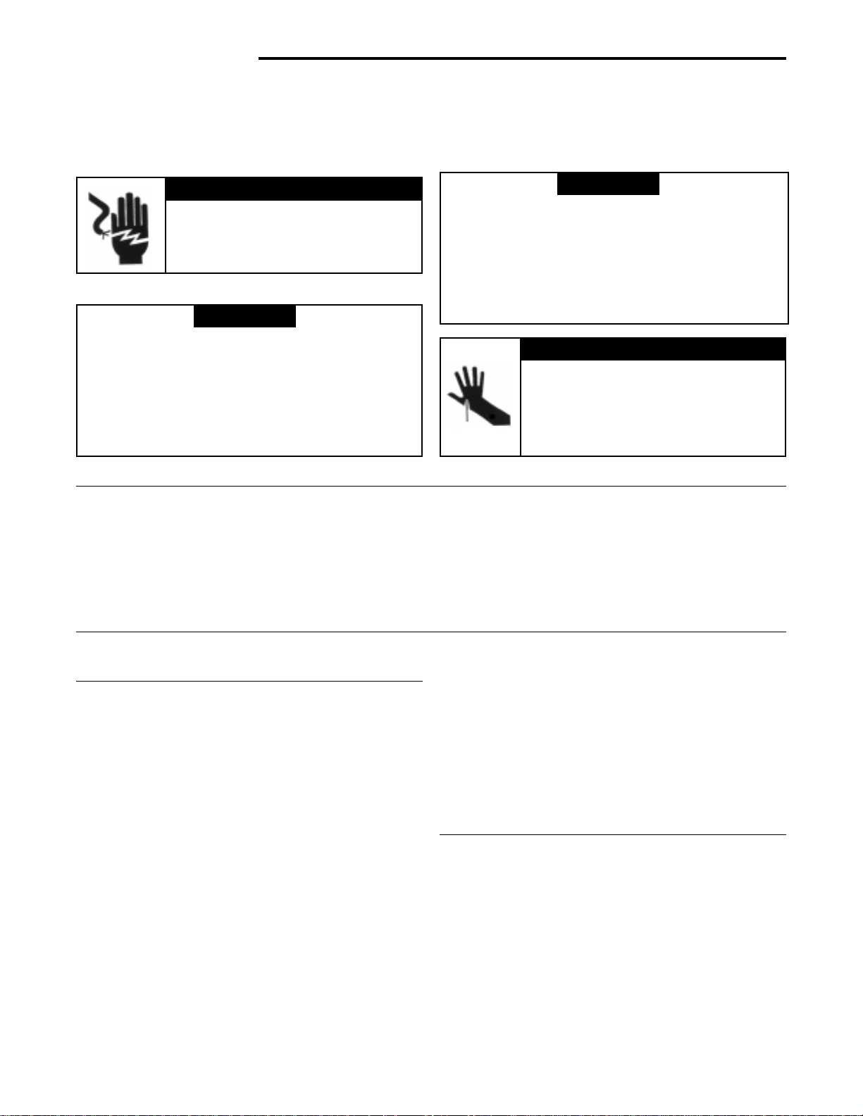
! WARNING
▲
ELECTROCUTION HAZARD
Shut off power at fuse panel before
servicing. Failure to do so could result
in serious personal injury or death.
! WARNING
▲
Do not attempt installation of this unit unless you are
familiar with the necessary tools, equipment, utility
connections and potential hazards.
Installation should be performed only by a qualified
service provider.
Failure to do so could result in reduced performance
of the unit, serious personal injury or death.
1. Read the Owners Manual and the Rules for Safe
Operation carefully. Failure to follow these rules and
instructions could cause a malfunction of filter or
unsatisfactory service.
2. Follow a regular service and maintenance schedule
for efficient operation.
! WARNING
▲
Installation of this unit must comply with local electric
codes or other applicable codes.
Review and understand local codes prior to installation.
Do not use this apparatus in an explosive atmosphere.
Failure to do so could result in serious personal injury
or death.
! CAUTION
▲
CABINET AND CELLS MAY CONTAIN
SHARP EDGES.
Use care when servicing unit or handling
cells. Failure to do so could result in
minor personal injury.
Specifications
CSC1000 Self-Contained Ceiling Hung Electronic Air Cleaner
Model: CSC1000
Voltage: 120 VAC, 60 Hz.
Watts HI-speed: 240
Fan Speed: Variable 200 to 1000 CFM
Dimensions: 28”H x 28”W x 111/2”D
Basic Tools Required
Screwdriver, Rule or Tape Measure, Drill
HOW THE AIR CLEANER WORKS
The enclosed fan circulates the air through the bottom of the
electronic air cleaner and out through the four outlet grilles. The
ionizing section of the collecting cell contains many fine ionizing
wires that charge the incoming airborne particles. The charged
particles move into the collecting plate area and are trapped to the
plates (like a magnet attracts and collects iron filings).
The cleaned air is then drawn through a charcoal filter to assist in
removal of unpleasant odors. The cleaned and purified air is
discharged to recirculate through your building.
White Dust (Lint)
An Electronic Air Cleaner is designed to collect two major types of
contaminants: ➀ Irritants (Pollens, Spores, Molds, Bacteria, etc.)
and ➁ Black Soiling Contaminants (Dirt and Smoke particles).
The residue on the collecting plates of an electronic air cleaner is
black, indicating it is removing dirt from the air stream. After
installing an air cleaner you may notice white dust (typically, long
linty particles or fibers – from carpets, cotton materials or drapery
fabrics). This material is not collected by the air cleaner because it
does not contain the irritants or soiling contaminants listed above or
settles out of the air before reaching the air cleaner. The presence of
white dust does not indicate an air cleaner requires service.
Weight: 66 lbs.
Shipping Weight: 76 lbs.
Efficiency: Efficiency varies with fan speed approximately 96%
at low speed and 87% at hi speed.
NOTE: Unit must run for one full hour after installation. This will
allow the collecting cells to reach peak efficiency.
Table of Contents
Rules for Safe Installation and Operation . . 2
How the Air Cleaner Works . . . . . . . . . . . . . 2
Installation . . . . . . . . . . . . . . . . . . . . . . . . . . 3
Operation/Maintenance . . . . . . . . . . . . . . . . 4
Technical Repair Guide . . . . . . . . . . . . . . . . 5
Repair Parts . . . . . . . . . . . . . . . . . . . . . . . . . 7
Wash Reminder . . . . . . . . . . . . . . . . . . . . . . 8
Carbon (Charcoal) Filters
Odors are gas molecules, not particles. They cannot be removed by
an Electronic Air Cleaner or by any other filtration media designed to
remove airborne particles. However, some gases can be absorbed
by an activated carbon filter or diluted with fresh outdoor air. When
odors are present, the addition of charcoal filters will neutralize
odors, such as cooking odors, pet odors, cigar and cigarette odors,
ozone, etc. Optional charcoal filters are available for your Air
Cleaner. Refer to the parts list for the charcoal filter part number for
your Air Cleaner. Charcoal filters require replacement. They cannot
be washed. While there is no rule of thumb for how often they should
be changed, you can use your best judgement based on the odors
you perceive in your environment.
2
Page 3
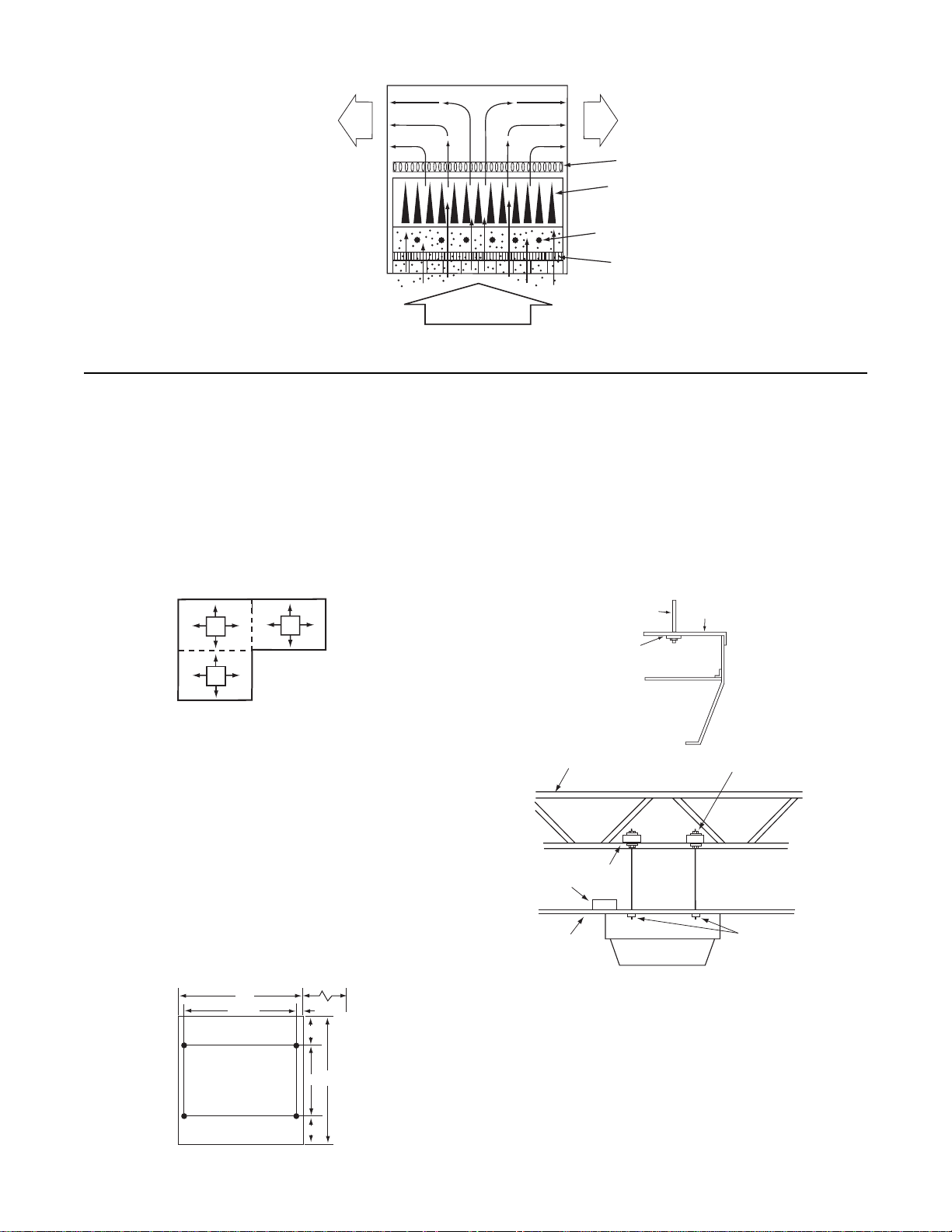
Clean
Air Out
FIG. 1 Illustration of Air Cleaning Process
INSTALLATION
PLACEMENT
The installer must be qualified to make approved electrical
connections and a safe ceiling installation with attention to the
best placement as shown in the following drawings.
The electronic air cleaner should be mounted on the ceiling near
the center of the room. Air is drawn through the bottom of the air
cleaner and discharged in four directions. Divide larger rooms
into sections and use a unit in each section (see Fig. 2).
Clean
Air Out
Charcoal Filter
Reduces Odors
Collecting Plates attract
and hold dirt particles
like a magnet
Ionizing wires give dirt
particles a positive charge
Prefilter Screen
DIRTY
AIR IN
Mounting Detail
Be sure to select the mounting location so that the structure
above is sufficiently strong to support the unit (approximately 70
lbs). See Fig.4.
CAUTION: Do not allow the unit to be supported by the
ceiling tile grid suspension.
FIG. 2 Divide large room into areas
Check existing air circulation in the room. The air cleaner should
be installed so that it aids the circulation already established.
When air flow patterns are not immediately apparent, observe
the smoke from a cigarette in various locations within the room.
Do not locate the air cleaner near a heating or air conditioning
intake or exhaust vent if it interferes with the air flow discharge
and return air to the heating or air conditioning unit.
CEILING MOUNT
The air cleaner is mounted to the ceiling. The mounting holes in
the unit are spaced 16” and 261/2” between centers (Fig. 3).
ALLOW AT LEAST 14" (356 mm)
FOR CELL REMOVAL
28
26 1/2
TOP
3/4
6
FRONT
28
16
ROOF SUPPORT JOIST
ALTERNATE 2X4
MOUNTING METHOD
FALSE
CEILINGS
**ALTERNATIVE: Wood 2 x 4's can be used at the
False Ceiling Level and supported from above with
3/8 " DIA. STEEL
THREADED ROD
WELD NUT
2X4
16 ga. wire min.
COVER
NUT & WASHER TOP AND BOTTOM
HANG THE AIR CLEANER
FROM THE TREADED STEEL
RODS TO T OP PLA TE
WELD NUTS
FIG. 4 Mounting details
6
FIG. 3 Installation Dimensions in Inches
3
Page 4

WIRING INSTRUCTIONS
Standard electrical wiring of 120 volts, 60 Hz, 15 Amp circuit is
adequate. Local residential and commercial wiring codes shall
apply. Flexible conduit should be used (Fig. 5).
OPERATION/MAINTENANCE
OPERATION
TOP OF
UNIT
BOX (INTERNAL)
GREEN
WHITE
BLACK
FIG. 5 Electrical connection
FIELD GROUND
FIELD NEUTRAL
FIELD HOT
1. With the 120 VAC power turned on, adjust the knob to the
position desired.
2. When the fan is running, the air cleaner will be operating.
An arcing or “snapping” sound may be heard occasionally, however the unit is operating properly.
WASHING
! CAUTION
▲
CABINET AND CELLS MAY CONTAIN
SHARP EDGES.
Use care when servicing unit or handling
cells. Failure to do so could result in minor
personal injury.
For maximum efficiency, your air cleaner cell and pre-filter
should be inspected periodically and cleaned when necessary. The cleaning frequency will vary, depending on the
amount of airborne contaminants. When cleaning is required
the following procedure should be used:
CLEANING THE CELL
1. Turn the control switch to “OFF”.
2. Open the door, slide out charcoal filter, cell and pre-filter
and re-close the door for safety. Replacement charcoal
filters are available for odor control (see parts list).
NOTE: Do not wash the charcoal filter.
3. Using a solution of warm water and low sudsing
detergent, soak cell for 20 to 30 minutes.
NOTE: Ionizing wires may become coated, causing loss
of cleaning ability by the collecting cell. Using a damp
cloth, wipe each ionizing wire, exercising care not to
damage them.
3. The Operating Light should be ON whenever the fan is
running. An occasional flicker of the light accompanied
by harmless sparking or snapping noise may occur. This
is caused by the plates trapping large particles. If arcing
is continuous, the cells should be washed or checked
for service problems.
4. Remove the cell from solution and rinse thoroughly with
clean water. After removing cell, wash and rinse prefilter.
5. Allow cell and pre-filter to drip dry for a minimum of
2 hours. Cell may be tipped at a slight angle to expedite
the drip-dry process.
6. Open door and replace charcoal filter.
7. Slide cell into unit with air flow arrow pointing in direction
of air flow.
8. Slide pre-filter screen into unit.
9. Close the door and securely fasten.
10.Turn the control switch to desired fan speed.
A moderate amount of arcing or “snapping” may occur at
this time, which will indicate that the cell is still damp. If
the noise is objectionable, turn the control switch to “OFF”
and allow additional time for the cell to dry.
4
Page 5

TECHNICAL REPAIR GUIDE
! WARNING
▲
Do not attempt repair of this unit unless you are
familiar with the necessary tools, equipment, utility
connections and potential hazards.
Repair should be performed only by a qualified
service provider.
Failure to do so could result in reduced performance
of the unit, serious personal injury or death.
SERVICE INDICATION SERVICE CHECKS
Control switch “ON” Unit functioning Normally.
Fan operating
Operating Light ON
Control switch “ON” 1. Power is not being supplied to air cleaner.
Fan not operating A. Check fuse or circuit breaker.
Operating Light OFF B. Make sure that door is closed and safety switch is pushed in.
This guide contains service checks to assist service personnel
in locating and correcting any malfunction that might occur to
render the air cleaner ineffective or inoperative. The air cleaner
has been designed with replaceable components, such as the
high-voltage power supply. This allows the serviceman to
replace a faulty component rather than attempt repairs of such
components in the field.
Excessive arcing during 1. Collecting cell dirty.
normal operation – A. Clean cell thoroughly as instructed in this manual.
Operating Light may blink 2. Wet collecting cell.
A. Allow cell to dry after cleaning before applying power.
NOTE: Occasional arcing 3. Excessive airborne material.
or “snapping” is considered A. Additional air cleaner(s) may be required in extreme environments.
normal. B. Additional clean make-up air may be required.
4. Damaged or shorted collecting cell.
A. Inspect cell for bent plates. Straighten plates as necessary.
B. Check for foreign objects shorting across cell plates or ionizing section.
C.Inspect cell for loose or broken ionizing wire(s). Replace as needed.
D. Inspect cell for cracked or broken insulator(s), around cell perimeter.
Replace collecting cell if condition persists.
5. Damaged charcoal filter.
A. Remove charcoal filter. If arcing/snapping stops, the filter may be
breaking down and require disposal or replacement.
Control switch “ON” 1. Damaged or shorted collecting cell.
Fan operating A. Remove collecting cell. Close door so safety switch is pushed in.
Operating Light OFF If Operating light comes ON with cell removed, check cell as described
above. If light does not come ON, proceed to next step.
2. Power Supply.
A. Remove collecting cell. With safety switch pushed in, 120 VAC should
be present at terminals marked “LINE” on power supply. If voltage is
below 6100 VDC at red high voltage terminal on power supply, replace
power supply. If voltage is correct, replace indicator light.
NOTE: Unit may require up to one hour of operation to reach indicated
voltage when first installed or when replacing cell.
5
Page 6

OZONE REDUCTION
All electronic air cleaners typically produce a small amount of
ozone that is within established limits. Some customers may
notice an odor especially at high altitudes or low air flow rates.
This power supply has a “hairpin” shaped jumper wire labeled
W1 that can be cut and separated in case of such complaints.
This will cause the power supply to limit the maximum operating
power to a lower level.
CSC1000
WIRING DIAGRAM
W1
WHT/BRN BLK
E3 E2
LINE
Cut and separate
Ozone Reduction
Jumper
6
Page 7

REPLACEMENT
PARTS DIAGRAM
6
7
11
3
9
2
1
5
4
10
8
ITEM NO. DESCRIPTION CSC1000
1 Pre-Filter F825-0357
2 Collecting Cell F811-0414
3 Power Supply † F858-1002
4 Switch, Safety F876-0199
5 Switch, Variable Speed F876-0203
6 Fan Motor F849-0060
7 Fan Blade F848-0315
8 Charcoal Filter F825-0460
9 Light F844-0143
10 Knob F839-0019
11 Ionizing Wire F843-0500
†† Manual 37-6336
† F858-1002 Kit includes Air Flow Switch not used on this model
††Not Shown
7
Page 8

WASH REMINDER SCHEDULE
A regular washing schedule is necessary to ensure proper
efficiency. A thorough washing once every month will be adequate for most installations. More or Less
frequent washing may be necessary on some installations
where there is new carpeting, plaster dust or excessive cigarette
smoke, etc. (See page 4 for maintenance and instructions on
how to clean a cell.)
Year JAN FEB MAR APR MAY JUN JUL AUG SEP OCT NOV DEC
20___
20___
20___
20___
20___
20___
20___
20___
20___
20___
20___
20___
NOTICE TO CONSUMERS
White-Rodgers
Electronic Air Cleaner
Dear Consumer;
White-Rodgers would like to thank you for purchasing a White-Rodgers Electronic Air Cleaner or
product containing a White-Rodgers Electronic Air Cleaner. Although White-Rodgers does not extend
a warranty directly to consumers, White-Rodgers does extend a warranty to Wholesalers and Original
Equipment Manufacturers who use White-Rodgers Products. To obtain more information about how
your Wholesaler or Original Equipment Manufacturer’s warranty may benefit you, please contact your
Wholesaler or Original Equipment Manufacturer.
Sincerely,
White-Rodgers
The Emerson logo is a
trademark and service mark
of Emerson Electric Co.
 Loading...