

White Rodgers 1F97W-71 User Manual

WHITE-RODGERS
CAUTION
!
WARNING
!
Operator: Save these instructions for future use!
FAILURE TO READ AND FOLLOW ALL INSTRUCTIONS CAREFULLY
BEFORE INSTALLING OR OPERATING THIS CONTROL COULD CAUSE
PERSONAL INJURY AND/OR PROPERTY DAMAGE.
This wall-mounted, low voltage thermostat maintains
room temperature by controlling the operation of heating
and cooling systems. The user may program up to four
time/temperature settings per 24 hour period. The thermostat stores independent heating and cooling programs
for each day of the week. The thermostat will store both
heating and cooling programs simultaneously. Three
"AA" Energizer® batteries will maintain the stored program for approximately one year, if incoming power
should fail. If power failure is extensive and the program
is lost, after power restoration, the thermostat will automatically maintain a factory preprogrammed heating temperature of 64°F or a cooling temperature of 82°F.
1F97W-71
7-Day Electronic Digital Thermostat
INSTALLATION INSTRUCTIONS
DESCRIPTION
WHITE-RODGERS
If in doubt about whether your wiring is millivolt, line, or low
voltage, have it inspected by a qualified heating and air
conditioning contractor, electrician, or someone familiar
with basic electricity and wiring.
CONTENTS
Description......................................................... 1
Precautions........................................................ 1
Specifications..................................................... 2
Installation.......................................................... 2
New Installation
Select Thermostat Location
Route Wires to Location
Replacement Installation
Remove Old Thermostat
Attach Subbase to Wall
Attach Thermostat to Subbase
Operation ........................................................... 6
System Configuration
A. Set Group A Option Switches
B. Set Group B Option Switches
C. Electric Heat Systems
Check Thermostat Operation
Fan Operation
Heating System
Cooling System
Troubleshooting
PRECAUTIONS
Do not exceed the specification ratings.
All wiring must conform to local and national electrical
codes and ordinances.
This control is a precision instrument, and should be
handled carefully. Rough handling or distorting components could cause the control to malfunction.
To prevent electrical shock and/or equipment
damage, disconnect electric power to system, at
main fuse or circuit breaker box, until installation
is complete.
Do not use on circuits exceeding specified voltage. Higher voltage will damage control and
could cause shock or fire hazard.
Do not short out terminals on gas valve or primary control to test. Short or incorrect wiring will
burn out thermostat and could cause personal
injury and/or property damage.
WHITE-RODGERS DIVISION
EMERSON ELECTRIC CO.
9797 REAVIS ROAD
ST. LOUIS, MISSOURI 63123
R
PART NO. 37-5091A
Printed in U.S.A.
9139

SPECIFICATIONS
ELECTRICAL DATA
Electrical Rating:
17 to 30v AC 50/60 Hz.
0.05 to 1.5 Amps
1.5 Amps Maximum Total Load (All terminals
combined)
Anticipation:
Heating 2 to 40
Cooling 4 to 40
Reference Values
}
THERMAL DATA
Setpoint Temperature Range:
40° F to 99°F (4°C to 37° C)
Operating Ambient Temperature Range:
32°F to 105°F
Operating Humidity Range:
0 to 90% RH (non-condensing)
INSTALLATION
NEW INSTALLATION
You should program the thermostat with batteries
installed before attaching on subbase. See OPERATION GUIDE for programming instructions.
SELECT THERMOSTAT LOCATION
Proper location insures that the thermostat will provide a
comfortable building temperature. Observe the following
general rules when selecting a location:
1. Locate thermostat about 5 ft. above the floor.
2. Install thermostat on a partitioning wall, not on an
outside wall.
3. Never expose thermostat to direct light from lamps,
sun, fireplaces or any temperature radiating equipment.
4. Avoid locations close to windows, adjoining outside
walls, or doors that lead outside.
5. Avoid locations close to air registers or in the direct
path of air from them.
6. Make sure there are no pipes or duct work in that part
of the wall chosen for the thermostat location.
7. Never locate thermostat in a room that normally
warmer or cooler than the rest of the building.
8. Avoid locations with poor air circulation, such as
behind doors or in alcoves.
Shipping Temperature Range:
-40°F to 150°F
APPLICATIONS
For use with:
• Standard heat/cool, heat-only, or cool-only systems
• Three-wire zone valve systems
• Millivolt systems
• Electric heat systems
• Gas or oil fired systems
• Gas systems with intermittent ignition devices
(I.I.D.) and/or vent dampers
Do not use with:
• Multi-stage systems
• Heat pump systems
• Systems exceeding 30v AC and 1.5 Amps
ACCESSORIES
Remote Sense Kit W. R. Part No. F145-1049
Thermostat Guard W. R. Part No. F29-0198 (clear) or
F29-0238 (opaque)
1. Probe for obstructions in partition before drilling 1/2"
hole in wall at selected location. Take up quarter
round and drill a small guide hole for sighting (see Fig.
1). From basement, drill 3/4" hole in partition floor
next to guide hole. In basementless buildings, drill
1/2" hole through ceiling and into partition from above.
2. Through this hole drop a light chain, or 6" chain
attached to a strong cord. Snag cord in basement
with hooked wire. In basementless buildings, drop
cord through hole in ceiling and down partitioning;
snag cord at the thermostat location.
3. Attach thermostat wire to cord and pull wire through
hole in wall so that 6" of wire protrudes.
1/2" HOLE FOR
THERMOSTAT WIRE
STOUT CORD WITH 6"
CHAIN ATTACHED
BASEBOARD
STRIP MOLDING
QUARTER ROUND
REMOVED
1/4" GUIDE HOLE
FOR SIGHTING
APPROXIMATELY
5 FEET
ROUTE WIRES TO LOCATION
NOTE
All wiring must conform with local and national electrical
codes and ordinances.
2
3/4" HOLE IN FLOOR OF PARTITION
Figure 1. Routing Thermostat Wires
HOOKED WIRE FOR SNAGGING CHAIN
REPLACEMENT INSTALLATION
REMOVE OLD THERMOSTAT
1. Shut off electricity at the main fuse box until installation is complete. Verify power is off with a voltmeter.
2. Remove the front cover of the old thermostat. With
wires still attached, remove wall plate from the wall.
3. If the old thermostat has a wall mounting plate,
remove the thermostat and the wall mounting plate as
an assembly.
4. FOR HEATING ONLY SYSTEMS — Disconnect the
two wires from the old thermostat. Skip steps 5
through 7 below and proceed to ATTACH SUBBASE
TO WALL.
5. FOR HEATING/COOLING SYSTEMS — Before re-
moving wires from old thermostat, identify the terminals that have wires attached on the old thermostat.
Then use Table 1 to identify the type of thermostat you
are replacing. For example, if the old thermostat has
wires attached to terminals R, W, Y, and G, the old
thermostat is a type 5 (note that the old thermostat
may not have wires attached to all the terminals
identified in Table 1).
6. Use the self-adhesive labels enclosed with your
new thermostat to identify the wires attached to
the old thermostat. The labels correspond to the
thermostat type number you identified in step 5 above
(see Table 2). For example, if you determined that the
old thermostat is a type 5, use the labels for the type
5 thermostat (you may not use all the labels for the
type number you've identified if the old thermostat did
not have wires attached to all the terminals).
7. Label each wire as you disconnect it. The labels have
both the old terminal markings and the new terminal
identification. Discard any unused labels. PULL AT
LEAST SIX INCHES OF WIRE OUT OF THE WALL
WHEN YOU DISCONNECT IT - DO NOT ALLOW
THE WIRES TO FALL BACK INTO THE WALL.
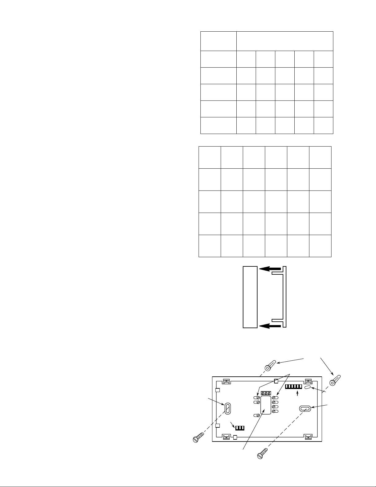
TABLE 1. OLD THERMOSTAT IDENTIFICATION
OLD
THERMOSTAT
TYPE
Type
1
Type
2
Type
3
Type
4
Type
5
RH
R5
OLD THERMOSTAT
TERMINAL IDENTIFICATION
4
W
RC
W
RC
M
H
V
4
R
W
Y
Y
C
Y6
Y
G
G
F
G
G
TABLE 2. WIRE IDENTIFICATION LABELS
Type
Type
Type
Type
Type
1
2
3
4
5
New Old
RH 4
New Old
RH RH
New Old
RH M
New Old
RH R5
New Old
RH R
New Old
W W
New Old
W W
New Old
W H
New Old
W 4
New Old
W W
New Old
RC RC
New Old
RC RC
New Old
RC V
New Old
Y Y
New Old
Y Y
New Old
Y C
New Old
Y Y6
New Old
Y Y
New Old
G G
New Old
G G
New Old
G F
New Old
G G
New Old
G G
ATTACH SUBBASE TO WALL
1. Remove the packing material from the thermostat.
Place the fingers of one hand on the center top and
bottom portion of the thermostat. Grasp the subbase
in the other hand on the top and bottom center, and
gently pull straight out (see Fig. 2). The thermostat
has pin and socket connectors. Forcing or prying on
the thermostat will cause damage to the unit.
2. Pull wires through opening in the center of the subbase. DO NOT LET WIRES FALL BACK INTO
WALL.
3. Connect wires beneath terminal screws on subbase
using appropriate wiring schematic (see Figs. 3
through 11).
4. Place subbase over hole in wall and mark mounting
hole locations on wall using subbase as a template.
(Installation instructions continue on page 5.)
PULL STRAIGHT OUT
Figure 2. Removing thermostat from subbase
Connect wires under
terminal screws
Mounting
Hole
3-pin Connector
Pull wires through
this opening
S1 S2 S3
6
MV
RH
W
6-pin Connector
RC
G
Y
Figure 3. Subbase
Expansion
Plugs
Activity
Light
Mounting
Hole
3
 Loading...