

Whirlwind QBOX AES Users Manual
box-aes
Q
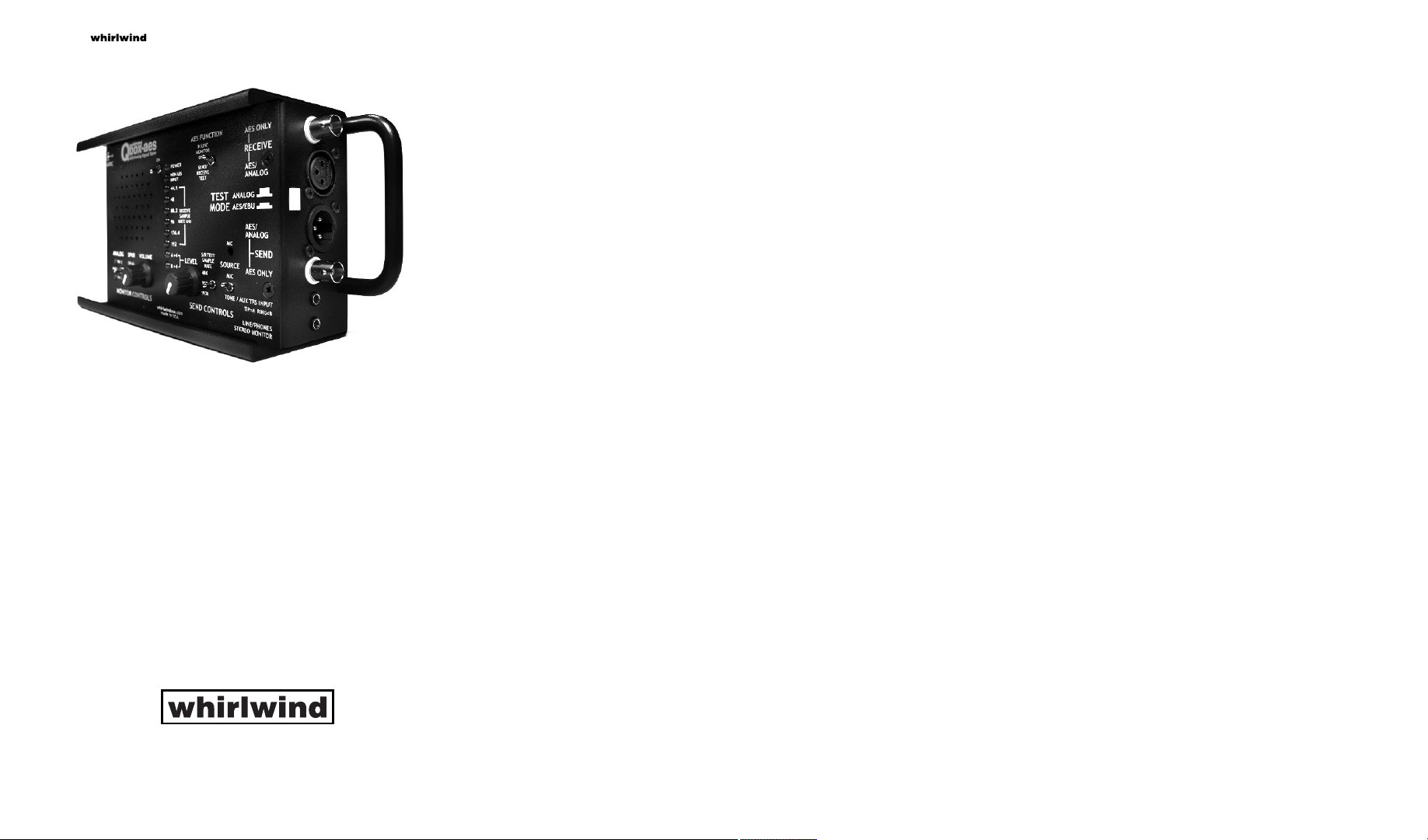
The Whirlwind Qbox-aes is a multipurpose testing device for
troubleshooting digital AES-3, S/PDIF and analog audio signals. It is
composed of two sections; a Send section and a Receive/Monitor
section. A Test Mode switch selects Analog or AES testing operation.
Audio is decoded and output through the built-in speaker or the
3.5mm jack. Test signals can be generated from multiple sources. In
Line monitoring of an AES data stream is also possible with no
alteration of the signal passing through.
Warranty
This product is guaranteed for 5 years from the date of purchase against
manufacturing defects. For warranty service, return the unit, along with
the original sales receipt, to: whirlwind, 99 Ling Road, Rochester, NY
14612, postage prepaid. We will repair or replace the unit at our option
and pay the return postage.
05/2017
AES/ An al og Si gn al Tes te r
99 Ling Road . Rochester, NY 14612
Phone 585 663-8820 . Fax 585 865-8930
Email: sales@whirlwindusa.com
http://www.whirlwindusa.com
Theory of Operation
AES/EBU TEST MODE
The Qbox-aes is designed to provide a portable means of testing various
aspects of AES-3 and S/PDIF digital audio systems. With the Test Mode
switch in the AES/EBU (IN) position, it is able to generate AES-3 or
S/PDIF output signals at sample frequencies of 48 kHz, 96 kHz and 192
kHz. Audio sources for the Send function include a built-in microphone,
a pair of tone generators (440 Hz for the left channel, 660 Hz for the
right), and a 3.5mm, unbalanced stereo input, for an MP3 or CD player,
computer sound card, etc. A Send Level control adjusts the selected
source level into the digital encoder for output through the Send
jacks.The Qbox-aes is capable of decoding professional and consumer
AES-3 or S/PDIF signals, displaying sample frequencies from 44.1 kHz
to 192 kHz and monitoring the audio content via the built-in speaker or
Line/Phones Monitor jack. There are two digital operating modes
available: Send/Receive Test and In Line Monitor as selected by the AES
Function switch. Each of these modes is described in detail in the
following paragraphs.
Send/Receive Test function
When using Send/Receive Test mode, the internal digital receiver will
lock to useable AES-3 or S/PDIF signals applied to the input connectors.
When locked, the appropriate Receive Sample Rate LED will indicate
the detected sample rate. The Non AES Input LED illuminates anytime
that the digital input signal is a non-PCM format, and cannot be decoded
as audio or when the input is analog. The digital audio is decoded and
presented to both the speaker and the Line/Phones Monitor jack. The
digital Send section will convert the selected test signal (mic, aux or
tone) to digital format and output it from the digital Send jacks at the
sample rate set by the S/R Test Sample Rate switch (48, 96 or 192 kHz).
The Send Level control adjusts the amount of output signal delivered to
the Send jacks. There are two green LEDS that illuminate when the
analog input to the A/D converter reaches +4 dB. This results in a digital
output of approximately -12 dBfs. With the level control at full clockwise
the digital output is equal to 0.6 dBfs when using the internal oscillators
as a signal source.
Send/Receive Test mode can be used for cable testing. The selected
test signal is driven out of the digital Send at the sample rate selected by
the sample rate switch. If a good cable is connected between the Send
and Receive, the Sample Rate indicators will display the detected
sample rate and the selected test signal will be heard over the speaker
and the line output. When testing a cable to determine if it has highfrequency problems, select the highest sample rate. If the digital
receiver is able to lock to the signal, chances are that the cable is good.
If the cable has integrity problems, it may not lock at a rate of 192kHz, but
may lock at a lower sample rate. Connecting a short cable between Send
and Receive also provides an excellent means of performing an end-toend test of the Qbox-aes itself, allowing the operator to test the
functionality of all the internal components.
In line Monitor Only function
In Line Monitor mode is used to monitor a digital audio signal without
interrupting its destination, essentially acting as a wiretap. The digital
audio input signal is decoded and the serial data stream is fed to the
digital-to-analog converter for analog monitoring and to the digital output
encoder for re-transmission without passing through the analog domain.
To use this mode, the signal source cable is connected to one of the
digital Receive connectors, and the signal destination cable is
connected to one of the digital Send connectors. When the input signal
is present, the appropriate Sample Rate indicator will illuminate and the
input signal will be present on the digital output connector. The input
signal, in analog format, is available at the speaker and the Line/Phones
Monitor jack. Any analog input sources are ignored, as well as the S/R
Test Sample Rate switch.
Receive/Monitor Section
The Receive Sample Rate LEDs indicate the detected sample rate when
they are locked to the digital input. Only one LED will be illuminated at a
time, except during the Power-On Self-Test. Displayed sample rates are
44.1kHz, 48kHz, 88.2kHz, 96kHz, 176.4kHz, and 192kHz. The Qboxaes can detect both versions of the AES-3 bitstream; professional and
consumer.
Analog monitoring of the digital input signal is done through the internal
speaker or externally by connecting an amplifier or headphones to the
Line/Phones Monitor jack. Peak output level is +5 dBv, and the output is
capable of driving headphones from 32 to 100 Ohms impedance. This
output and the speaker are controlled by the Monitor Volume level
control. A three position Speaker switch allows individual monitoring of
Channel A (left) or the Channel B (right) signal from the digital stream. In
the center position, the A and B signals are both fed to the speaker
simultaneously. Using the Line/Phones Monitor jack mutes the speaker
and is always in stereo.
ANALOG TEST MODE
The Qbox-aes provides testing of balanced and unbalanced analog
audio signals. With the Test Mode switch in the Analog (OUT) position,
the Send and Receive XLR connectors bypass the digital circuitry. The
Mic, Oscillator and Aux signals are controlled by the Send level control
and output through the male Send XLR. The female Receive XLR
accepts analog input and delivers it to the Speaker and Line/Phones
Monitor jack through the Volume control. A three position switch allows
the selection of a balanced input or unbalanced pin 2 or pin 3 to be
monitored separately and Phantom LEDS indicate the presence of
phantom power at the male XLR. The Non AES Input LED will be lit
continuously.
The Qbox-aes is powered by a 6 volt DC wall power supply (model #
PS6) or four “AA” cells. Peak power requirement is 6 Watts. Average
power requirement is 2.2 Watts. The largest factor in power draw is the
setting of the speaker volume.
7
5
6
8
9
10
11
13
14
15
16
12
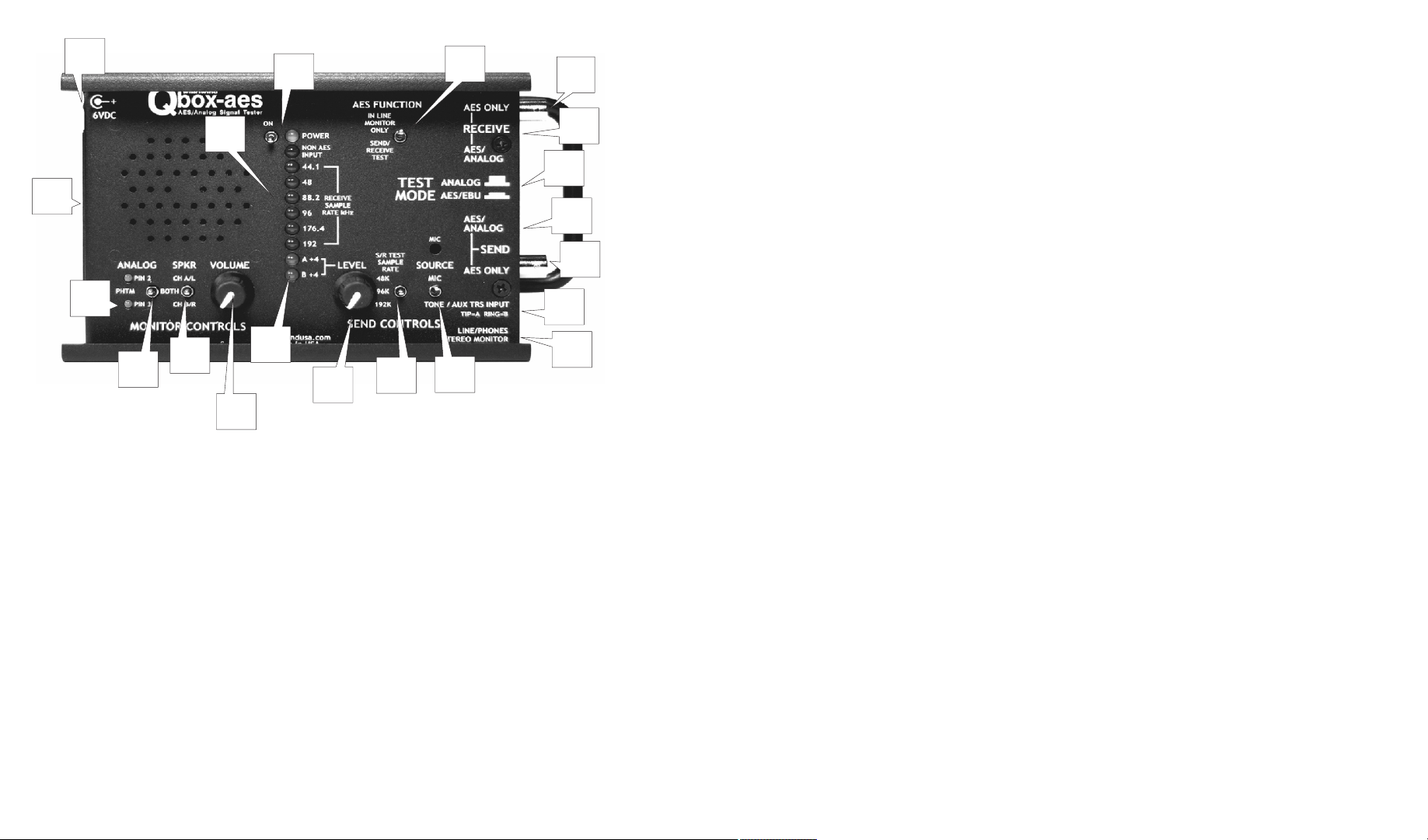
Controls and Functions
1. Test Mode switch selects the type of signal that the Qbox-aes will
analyze. The Out position is for testing analog signals and the In
position is for AES digital types. It is recommended that the operator
turn the unit on and set the proper mode before connecting to the
device being tested.
2. Receive female XLR connector is used as an input for standard
AES-3 digital audio signals over 110 Ohm balanced shielded cable
and balanced or unbalanced analog signals, corresponding to the
position of the Test Mode switch.
3. Receive BNC jack accepts standard unbalanced AES or S/PDIF
digital inputs only over 75 Ohm coaxial cable. This jack is
disconnected in the analog Test Mode. Input levels for both jacks may
be as high as 5 V p-p and as low as 360 mV p-p. Input sample rates
may range from 44.1 kHz to 192 kHz. The two jacks are transformer
isolated and may be used as a loop thru balun for converting from 110
Ohm to 75 Ohm transmission lines in AES test mode.
4
4. AES Function switch chooses the manner of digital
testing to be performed by the Qbox-aes. In Line
3
2
1
20
19
18
17
6. Input Sample Rate LEDs indicate the detected sample rate when locked to a
digital audio input. Only one will be illuminated at a time, except during the
Power-On Self-Test. The Non-AES Input LED illuminates anytime a valid AES
signal is not present.
7. 6VDC external power jack is a 5.5mm x 2.1mm size with the center contact
wired positive and the barrel contact negative. A 6VDC 1000mA plug-in power
supply (model # PS6) with the correct mating connector is supplied with the
unit.
8. Battery Compartment is a slide out drawer that accepts four “AA” cells. New
alkaline batteries will last approx. 6 hours, but battery life reduces to about 1
hour with the speaker at full volume.
9. Analog Pin 2 and Pin 3 green LEDs sense the presence of phantom or
intercom power at the male Send XLR when the unit is in Analog test mode.
Connect to the female XLR to monitor intercom audio.
10. Analog Pin 2 and Pin 3 switch has three positions for listening to balanced
or unbalanced analog signals connected to the Receive XLR. The center
position is for balanced inputs and the Pin 2 and Pin 3 positions provide
individual monitoring of each pin separately.
11. Speaker Monitor A/B switch controls which of the two available digital audio
channels is presented to the speaker for monitoring. In the center position, the
A and B signals are both on and is the proper position when using Analog Test
mode. Changing the switch position in Analog mode will vary the volume but
not the source signal.
Monitor Only mode is used to listen to a digital audio
signal without interrupting its destination. The unit
bridges the data stream for monitoring and passes it
through without alteration. With a digital input signal
present and locked, the digital output sample rate will
mimic the sample rate of the digital input and the
Sample Rate switch has no effect. Send/Receive Test
mode configures the Send and Receive sections to
work independently. The selected test signal is driven
out of the digital Send at the sample rate selected by
the sample rate switch. When an AES input is received
and locked the appropriate Receive Sample Rate LED
will indicate the detected sample rate. The digital
audio is decoded and presented to both the speaker
and the Line/Phones Monitor jack.
5. Power Switch applies power from the external
supply or the batteries and the blue LED illuminates
when the Power switch is ON. The Qbox-aes
performs a self test when first turned on, indicated by
the sample rate LEDs. It is recommended that the unit
complete it's self test before connecting to the device
to be tested. All connections should be removed
before turning the unit off.
12. Monitor Volume adjusts the volume of the built-in speaker and the level of
the signal at the Line/Phones Monitor jack.
13. Green A and B Send LEDS display the amount of analog signal sent to the
A/D converter in AES Test mode and at the Send Xlr in Analog Test mode. They
illuminate when the when the analog input to the A/D converter reaches +4
dBv. This results in a digital output of approximately -12 dBfs. The send level in
Analog mode is -10.4 dBv.
14. Send Level controls the analog level presented to the A/D Converter input.
The mic, tone oscillators, and aux input are affected by this control, typically
adjusted to a level where the +4 green LEDs begin to turn on. With the level
control at full clockwise the digital output is equal to 0.6 dBfs when using the
internal oscillators as a signal source. Maximum analog signal Send output
level is 4.7 dBv.
15. S/R Test Sample Rate switch sets the sample rate of the digital AES stream
output from the Send jacks in Send/Receive Test mode.. It is able to generate
AES-3 or S/PDIF output signals at sample frequencies of 48 kHz, 96 kHz and
192 kHz. In line Monitor mode bypasses any setting of this switch and the
Send sample rate matches that of the input at the Receive jacks.
16. Send Source switch selects the audio source for the Send function. The Mic
position selects the built-in microphone, the Tone/Aux position connects a pair
of tone generators (440 Hz for the left channel, 660 Hz for the right). Plugging
into the Aux TRS Input disconnects the dual oscillators and accepts an external
unbalanced stereo source. In Analog Test mode both oscillator frequencies are
summed together and sent out the balanced Send XLR.
17. Line/Phones Stereo Monitor Jack provides a high-quality output of any
audio source received. Peak output level is +4dB, and the output is capable of
driving headphones from 32 to 100 Ohms impedance. The left channel is
connected to the tip, the right to the ring, and the sleeve to common of the
unbalanced 3.5mm TRS jack. Volume is controlled by the Monitor Volume
control. Connecting to this jack mutes the speaker and is always stereo in AES
Test mode.
18. Aux TRS Input jack allows the operator to connect any analog source to the
unit. The maximum input level is +5 dBv. This is an unbalanced 3.5mm TRS
jack with the left channel connected to the tip, the right to the ring, and the
sleeve to common.
19. Send BNC outputs standard S/PDIF digital audio signals over 75 Ohm
coaxial cable at 5V p-p. In AES Test mode with the unit off, the XLR and BNC
can also be used as a loop thru balun. This jack is not used for Analog Test
mode.
20. Send XLR outputs standard AES-3 digital audio signals over 110 Ohm
balanced shielded cable at 5V p-p in AES Test mode, and with the unit off the
XLR and BNC can be used as a loop thru balun. In Analog Test mode the output
is balanced and the max level is 4.7 dBv with the Send Volume control turned
fully clockwise.
 Loading...