

Page 1
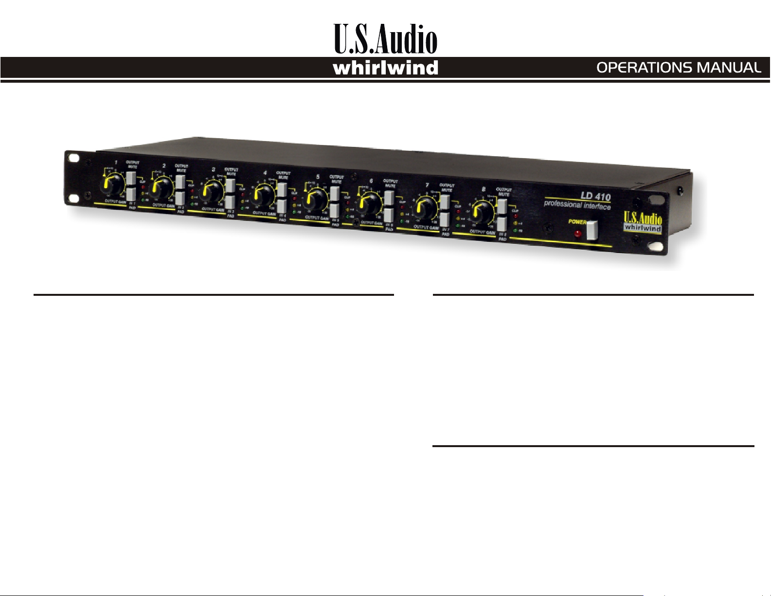
LD410
professional interface
INTRODUCTION
The Whirlwind LD410 Line Driver is the ultimate tool for matching
audio equipment signal levels. The LD410 is both a professional quality,
sonically superior -10 to +4dB to -10dB level converter and a flexible
multichannel distribution amplifier within a single rack space enclosure. Each
of the eight output channels feature gain controls, LED metering and mute
buttons. There are also eight input channels utilizing the highest quality, low
noise preamplifiers with14dB input pads that can be engaged to attenuate high
input signals. The LD410 is factory configured with four channels of 10dB to
+4dB conversion (RCA input jacks to male XLR outputs) and four channels of
+4dB to 10dB level conversion (female XLR inputs to RCA output jacks). An
additional screw terminal block on the rear panel provides balanced signal
connections for those channels with RCA jacks. Assignable signal routing
jumpers inside the LD410 permit the creation of multiple distribution
amplifiers by allowing multiple outputs to receive their signals from a common
input. The LD410 has an internal power supply, which can be set for 115VAC or
230VAC by changing internal jumpers.
UNPACKING
US Audio has made every effort to ensure that your equipment
is received in the same perfect condition it was in when it left the
factory. Please inspect your product for signs of any damage during
shipping and report them to your dealer so that he can present a claim to
the shipper. We recommend that you save your packaging material for
use in the unlikely event that you need to return your equipment for
service.
FEATURES
The LD410 is a one rack space, eight channel, high performance line driver featuring:
· Four channels of +4dB to -10dB level conversion, female XLR to RCA phono.
· Four channels of -10dB to +4dB level conversion, RCA phono to male XLR.
· All eight outputs have -38dB to +38dB variable gain controls.
· Multiple outputs can be assigned to a common input.
· LED metering for -10dB, +4dB, output and input clip indication.
· Mute switches on each output.
· Switchable 14dB pads on each input.
· Screw terminal block allows balanced signal connections to all channels
Page 2

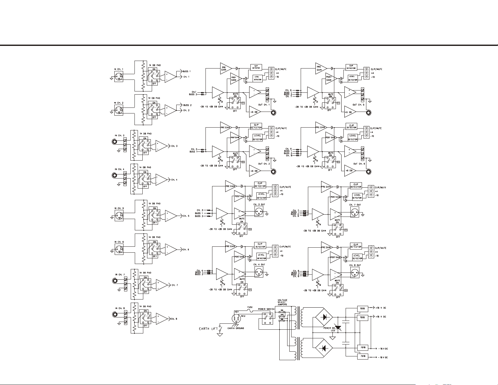
DESCRIPTION OF BLOCK DIAGRAM
The LD410 is a versatile, multipurpose line driver and multi-channel distribution
amplifier. There are eight input channels and eight output channels. Internal signal routing
jumpers configure the connections between the inputs and outputs. There are three types of
connectors providing access to the unit; male and female XLR and Phoenix style screw
terminals for balanced signals and RCA jacks for unbalanced connections.
After the signal has passed through the input connector, the circuitry of each of the input
channel is identical. Inputs 1, 2, 5 and 6 have female XLR balanced connectors. Inputs 3,
4, 7 and 8 have screw terminal connections for balanced signals and RCA jacks for
unbalanced signals. The tip of each RCA jack is wired in parallel to the corresponding
positive screw terminal and the sleeve of the RCA jack is wired in parallel to the minus
screw terminal. This provides a floating ground for unbalanced signals, which may reduce
ground loop hum in some installations. To ground the sleeve of the RCA jack, connect a
small jumper wire between the minus and the ground on the screw terminals of the
corresponding channel.
From the input connector, the signal passes through a switchable 14dB pad. Maximum
input signal level is +22dB and the pad can be inserted to attenuate higher input levels.
The signal then passes to an input buffer circuit and the high quality, low noise, line level
preamp. The output from the preamp is connected to two pin circuit board headers.
Movable jumpers route the signal to the output line drivers.
The output line driver circuits use the signal routing jumpers to select a signal coming
from the input preamps. Signals from inputs 1 and 2 are available to all eight outputs.
Outputs 1 and 2 have two input choices, outputs 3 and 4 have three choices and outputs 4
through 8 have four possible input signal selections. This flexibility allows the
configuration of many different signal distribution schemes.
The standard factory configuration is that of a dual stereo -10dB to +4dB
and +4dB to -10dB level converter. Channels 1, 2, 5 and 6 convert +4dB balanced
signals to -10dB unbalanced. Channels 3, 4, 7 and 8 convert -10dB unbalanced
signals into +4dB balanced ones.
From the routing jumpers, the signal is applied to the gain stage of the output line
driver circuitry and to a clip detector circuit. A front panel gain control provides
up to 38dB of signal gain or attenuation, a range of control sufficient for virtually
any level matching requirement.
Following the gain stage, the signal is delivered to the output buffers, the mute
circuit and the LED level detectors. Each output connector has a separate driver
circuit. This means that on channels 1, 2, 5 and 6, the balanced screw terminal
output and the RCA can be used simultaneously. The mute circuit, activated by a
front panel switch, turns off the signal at the output connector and illuminates the
clip LED to indicate that the output is muted.
The three LED indicators on the front panel monitor signal levels within the
LD410 circuitry. The green -10dB LED and the yellow +4dB LED monitor
output signals after the gain control. The green LED is calibrated to light when
the signal level at the output RCA is at -10dB. The yellow is set to light when the
level at the balanced outputs is at +4dB. The red clip LED monitors the signal
both before and after the output gain stage. This design provides a
troubleshooting tool to help determine whether clipping is being caused by too
much output gain or by excessive input level. If clipping occurs, turn the output
gain down. If the clip LED stays lit, the input signal is too high and the input pad
should be engaged to reduce the level. The red LED is also used to indicate that
the output is muted, it will remain lit when the mute is active.
The power supply for the LD410 is internal and can be set for 230VAC use by
changing internal solder jumpers on the primary of the power transformer.
Page 3
LD410 BLOCK DIAGRAM
Page 4
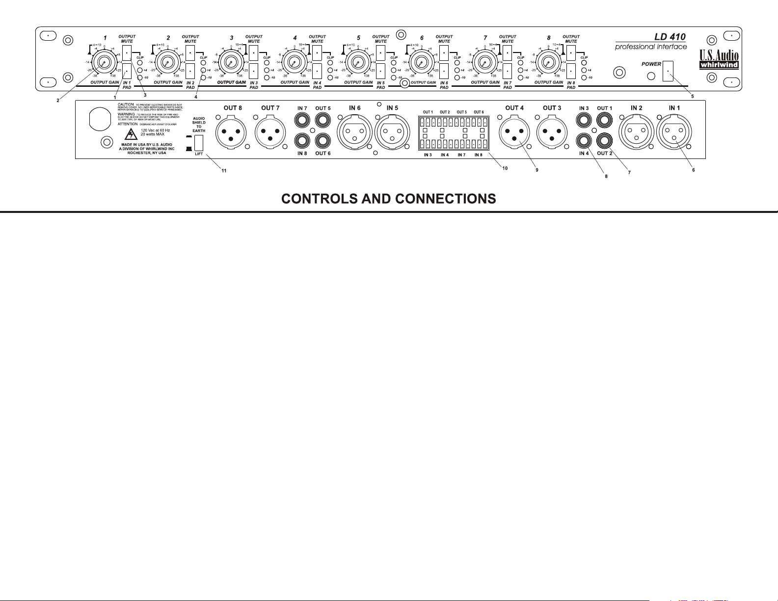
1. Input Pad switch applies a 14dB pad across the input jack when depressed.
2. Gain control varies the signal level at the output jacks. The gain markings around the knob
indicate the amount of gain or attenuation being applied to the signal. The bold mark
designates the normal position for +4dB to -10dB conversion on channels 1, 2, 5 and 6 and
-10dB to +4dB conversion on channels 3, 4, 7 and 8. The "0" gain position is unity gain,
balanced input to balanced output.
3. Output Mute switch turns off the output signal when activated. It also illuminates the clip
LED in a steady state to indicate that the channel is muted.
4. LED Indicators show the level of the signal at the output jacks. Green is set to light when
the output signal is at -10dB and yellow illuminates at +4dB. The red clip LED monitors
the signal level both before and after the output gain control. If the clip LED illuminates,
the output gain can be reduced to determine if the clipping is the result of a high input level
or the amount of output gain. (See “Description of Block Diagram” for details.)
5. Power switch applies power to the unit and the Power LED indicates that the unit is
turned on. There is an internal fuse, which if blown, prevents the power LED from
lighting.
6. Female XLR input jacks on inputs 1, 2, 5, and 6 take balanced line level inputs to the
respective channel's preamp section. The output of each preamp can be assigned (via
internal jumpers) to other output channels in addition to the normal output.
7. RCA output jacks on outputs 1, 2, 5 and 6 deliver unbalanced signals from the line drivers and
are controlled by the output gain pots. The RCA outputs may be used simultaneously with the
balanced outputs (see 10) because they have separate driver circuits.
8. RCA input jacks on inputs 3, 4, 7 and 8 take unbalanced input signals to the respective
channel's preamp section. These jacks are ground floated unbalanced inputs, which parallel
the available balanced inputs (see 10) and can be grounded by connecting a jumper from "G"
to "-" on the screw terminals.
9. Male XLR output jacks on outputs 3, 4, 7 and 8 deliver balanced line level signals from the line
drivers and are controlled by the output gain controls.
10. Screw terminal connections provide balanced signal connections for the channels with RCA
jacks. The RCA jacks on inputs 3, 4, 7 and 8 are connected in parallel across the plus and minus
terminals and can be grounded by connecting a jumper from "G" to "-" on the screw terminals.
The screw terminals on outputs 1, 2, 5 and 6 have separate drivers and can be used
simultaneously with the RCA outputs.
11. Ground lift switch - when depressed, disconnects audio common from earth ground.
12. Internal signal routing jumpers (not shown) allow flexible signal routing from input preamps
to the line driver outputs. Each output is configured at the factory to deliver the signal from the
corresponding input. Changing the jumpers sets up distribution amps, allowing multiple
outputs to deliver the same input signal. (See “Description of Block Diagram”.)
Page 5
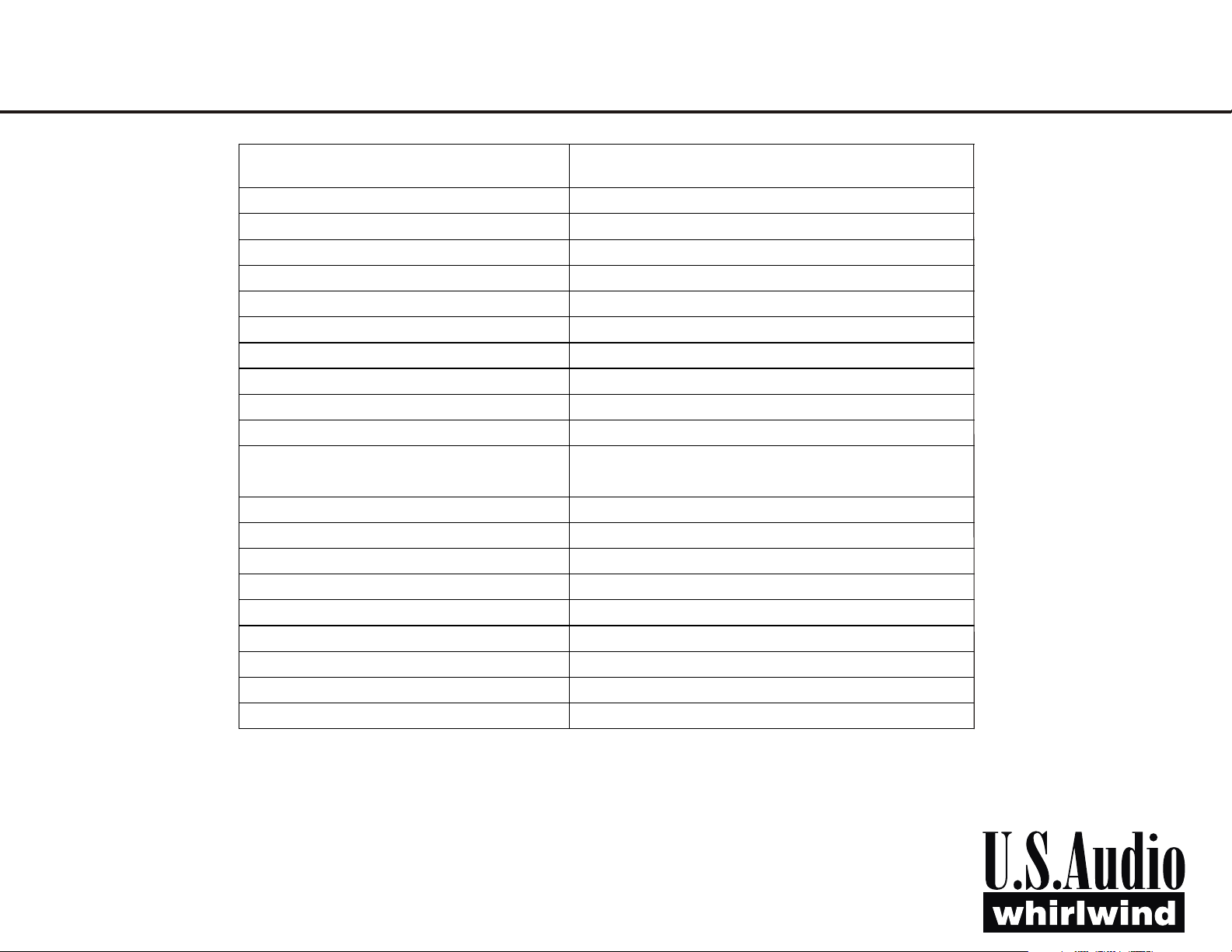
SPECIFICATIONS
Frequency Response
-.6 dBv 20-20K Hz.
-.1 dBv 50-10 K Hz
Total Harmonic Distortion +noise
<.004 % 20-20 K Hz. @ Unity gain
Total Gain
+38 dBv
Range of level pot
-38 to + 38 dBv
Common Mode Rejection of Input
< -72 dBv 20-20 K Hz.
Maximum Input level
+22 dBv
Input Impedance
40 K ohm balanced
Maximum output level
+22 dBv
Output Impedance
200 ohms balanced
Noise at unity gain
-85 dBv
Noise at 14 dBv of gain
-80 dBv
Working signal to noise ratio (at 20
dBv headroom)
> 85 dBv
Isolation between channels
> 85 dBv
Clip LED threshold
+20 dBv
Power consumption
20 Watts Maximum
Power requirements
120 VAC 60 Hz or 230 VAC 50 Hz, factory set
Size
1 Rack unit (19X1.75X6.25”)
Unit Weight
6.5 Pounds
Internal Mains fuse
.2 Amp Slow blow type 3AG
Shipping Weight
8 Pounds
Stereo Separation
>90 dBv 20-20K Hz.
800-733-9473 - 585-663-8820 - Fax: 585-865-8930
99 Ling Road - Rochester, NY 14612
Website: http://www.whirlwindusa.com
Email: [email protected]
 Loading...