

U.S. Audio
whirlwind OPERATIONS MANUAL
Mix 6
STEREO MIXER
INTRODUCTION
Thank you for selecting the US Audio Mix 6. The Mix 6 delivers the ultimate
in sonic performance for the most demanding professional mic and line
mixing applications. Utilizing the Analog Devices 2017 IC, a carefully
wound toroidal power transformer, trUe star grounding, plus many other
design features, the Mix 6 has a working signal to noise ratio (S/N) of 92db
with 22dB headroom at unity gain! At 40dB of gain the Mix 6 holds a working
S/N of 85dB making it ideally suited for production with digital recording
media. The Mix 6 can provide up to 76dB of gain, with a professional quality
signal to noise ratio and still have 10 to 15dB of headroom. Other features
include 2 stereo aux inputs, one of which can be used as a separate monitor
input, a stereo peak limiter, low cut filters and a headphone circuit. \Vith a full
complement of hook-up hardware, the Mix 6 is capable of handling any
configuration of line or mic level signals as well as any combination of
balanced or unbalanced XLR and 1/4” connectors.
UNPACKING
US Audio has made e\'erv effort to ensure that your equipment is received
in the same perfect condition it was in when it left the factory. Please
inspect your product for any signs of damage during shipping and report
them to your dealer so that he can present a claim to the shipper. \Ve
recommend that you save your packaging material for use in the unlikely
event that you need to return your equipment for service.

THEORY OF OPERATION
The US Audio Mix 6 has four mic or line input channels and two stereo aux line inputs. All of the
XLR and 1/4” input and output jacks, except aux 1, are active electronically balanced circuits. The
input sections of channels 1-4 on the Mix 6 use the relatively new Analog Devices 2017 integrated
circuit, which was designed to yield high amounts of gain with the lowest possible noise. This IC,
along with careful component selection, a toroidal power transformer, and true star grounding on a
2 ounce copper double sided circuit board, enable the Mix 6 to achieve a working signal to noise
ratio (S/N) of 92db with 22dB of headroom at unity gain. The Mix 6 holds a working S/N ratio of
85db at 40db of gain and can provide up to 76dB of gain, still maintaining 10 to 15db of headroom.
With the mic/line switch is in the mic position, the 2017 is factory set at 36db of gain by an internal
resistor. This 36db plus the two sections of 20 dB available from each of the channel volumes and
master volume offer a total gain of 76db. For applications which need even more, the Mix 6 can be
ordered or modified to obtain up to 50dB of gain from the 2017 via a simple resistor change.
The output section of the Mix 6 was designed to accommodate any configuration, line or mic level
balanced or unbalanced XLR and balanced or unbalanced 1/4” connectors. Each channel's output
jacks are individually buffered so any combination of the outputs, at any impedance, will not affect
the other outputs. With the Mic/Line output switch in the Mic position, the XLR's output is reduced
by 20db (this switch does not affect the 1/4” jacks). The Mix 6 uses an H-Pad resistor network at
the XLR to maintain the S/N ratio, regardless of the position of the Mic/l.ine switch. For the XLR
outputs, if ground lifting of pin 1 is desired, jumpers JMP 6 and JMP 7 inside the unit can be clipped
off. Then, in Line mode pin 1 of the XLR is completely lifted and in Mic mode the XLR's pin 1 is
ground isolated and referenced to pins 2 and 3. If unbalanced operation is desired from the XLR
outputs, pin 2 is hot, pin 1 is ground, and pin 3 should be left UNCONNECTED.
All the gain controls on the Mix 6 (Channel gain, Aux and Master) have a range of -60 to +20dbm.
With the input and output switches in the Line position and with both the channel and master
volume controls at the same position, unity gain is at the 9 O'clock knob position, 10dB gain at 12
O'clock, and 15dB gain at 3 O'clock. The 60db of attenuation in the off position allows the Mix 6 to
adequately turn off line level signals. Maximum signal level through the Mix 6 at clipping is
+28dBm balanced and +22dBm unbalanced. The sonic figures apply to both the input and the
output and individual clip LEDs are provided which illuminate at -3dB below actual clipping. The
OL (Over Load) circuit senses the signal level in 2 places (input diff amp and after channel gain) to
ensure foolproof visual indication of distortion.
Channels 1-4 have a pan control. The center detented, dual element, audio taper pot provides a
wide range of stereo positioning for the input signal. The center detent allows quick centering of
the signal. Also included on channels 1-4 is a low frequency rolloff switch for elimination of sub
frequencies such as mic handling or wind noise. The cutoff frequency is 120Hz with a 24dB per
octave slope.
LED dB meters provided on the Mix 6 are precisely calibrated at 3dB increments and span a range
of -15 to +l2dBm measured unbalanced at the 1/4” output. The output of the XLR, with the switch
in Line mode, is 6db greater, measured balanced.
The limiter section of the Mix 6 is pre master fader, allowing versatility in selection of output
levels while the peak limiter is active. The limiter is true stereo, with separate detectors for each
side, which engage at 0dB and limit up to 15dB. The left and right LEDs on the front panel
illuminate when the limiter is working and get brighter as limiting increases. With a quick attack
time and moderate ratio the limiter is ideal for open mic situations where unexpected level changes
can occur.
The Mix 6 has a headphone monitoring section consisting of a source select switch, a volume
control, and a 1/4” TRS headphone jack. The headphone circuit is stereo and drives any
headphones with 20 Ohms or greater impedance. The volume control has a gain range of -60 to
+20db to accommodate a wide range of audio levels. The select switch allows listening to either
Aux inputs one and two are true stereo line level inputs. Aux input 1 is via unbalanced RCA jacks.
Aux input 2 is accessed through left and right balanced 1/4” TRS jacks, which can be used
balanced or unbalanced. Aux 2 has a unique main/off switch which routes the input signal to the
left and right stereo busses when activated. This feature allows aux 2 to be disconnected from the
main output and in combination with the headphone main/mon switch, routes the signal to only the
headphones for cueing or monitoring. The Mix 6 aux inputs will interface easily with most all
types of consumer or professional equipment.
the prefader stereo master outputs or the postfader signal coming from the aux 2 inputs.
The Mix 6 utilizes a dual primary toroidal power transformer which is configured with internal
jumpers for 120 V AC 60Hz or 230 VAC 50Hz operation. There is an internal fuse on the hot side of
the AC cord, and the power switch makes and breaks both the hot and neutral legs of the AC cord. A
ground lift switch is provided which can disconnect the audio circuit ground from the AC chassis
ground.

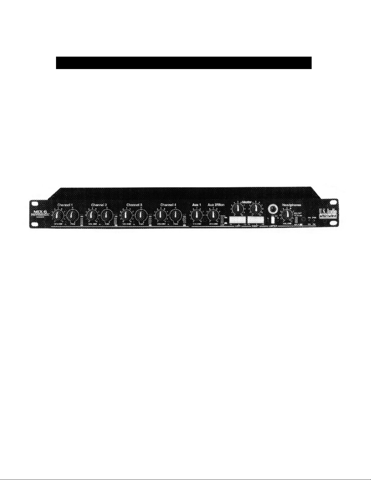
CONTROLS AND CONNECTIONS
1. Channel Volume Pots contr ol input signals over a range of
6OdBm attenuation at full off to 2OdBm of gain at full on.
the “in” position and lifts the signal when “out”. Signal to the headphone switch is
always on.
7. Master Volume Pots determine the amount of signal from the summing amps
that is fed to the output drivers and the meters. These also have a gain range of -60 to
i-2OdBm.
2. Pan Pots are dual pots with center detent, offering over 65dB of stereo isolation
from left to right channel. The center detent allows convenient and accurate setup,
feeding signal equally to both channels.
3. Low frequency Cut Switch for reduction of wind noise, etc. The cutoff
frequency is 120Hz with a 24dB slope.
4. OL (Over Load) LED illuminates when the level is 3dB below distortion. The
clip circuit senses the signal level at the input diff amp and after the channel gain.
5. Aux 1 Input Pot controls the rear panel RCA jacks. Aux I is a stereo unbalanced
circuit feeding the left and right busses. This control has a gain range of -60 to -~20dB.
6. Aux 2 Input Pot controls the rear panel stereo 1/4” TRS balanced jacks through
a gain range of -60 to +20dB. Postfader signal is fed to the headphone select switch
“mon' position allowing aux 2 to become an external input to the headphone circuit.
The main/off switch routes the aux 2 input signal to the left and right stereo busses in
8. LED dB Indicators are precisely calibrated at 3dB increments and span a range
of -15 to +l2dBm measured unbalanced at the 1/4” output. The output of the XLR,
with the switch in Line mode, is 6dB greater.
9. Stereo Peak Limiter is pre master fader and is switchable in or out of the signal
path. Threshold is set at 0dB and limiting up to 15dB is possible. The left and right
LEDs on the front panel illuminate when the limiter is working and get brighter as
limiting increases. Attack time is fast and the ratio is approximately 4:1.
10. Stereo Headphone Circuit consists of a source select switch, a volume
control, a 1/4” TRS headphone jack and will drive any headphones with 20 ohms or
greater impedance. The volume control has a gain range of -60 to +20db. The select
switch feeds either the prefader stereo master signal or the aux 2 postfader signal to
the headphone amplifier.
11. LED Indicators for Phantom Power and Unit Power illuminate
when rear panel switches are activated.

12. Input 1/4 TRS and XLR Jacks are AC coupled through
phantom blocking capacitors with pin 2 being positive wired to tip,
pin 3 being negative wired to ring and pin 1 being common wired to 19. Phantom Power Switch activates 48V DC on channel 1-4 XLR
sleeve. inputs. Status is indicated by the front panel LED. Each of the mic
13. Input MidLine Switch is connected to an active circuit and
turns on 36dB of gain when pushed in to the Mic position. This gain is
applied to both input jacks. 20. Ground Lift Switch connects the audio circuit ground to AC
14. Left and right Unbalanced RCA Jacks for aux 1 input.
15. Left and right Balanced 1/4 TRS Jacks for aux 2 input. AC line are switched and a mains fuse is located on the circuit board
16. Output Mic/Line Switches affect only the XLR output jacks by
inserting a 20dB pad across pins 2 and 3 in the Mic position. 22. Power Cord has a standard 15 amp plug for l2OVAC and has no
17. Output Male XLR Jacks are balanced with pin 2 being
positive, pin 3 being negative and pin 1 being audio ground. For
unbalanced operation use pins I and 2 leaving pin 3
UNCONNECTED. To internally lift pin 1 from common, open the
unit and cut jumper JMP7 for left or JMP6 for right.
18. Output 1/4 TRS Jack delivers the same signal as the XLR but
has a separate driver circuit providing complete isolation. May be
used either balanced with a TRS plug or unbalanced with a TS plug.
Tip is positive, ring is negative and sleeve is audio ground.
inputs is filtered to eliminate crosstalk through the supply rail and
phantom power is isolated from the TRS jacks.
ground and the chassis of the unit, if desired.
21. Power Switch connects AC to the transformer primary and the
front panel LED indicates that the unit is working. Both sides of the
inside the unit.
plug on the Mix 6X 23OVAC models. Black is line, white in neutral
and green is earth.

INPUT
LEVEL
INPUT
MIC/LINE
SWITCH
GAIN
HEADROOM
MAX OUT
SIGNAL
TO NOISE
RATIO
RESIDUAL
NOISE
10 Line 0 12 101 -91
0 Line 0 22 91 -91
0 Line 10 12 92 -82
-10 Line 20 12 82 -72
-10 Line 30 2 82 -62
-20 Line 33 9 72 -59
-20 Mic 36 6 105 -89
-30 Mic 36 16 95 -89
-40 Mic 40 22 85 -85
-40 Mic 50 12 86 -76
-50 Mic 50 22 76 -76
-50 Mic 60 12 76 -66
-60 Mic 60 22 66 -66
-60 Mic 70 12 68 -58

SPECIFICATIONS
Frequency Response
Line mode ± 3dB, 6Hz to 40kHz
-0.4dB @ 20Hz
-.8dB @ 20kHz
Mic mode ± 3dB, 18Hz to 36kHz
-2.5dB @ 20Hz
-1dB @20kHz
Maximum Input Level
Line mode +22 dBm unbalanced
+28 dBm balanced
Mic mode - 14 dBm unbalanced
+28 dBm balanced
Aux 1& 2 +22 dBm unbalanced
+28 dBm balanced
Input Impedance 4k Ohm
Aux 2 Input Impedance 4k Ohm
Maximum Output Level
Balanced +28dBm
Unbalanced +22dBm
Output Impedance XLRs
Line mode 100 Ohms
Mic mode 200 Ohms
LED Clip Threshold +19dBm unbalanced
+25dBm balanced
THD+N (Total Harmonic Distortion + Noise)
.005% @ 1kHz
.02% 20Hz to 20kHz
Phantom Power + 48 Volts DC
Power Consumption .27 Amps Max AC @ 120 VAC
.27 Amps Max AC @ 230 VAC
AC Dropout Voltage +103 VAC @ 120VAC Nominal
+203 VAC @ 23OVAC Nominal
Internal Mains Fuse .25 Amps Slo-Blo 3AG
Size (Single space standard E.I.A. Spec)
19.0” (482.6mm) Width
6.0” (152.4mm) Depth
1.75” (44.45mm) Height
Shipping Weight 9 lbs (4.08kg)
Unit Weight 7 lbs (3.18kg)
Output Impedance TRS
Unbalanced 60 Ohms
Balanced 120 Ohms
Rise Time 8.6uSec
Stereo Separation >65dBm
Attenuation Of Llne/Mic 20dBm
Output Switch
Isolation Between 1/4” and >100dBm
XLR Outputs
C.M.R. (Common Mode > 55dBm @ 60Hz
Rejection) of Input
whirlwind 99 Ling Road Rochester NY 14612 800 733-9473·· ·
 Loading...