

Page 1
OPERATIONS MANUAL
DA2M Product Specifications
Frequency Response Line: +/- .5 dB 20-20 kHz
Mic: +/- .65 dB 20-20 kHz
Total Harmonic Distortion +noise < .003 % at 1 kHz
Equivalent Input Noise 121 dB
Total Gain 74.7 dBV
Gain of Microphone/Line Switch 29 dBV
Gain of Input Trim 28.7 dBV
Gain of Channel Volume 17.0 dBV
Range of level pot Trim –40.8 to +28.7 dBV
Channel: -61 to +17 dBV
Common Mode Rejection of Input Line: -80.9 dB at 60 Hz, unity gain
Mic: -68 dB at 60 Hz, 40 dBV of gain
Maximum Input level Line: +22 dBV
Mic: -7 dBV
Input Impedance Line: 40 K Ohms
Mic: 1.5 K Ohms
Maximum output level +27.6 dBV
Output drive power +22 dBV into 600 Ohms
Output Impedance 100 Ohms
Minimum impedance of headphones 8 Ohms
Noise at unity gain -92.4 dBV Line mode
Noise at 40 dBV of gain Mic mode -80.4 dBV
Working signal to noise ratio (at 20 dBV
headroom)
Line: 114.6 dB at unity
Mic: 87.4 dB at 40 dBV of gain
Isolation between input channels Line at unity:
112 dBV at 1 kHz
98 dBV at 20 kHz
Mic at 40 dBV of gain:
90 dBV at 1 kHz
75 dBV at 20 kHz
Clip LED threshold
LED Headroom
Red 1 dBV
Yellow 12 dBV
Green 1 24 dBV
Green 2 36 dBV
Phantom Power 48 Volts DC
High pass filter 3 dB at 120 Hz
24 dB per octave slope
Output isolation between channels 102 dBV at 1 kHz
95 dBV at 20 kHz
Max Output of Headphones +12 dBm at 47 Ohms
+7 dBm at 23.5 Ohms
Power consumption
Condition Amps AC
Idle .09
Full clean .195
Max. .30
Size 1 RU
Internal Mains fuse .5 amp slow blow type 3ag
AC dropout voltage 105 VAC 60 Hz
Power requirements 120 VAC 60 Hz
Internal jumpers for 230 VAC 50 operation 40 Watts
Max.
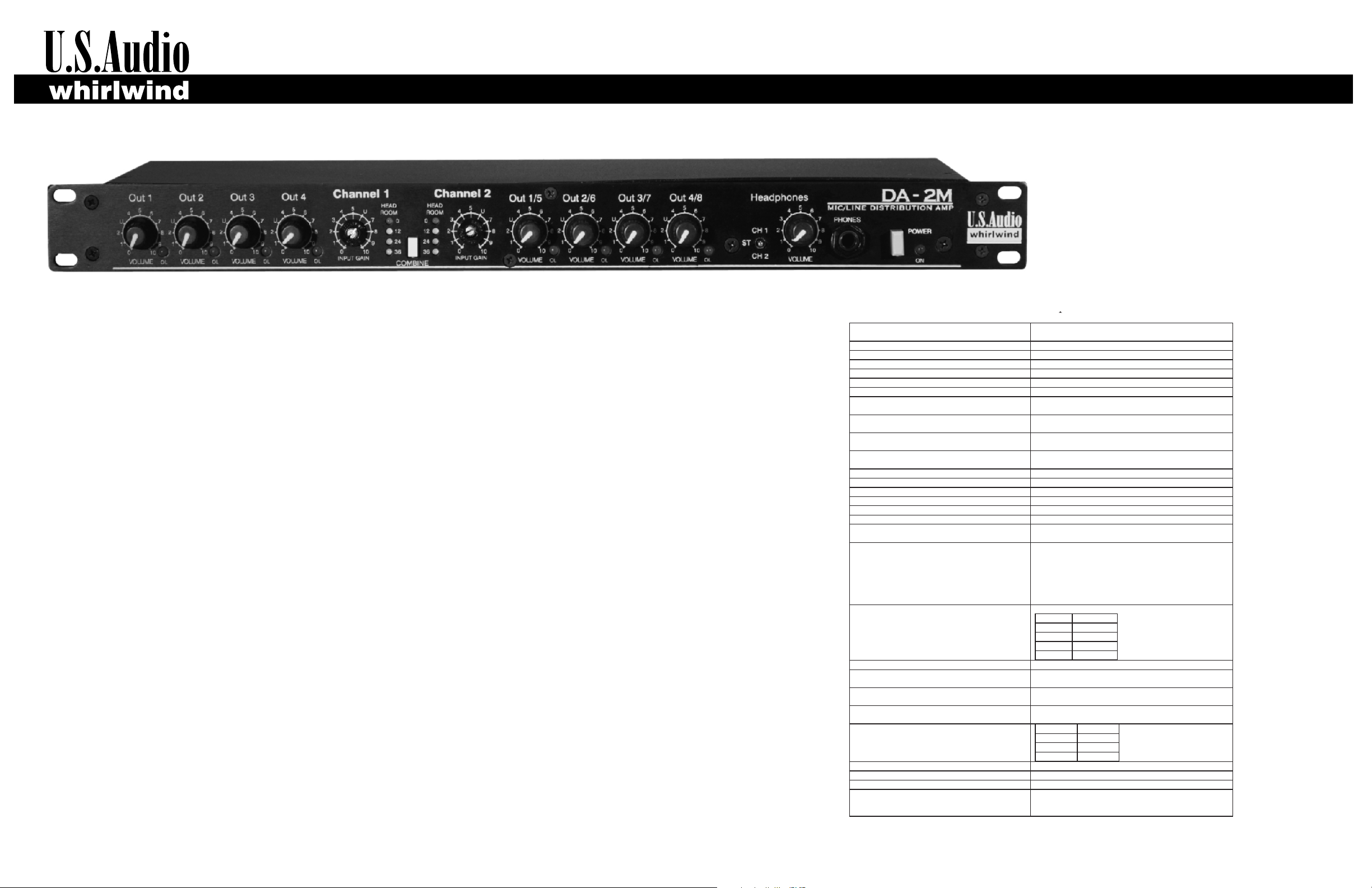
DA-2M
DISTRIBUTION AMPLIFIER
INTRODUCTION
SPECIFICATIONS
Thank you for selecting the US Audio DA-2M. a
analog audio distribution amplifier .
electronically balanced XLR line level outputs with individual volume controls and clip indicators. The
audio performance is of the highest quality, making it an excellent value. Great care was taken in the
design so that the DA-2M can fulfill any distribution requirement, from broadcast audio feeds to
loudspeaker audio input distribution.
Inputs feature Neutrik combo 1/4” TRS/XLR connectors, mic/line level input switches, variable input
gain controls, low cut switches for reducing low frequency rumble or wind noise, four segment
headroom indicators and 48 V phantom power that is applied to the XLR in mic mode and turned off
when the input is used in line mode.
The front panel COMBINE switch converts the DA-2M from two 1X4 distribution amps to a 2x8
distribution amp with the two inputs combining to feed all eight outputs. This provides the capability of
having both a line and a mic input simultaneously.
A headphone circuit allows signal monitoring of each input in mono or listening to both input channels
in a stereo mode.
UNPACKING
U.S. Audio has made every effort to ensure that your equipment is received in the same perfect
condition it was when it left the factory. Please inspect your product for any signs of damage during
shipping and report them to your dealer so that a claim can be made to the shipper. We recommend
that you save your packing material for use in the unlikely event that you need to return your
equipment for service.
which accepts either mic or line level inputs There are eight
The DA-2M is professional quality two channel
Page 2

CONTROLS AND CONNECTIONS
THEORY OF OPERATION
The Whirlwind DA-2M is a 1 RU Distribution Amplifier (DA) with 2
mic/line inputs and 8 outputs. Using the same technology as in
high-end mixing consoles, the DA-2M boasts low noise and
distortion, suitable for the most demanding of professional audio
applications. The expanded feature set allows this unit to be used
in numerous applications.
The DA-2M can be used in stereo or a 2 channel application as
two sets of 1 in (mic or line) to 4 out DAs (stereo, with 4 zones), or
in a mono application as 1 set of 2 inputs combined (mic and/or
line) to 8 outs (mono). The 2 inputs are switchable for either mic or
line level applications. The mic preamp is set for a fixed 29 dB of
gain when the mic/line switch is in the mic position. A trim control
after the preamp adds another 28 dB of gain, and then each
output level control adds another 17 dB of gain. Total gain is 74
dBV, allowing one to drive power amplifiers to full power with all
microphones.
The input connector is a Neutrik Combo, which is female XLR and
¼ inch Tip Ring Sleeve jack. Either connector can be used in mic
or line mode. When the DA-2M's inputs are in mic mode 48 Volt
phantom power will be present on the XLR input connector (not
present on the TRS). A low cut filter can be activated on both XLR
or TRS inputs with a switch. The low cut uses a steep 24 dB per
octave 4 pole filter set at 120 Hertz which will reduce wind noise,
stage vibrations etc. In line mode, the DA-2M's 40 kOhm input
impedance allows the user to parallel many DA-2M inputs
together to generate numerous buffered outputs.
The headroom LEDs on each of the inputs provide quick visual
confirmation of input level and headroom. Designed with an
extreme amount of headroom (the DA-2M uses a bipolar 18 VDC
supplies) the DA-2M can drive up to 27 dBV without distortion
down balanced lines. In a typical mic application, the user would
set the input trim controls so that the 24 dB headroom light is
illuminated about 50% of the time. With more compressed line
level audio, 12 dB of headroom usually is sufficient.
The Headphone section of the DA-2M uses a 3-position switch
allowing for stereo listening or mono listening of either input. In
the non combine mode (stereo or 2 channel) with the headphone
select switch in the middle position, input 1 will be on the left
earpiece and input 2 with be on the right earpiece. With the
headphone select switch in the channel 1 position, channel 1 will
be in both earpieces. With the headphone select switch in the
channel 2 position, channel 2 will be in both earpieces. The
volume control and the headphone amps are designed so a wide
range of headphones of varying impedances may be used.
The 8 balanced outputs of the DA-2M are male XLR with
individual level controls, clip LEDs, and ground lift switches. The
level controls span a range of -60 to +18 dBV of gain. With the
level control able to reduce signal 60 dB, this is sufficient to mute
audio in most applications. When ground loop hum occurs, lifting
the ground at the DA-2M's outputs can help break the loop. The
clip LED on each channel visually shows the user that levels are
too great and need to be turned down.
When using the outputs to drive an unbalanced input the male
XLRs can be wired 2 ways. The standard configuration is using
pin 2 hot, pin 1 as ground and no connection on pin 3. The output
ground switch for this channel must be ON in this setup. The
second is called “quasi balanced” and is used primarily when
ground loops are an issue. Wire pin 2 to hot and pin 3 to ground of
the unbalanced input, leaving pin 1 unconnected.
An earth to audio ground lift is also supplied on the back panel of
the DA-2M. This switch separates the earth ground of the power
cord (which is always connected to the chassis) from the audio
ground. This ground can also be used to break audio ground
loops, however breaking them with the individual channel ground
switches is a better approach. When in high Radio Frequency
Interference situations, it is suggested to keep audio ground
connected to chassis ground.
Housed in a compact 1 RU enclosure the DA-2M uses a dual
primary toroidal power transformer. Internal jumpers can be
changed to operate the DA-2M at 230 VAC 50 Hertz.
1. Output Volume Pots control the level at the corresponding
rear panel output XLR. Each of the controls has a gain range of 60 dB attenuation at full off to +18 dB of gain at full on.
2. Individual Clip LEDs on all 8 outputs indicate signal overload
conditions within the circuitry. The red clip LEDs illuminate at the
clipping point of the unit (+27 dBV).
3. Input Gain Controls for each channel adjust the input signal to
optimize to drive level to the outputs. These controls operate
through a range of -40 dB to +30 dB and are shipped as
screwdriver adjustable to deter unauthorized operation. If knob
actuation is desired, remove the black bushings and install the
included knobs as follows. Carefully pry the edge of the bushings
away from the front panel and depress the plastic fingers that
hold them in place. The fingers are located behind the printed
areas on the face of the bushing. Rotate the control fully
counterclockwise, align the knob’s pointer with the scale and
push it onto the shaft. If repositioning is required, the knob insert
must be removed separately by grabbing the rectangular top with
pliers and pulling it off. Reinstall the insert into the knob by
aligning the ridge on the insert with the groove inside the knob
behind the pointer.
4. Headroom Indicator LEDs on each of the input channels
indicate the remaining headroom of the signal being applied to
the output drive circuitry. The two green lights and the yellow
in dicat e le vel below cli pping (-3 6,-24 , an d -1 2 dB
respectively)and the red LED illuminates at 1 dB below actual
clipping.
5. Combine switch converts the
distribution amps to a 2x8 distribution amp with the two inputs
combining to feed all eight outputs.
are actively mono-summed, either input may be used to feed the
eight outputs. The mono-sum feature allows the DA-2M to
properly combine left and right stereo signals into a mono feed
and also using both
input simultaneously.
6. Channel 1/ST/2 Select switch determines the input signal
that is fed to the headphone circuit for monitoring. Channel 1 or 2
selections are fed to both left and right as mono and the center ST
position feeds Ch. 1 to the left and Ch. 2 to the right.
provides the capability of a line and a mic
DA-2M from two 1X4
In this mode the two inputs
7. Headphone Circuit monitors the signals coming into the DA2M inputs. It separately drives both earpieces in stereo
headphones having an impedance 8 Ohms or greater. The
volume control has a gain range of -60 to +18 dB to accommodate
a wide range of audio levels. The jack is a standard 1/4” TRS type.
8. Power Switch connects AC to the transformer primary and the
LED indicates that the unit is working. Both sides of the AC line
are switched and a mains fuse is located on the circuit board
inside the unit.
9. Output XLRs on the DA-2M are actively balanced with each
output driven by its own individual driver circuit providing channel
to channel isolation greater than 102 dBV. The outputs are wired
pin 2 positive, pin 3 negative and are RF bypassed with
capacitors for rejection of RF signals on output lines.
10.Output Ground Switches are provided to connect Pin 1
from each output XLR to the common audio ground bus. The dip
switches are numbered 1-4 and correspond with the same
numbered male XLR. In the down (off) position the Pin 1 of each
output is lifted.
11. Low Cut Switch activates a 24 dB per octave filter set at 120
Hertz which will reduce wind noise, stage vibrations etc. The low
cut filter is applied to both XLR and TRS inputs in either mic or line
input mode.
12. Input connectors are combination female XLR and
balanced ¼ inch TRS jacks. Either type can be used in mic or line
mode. In mic mode 48 Volt phantom power will be present on the
XLR only (not on the TRS). In line mode, the 40 kOhm input
impedance allows the user to parallel many DA2M inputs
together.
13. Mic/Line Switches insert the microphone preamps into the
circuit when required for mic level input applications. Each mic
preamp is set for a fixed 29 dB of gain in the mic position.
14. Audio Shield to Earth Switch separates the earth ground of
the power cord (which is always connected to the chassis) from
the audio ground. When in high Radio Frequency Interference
situations, it is suggested to keep audio ground connected to
chassis ground.
15 . Power Cord has a standard 15 Amp plug for the DA2M 120
VAC model and has no plug on the DA2MX 230 VAC model.
Black is line, white is neutral and green is earth. The mains fuse is
internal.
 Loading...