

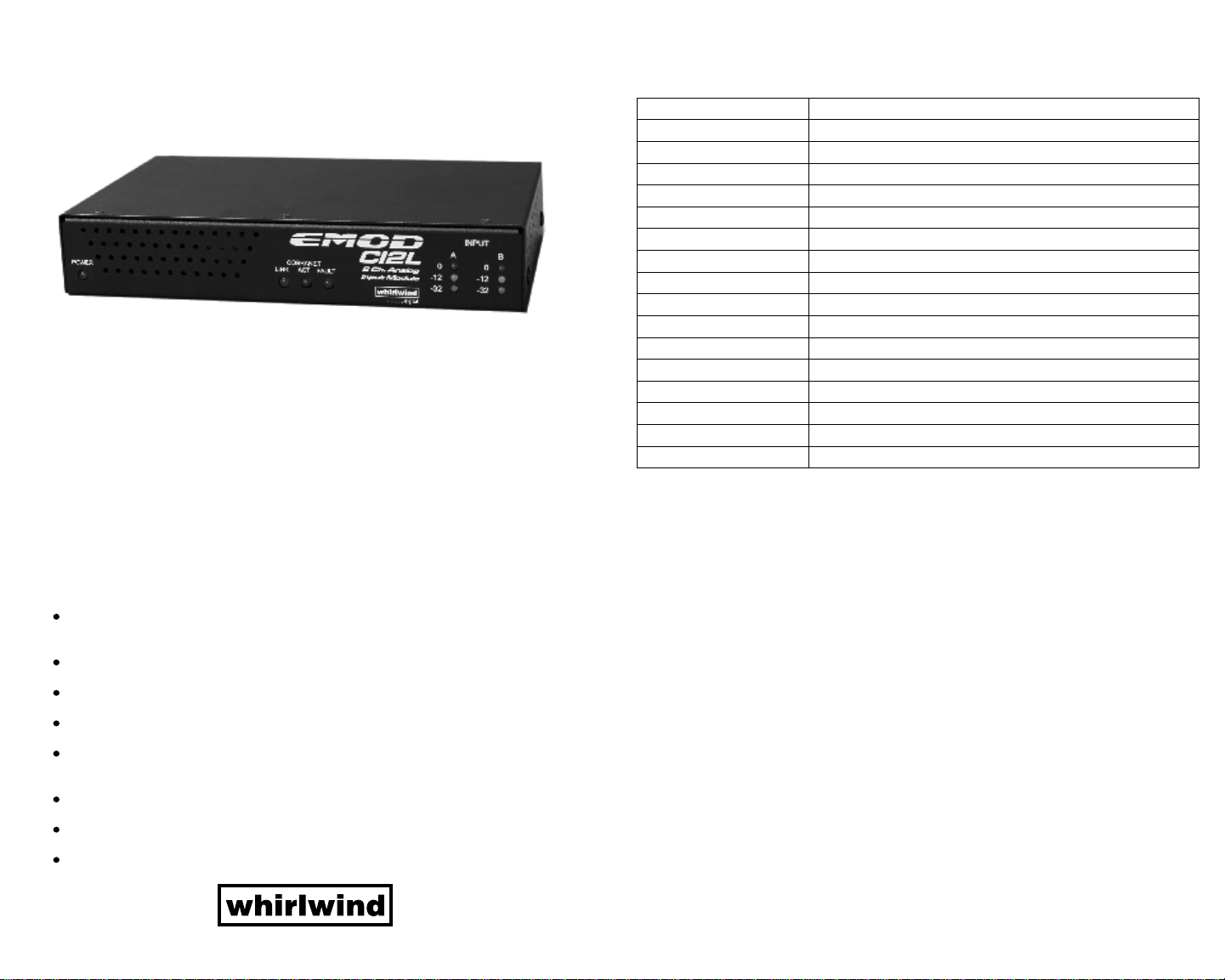
EMOD
CI2L
2 Ch.Analog
Input Module
The CI2L is Whirlwind's 2-channel CobraNet line level input module. Use it to convert
line level analog audio into professional quality digital audio for distribution over
CobraNet digital networks. The CI2L can be temporarily or permanently connected to
the CobraNet network, anywhere network access and AC power are available.
Connect any line level source such as stereo mixer outputs, computer sound card
outputs, or media player outputs and instantly send them throughout the CobraNet
digital audio network.
Frequency Response
Total Harmonic Distortion +noise
Dynamic Range
Stereo Separation
Total Gain
Range of level pot
Common Mode Rejection of Input
Maximum Input level
Input Impedance
Noise at various gains
Input LED threshold
Thermals
Power consumption
Power requirements
Size
Unit Weight
Internal Mains fuse
Specifications for Whirlwind CI2L
± .25 dBv 20-20 kHz at unity gain
< .0022% 20-20 kHz at unity gain
110 dBv at unity gain, 97 dBv at 20 dBv of gain, 101 dBv at 20 dBv of attenuation
< -98 dBv at 20 kHz <-112 dBv at 1 kHz
36 dBv
-36 dBv to + 36 dBv
70 dBv 20-20 kHz
+20 dBv
20k Ohms balanced
-100 dBv at unity, -87 dBv at 20 dBv of gain, -101 dBv at 20 dBv of attenuation
0 dBfs, -12 dBfs, and –36 dBfs
Convection cooled, 5 to 30°C operating range
13.3 Watts idle, 17 Watts max
85-264 VAC, 50 or 60 Hz
8 1/2” x 5/8” x 6” (WxHxD)
3 lbs.
Internal self resetting .37 Amp trip current .16 Amps hold current
Setup and operation are simple and easy. Just set the bundle select wheels to the
desired transmit bundle number, and set the bitwidth/latency selector to match the
bitwidth and latency of the receiving device. Then apply the two channels of audio and
adjust the input level as necessary, ensuring that the level is below the 0dB clipping
level.
FEATURES
Uses CobraNet networking protocol compatible with all other CobraNet devices
from over 40 manufacturers.
Transmits 20 or 24 bit word length.
Transmits 5.33 ms, 2.66 ms or 1.33 ms latencies.
Inputs can be assigned to multiple channels within the transmit bundle.
Input level control can provide 36 dB of gain or attenuation to the analog input
signal.
Front panel LED meters indicate analog signal level.
Integrated universal power supply for 100-250 VAC, 50/60 Hz operation
Integral mounting bracket provides for secure vertical or horizontal orientation or
mounting to a rack shelf.
MADE IN USA
All specifications subject to change without notice
WARRANTY
This product is guaranteed to be free from defects in materials and workmanship to the
original purchaser for a period of 5 years from the date of purchase. Should service be
required, return the unit postage prepaid along with the original sales receipt to:
Whirlwind
Attention - Repair
99 Ling Road
Rochester, New York 14612
The warranty on this product shall not apply to defects or damage resulting from abuse, abnormal use or
from repairs or modifications performed by anyone other than Whirlwind. If it is determined a
manufacturing defect has occurred, Whirlwind will repair or replace the unit at our option and pay the
postage back to you.
99 Ling Road - Rochester, NY 14612
800-733-9473 / 585-663-8820 Fax: 585-865-8930
Website: http://www.whirlwindusa.com
Email: sales@whirlwindusa.com
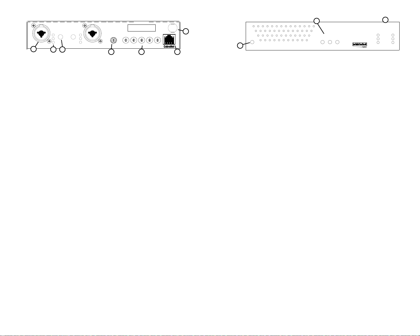
A=Ch 1
A=Odd Ch
B=Ch 2
B=Even Ch
A= All Ch
1 20:5
7 20:5
D 24:5
2 20:2
8 20:2
E 24:2
3 20:1
9 20:1
A B
0
-12
-36
1
1
1.
Combination XLR and ¼” TRS inputs A and B accept balanced or unbalanced analog audio
2
2
0
-12
-36
Model:CI2L WHIRLWIND USA www.whirlwindusa.com
3
F 24:1
4 24:5
A 24:5
5 24:2
B 24:2
6 24:1
C 24:1
COBRANET BUNDLE SELECT
3
3
2
2
4
4
1
1
5
5
0
0
6
6
9
9
7
7
8
8
4
85-264VAC
50/60Hz
15W
3
3
3
2
2
2
4
4
4
1
1
1
5
5
0
9
7
8
5
0
0
6
6
6
9
9
7
7
8
8
5
7
6
at line levels.
Three position LED meters monitor the analog signal at the inputs of the analog to digital
2.
converters after the input level controls. The green LED illuminates at -36 dBfs, the yellow
at -12 dBfs and the red at the clipping point of the analog to digital converter.
Input Controls adjust the level of the analog input signal being applied to the analog to
3.
digital converters. 36 dB of gain or attenuation allows optimization of the analog signal to
minimize noise at the converters. Adjust the signal so that peaks do not light the red 0 dBfs
LED.
Bitwidth/Latency Selector matches the audio bitwidth and latency transmitted by the CI2L to
4.
that of the receiving CobraNet device. Individual CobraNet devices must have the same
bitwidth and latency to communicate with each other properly. The transmit setting must be
acceptable to the device set to receive that bundle. Many receive devices have an
autodetect feature that will match the bitwidth and latency to that of the transmitter. The
CI2L uses a 16 position selector for choosing 20 or 24 bit word length and 5.33ms, 2.66 ms
or 1.33 ms latencies. In addition, the CI2L can assign its two analog input signals to
multiple channels within the CobraNet bundle. Positions 1-6 assign Input 1 to Bundle
channel 1 and Input 2 to Bundle channel 2 at the six choices for bitwidth and latency.
Positions 7-C assign Input 1 to Bundle channels 1,3,5,7 and Input 2 to Bundle channels
2,4,6,and 8. Positions D-F assign Input 1 to all channels in the Bundle at 24 bit word length
and 5.33 ms, 2.66 ms or 1.33 ms latencies.
In 24 bit word length and 5.33 ms latency mode, a special case exists; there are a
maximum of seven audio channels that can be packaged into a single bundle at this
setting. The CI2L handles this exception by only transmitting seven channels and truncating
channel 8. (Encoder positions A and D)
0
-12
-36
8
INPUT
A B
0
-12
-36
9
EMOD
POWER
LINK
COBRANET
ACT
10
7.
Power cord is a standard US 15 A 3 wire connection. The power supply is internationally
CI2L
2 Ch. Analog
FAULT
Input Module
universal by changing the plug at the end of the cord. Black or Brown = Line; White or Blue
= Neutral; Green or GrnYel = Ground.
Three position LED meters are the same as the meters on the rear panel. The green LED
8.
illuminates at -36 dBfs, the yellow at -12 dBfs and the red at 0 dBfs, the clipping point of the
analog to digital converter.
9.
CobraNet LINK, ACT, and FAULT LEDs indicate the status of the CobraNet network
connection;
LINK LED illuminates only when the Ethernet cable is connected to a network with other
CobraNet devices.
ACT (activity) LED is on only when there is a match between the bitwidth/latency and
bundle settings of the CI2L and those of the receiving device.
FAULT LED is used to blink a numeric code to the user with a series of blinks followed by a
pause. The number of blinks indicate the following:
1. Mismatched format or bundle settings
2. Not used on CI2L
3. Invalid bundle number selected (greater than bundle # 65279)
4. Ethernet cable disconnected or no other CobraNet devices on network.
5. CobraNet can not communicate with DSP in the CI2L.
6. This code blinks once on power up and whenever an encoder setting change is
detected, to warn the user that persistence is enabled through CobraNet Discovery v3.4.4
and that changing the encoders from 00000 will defeat Disco control at the next power
cycle. Persistence enabled means that the unit will remember its last settings through
power cycling.
10.
Power LED illuminates when AC power is applied to the unit and the unit is operating.
CobraNet Bundle Select switches are used to select the bundle number to be transmitted
5.
by the CI2L. All 65,279 CobraNet bundles are directly accessible from the encoders.
Bundles 1-255 are Multicast bundles and 256-65,279 are Unicast. The leftmost encoder
also has 3 special functions. With the encoder in the 7xxxx position, the front three status
LEDs (LINK, ACT, FAULT) and the audio LEDs, both front and rear, will flash a code for the
software version in the CI2L. The LEDs will blink the number of the software version with a
long pause between the series of blinks; e.g., four flashes followed by a long pause equals
version four. Should the CI2L ever need to be rebooted, the 8xxxx position of the encoder
will cycle a reset of the unit every two seconds. Unplugging and reconnecting the power
cord will also reset the CI2L. The 9xxxx position of the encoder is a self test for all the LEDs
except the power LED. Setting all switches to 0 allows remote setting of bundle
parameters through the network with CobraNet Discovery software v3.4.4.
6.
CobraNet Jack connects the CI2L to the Ethernet switch carrying the CobraNet network. A
green LED indicates network link and a yellow LED indicates data activity. These are
duplicated by two green LEDs on the front panel along with a red Fault LED indicator.
CobraNet Parameter Control through Discovery v3.4.4.
Setting all the Bundle Select Switches to 00000 allows remote setting of CobraNet
parameters through the network with CobraNet Discovery software, v3.4.4 available at
www.cirrus.com/cobranetsoftware. Some of the parameters that can be controlled on the
CI2L include bundle number, number of channels in the bundles, digital word length,
latency and persistence.
These parameters are unlike the selections made with the encoders. Bundle numbers and
bitwidth:latency selections made with the switches are hard coded and remembered when
the power to the CI2l is cycled. Settings made through Disco are volatile and forgotten on
a power cycle, unless persistence is turned on and Bundle Select Switches are set to 0.
There are also four transmitters available through Disco instead of just the one through the
encoders.
Disco will temporarily override encoder settings on a CI2L. These settings will not be
remembered on power cycling regardless of the persistence setting in Disco.
 Loading...