

Whirlpool YMER8880BS0, YMER8850DS1, YMER8880BB0, YMER8800FZ0, YMER8800FB1 Installation Guide
...
INSTALLATIONINSTRUCTIONS
30" (76.0 CM) FREESTANDING ELECTRICRANGES
INSTRUCTIONSD'INSTALLATIONDESCUISINIERES
ELECTRIQUESAUTOPORTANTESDE30" (76,0 CM)
Tableof Contents/Table des mati@res
RANGE SAFETY ........................................................................................... 2
INSTALLATION REQUIREMENTS ............................................................. 3
Tools and Parts ......................................................................................... 3
Location Requirements ............................................................................. 3
Electrical Requirements - Canada Only ................................................... 4
INSTALLATION INSTRUCTIONS ............................................................... 4
Unpack Range .......................................................................................... 4
Install Anti-Tip Bracket .............................................................................. 5
Verify Anti-Tip Bracket Is Installed and Engaged ..................................... 6
Level Range .............................................................................................. 6
Warming Drawer or Premium Storage Drawer ......................................... 7
Storage Drawer ......................................................................................... 7
Oven Door ................................................................................................. 7
Complete Installation ................................................................................ 8
Moving the Range ..................................................................................... 8
SECURITE DE LA CUISINIERE .................................................................. g
EXIGENCES D'INSTALLATION ................................................................ 10
Outillage et pieces .................................................................................. 10
Exigences d'emplacement ..................................................................... 10
Specifications electriques ....................................................................... 11
INSTRUCTIONS [:)'INSTALLATION ......................................................... 12
Deballage de la cuisiniere ....................................................................... 12
Installation de la bride antibasculement ................................................. 12
Verifier que la bride antibasculement est bien installee et engagee ...... 13
Reglage de I'aplomb de la cuisiniere ..................................................... 14
Tiroir-rechaud ou tiroir de remisage de qualite superieure .................... 14
Tiroir de remisage ................................................................................... 15
Porte du four ........................................................................................... 15
Achever I'installation ............................................................................... 16
Deplacement de la cuisiniere ................................................................. 16
iMPORTANT:
Save for local electrical inspector's use.
iMPORTANT :
_, conserver pour consultation par I'inspecteur local des installations 61ectriques.
W10403812C
RANGE SAFETY
Your safety and the safety of others are very important.
We have provided many important safety messages in this manual and on your appliance. Always read and obey all safety
messages.
This is the safety alert symbol.
This symbol alerts you to potential hazards that can kill or hurt you and others.
All safety messages will follow the safety alert symbol and either the word "DANGER" or "WARNING."
These words mean:
You can be killed or seriously injured if you don't immediately
follow instructions.
You can be killed or seriously injured if you don't follow
instructions.
All safety messages will tell you what the potential hazard is, tell you how to reduce the chance of injury, and tell you what can
happen if the instructions are not followed.
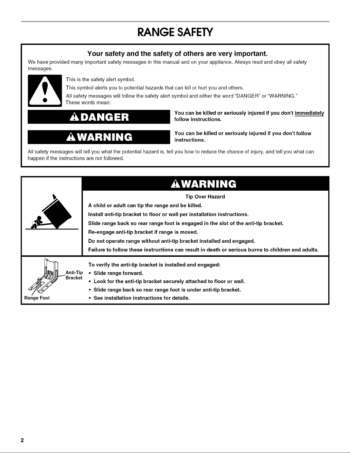
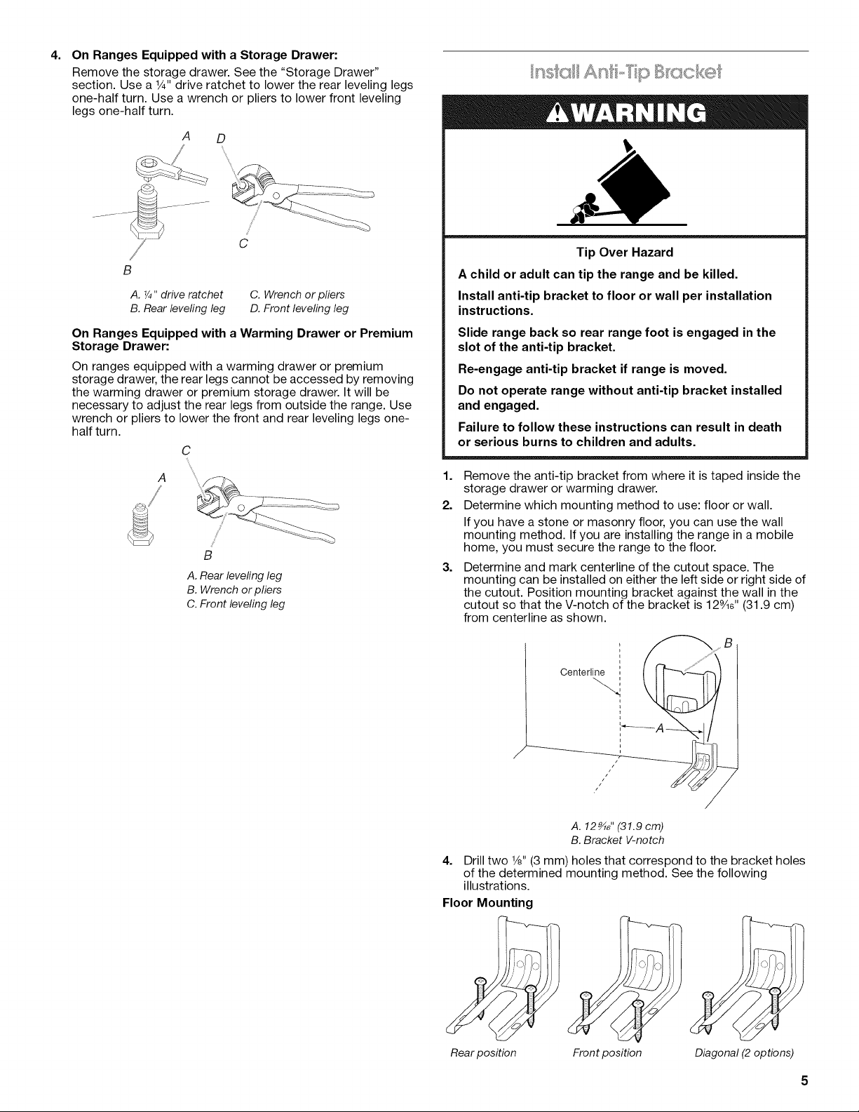
Tip Over Hazard
A child or adult can tip the range and be killed.
Install anti-tip bracket to floor or wall per installation instructions.
Slide range back so rear range foot is engaged in the slot of the anti-tip bracket.
Re-engage anti-tip bracket if range is moved.
Do not operate range without anti-tip bracket installed and engaged.
Failure to follow these instructions can result in death or serious burns to children and adults.
Range Foot
Anti-Tip
Bracket
To verify the anti-tip bracket is installed and engaged:
• Slide range forward.
• Look for the anti-tip bracket securely attached to floor or wall.
• Slide range back so rear range foot is under anti-tip bracket.
• See installation instructions for details.
2
INSTALLATIONREQUIREMENTS
Gather the required tools and parts before starting installation.
Read and follow the instructions provided with any tools listed
here.
Tools needed
• Tape measure
• Flat-blade screwdriver
• Phillips screwdriver
• Level
• Hammer
• Hand or electric drill
• Wrench or pliers
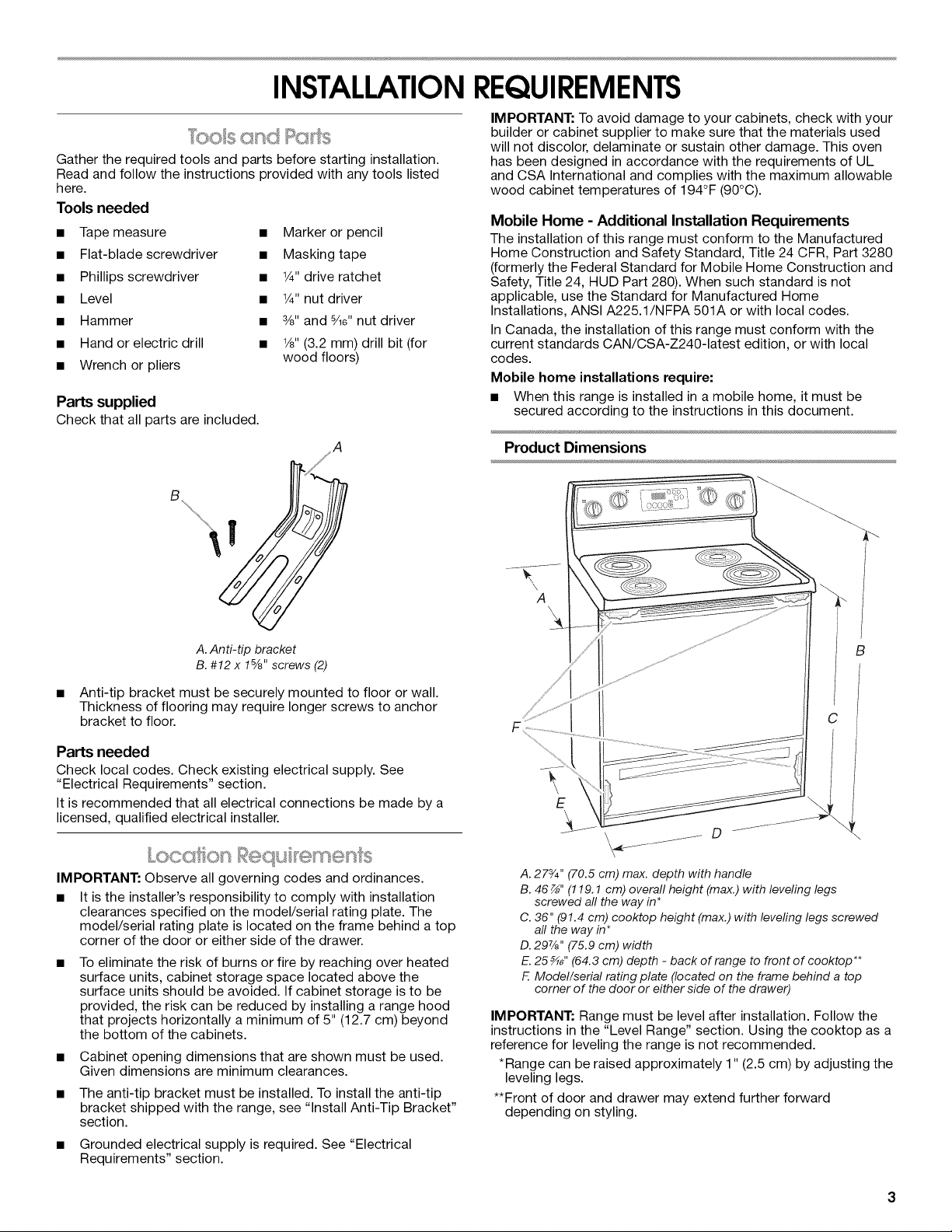
Parts supplied
Check that all parts are included.
• Marker or pencil
• Masking tape
• 1¼.drive ratchet
• 1_" nut driver
• 3/8"and 8/ld' nut driver
• 1/8"(3.2 mm) drill bit (for
wood floors)
IMPORTANT: To avoid damage to your cabinets, check with your
builder or cabinet supplier to make sure that the materials used
will not discolor, delaminate or sustain other damage. This oven
has been designed in accordance with the requirements of UL
and CSA International and complies with the maximum allowable
wood cabinet temperatures of 194°F (90°C).
Mobile Home - Additional Installation Requirements
The installation of this range must conform to the Manufactured
Home Construction and Safety Standard, Title 24 CFR, Part 3280
(formerly the Federal Standard for Mobile Home Construction and
Safety, Title 24, HUD Part 280). When such standard is not
applicable, use the Standard for Manufactured Home
Installations, ANSI A225.1/NFPA 501A or with local codes.
In Canada, the installation of this range must conform with the
current standards CAN/CSA-Z240-1atest edition, or with local
codes.
Mobile home installations require:
• When this range is installed in a mobile home, it must be
secured according to the instructions in this document.
Product Dimensions
A.Anti-tip bracket
B. #12 x 1%" screws (2)
Anti-tip bracket must be securely mounted to floor or wall.
Thickness of flooring may require longer screws to anchor
bracket to floor.
Parts needed
Check local codes. Check existing electrical supply. See
"Electrical Requirements" section.
It is recommended that all electrical connections be made by a
licensed, qualified electrical installer.
IMPORTANT: Observe all governing codes and ordinances.
• It is the installePs responsibility to comply with installation
clearances specified on the model/serial rating plate. The
model/serial rating plate is located on the frame behind a top
corner of the door or either side of the drawer.
To eliminate the risk of burns or fire by reaching over heated
surface units, cabinet storage space located above the
surface units should be avoided. If cabinet storage is to be
provided, the risk can be reduced by installing a range hood
that projects horizontally a minimum of 5" (12.7 cm) beyond
the bottom of the cabinets.
• Cabinet opening dimensions that are shown must be used.
Given dimensions are minimum clearances.
• The anti-tip bracket must be installed. To install the anti-tip
bracket shipped with the range, see "Install Anti-Tip Bracket"
section.
• Grounded electrical supply is required. See "Electrical
Requirements" section.
A
(
B
E
\
A. 273/4" (70.5 cm) max. depth with handle
B. 46 _" (119.1 cm) overall height (max.) with leveling legs
screwed all the way in*
C. 36" (91.4 cm) cooktop height (max.) with leveling legs screwed
all the way in*
D. 29%" (75.9 cm) width
E.25 _" (64.3 cm) depth - back of range to front of cooktop**
F. Model/serial rating plate (located on the frame behind a top
corner of the door or either side of the drawer)
IMPORTANT: Range must be level after installation. Follow the
instructions in the "Level Range" section. Using the cooktop as a
reference for leveling the range is not recommended.
*Range can be raised approximately 1" (2.5 cm) by adjusting the
leveling legs.
**Front of door and drawer may extend further forward
depending on styling.
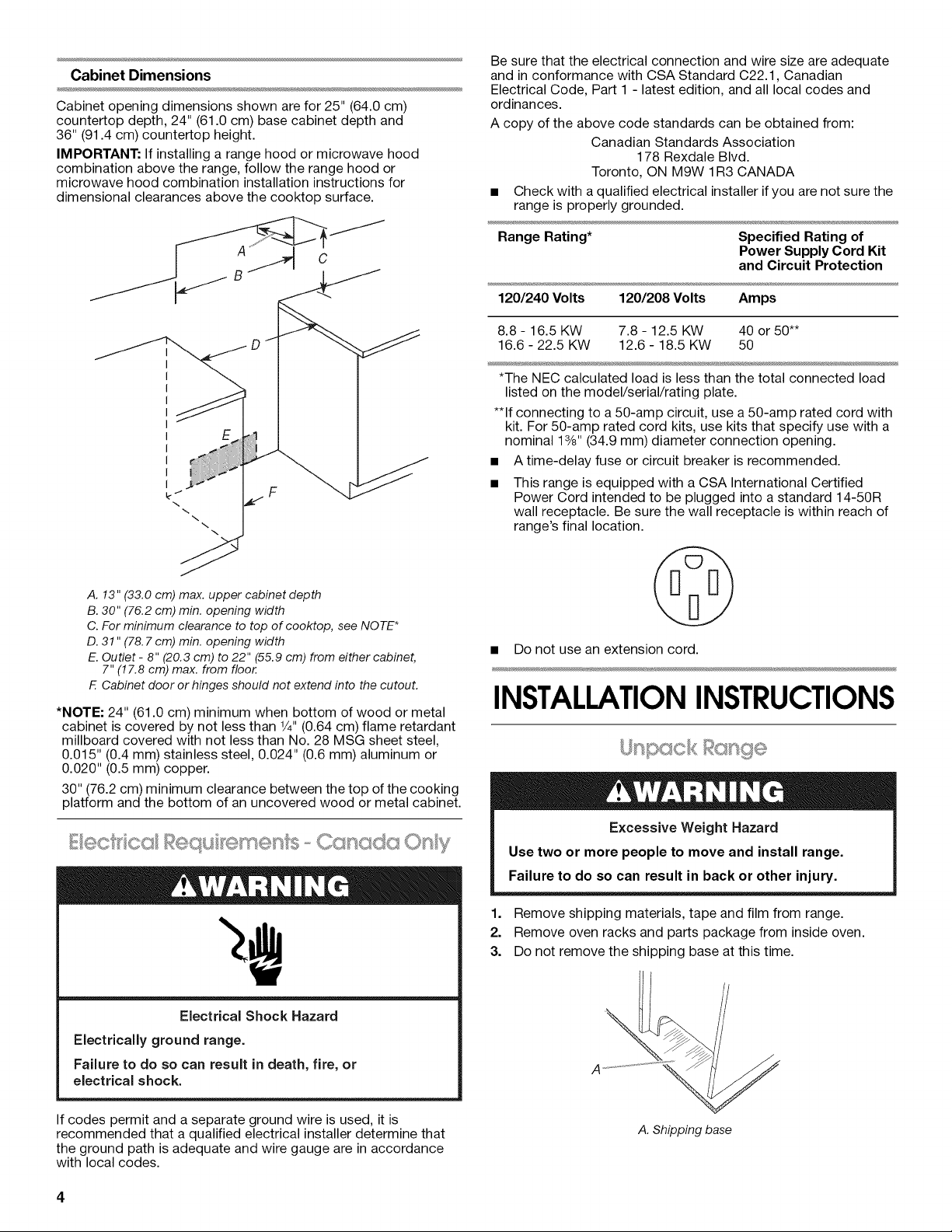
Cabinet Dimensions
Cabinet opening dimensions shown are for 25" (64.0 cm)
countertop depth, 24" (61.0 cm) base cabinet depth and
36" (91.4 cm) countertop height.
IMPORTANT: If installing a range hood or microwave hood
combination above the range, follow the range hood or
microwave hood combination installation instructions for
dimensional clearances above the cooktop surface.
Be sure that the electrical connection and wire size are adequate
and in conformance with CSA Standard C22.1, Canadian
Electrical Code, Part 1 - latest edition, and all local codes and
ordinances.
A copy of the above code standards can be obtained from:
Canadian Standards Association
178 Rexdale Blvd.
Toronto, ON M9W 1R3 CANADA
• Check with aqualified electrical installer if you are not sure the
range is properly grounded.
E
\
\
\
\
A. 13" (33.0 cm) max. upper cabinet depth
B. 30" (76.2 cm) min. opening width
C. For minimum clearance to top of cooktop, see NOTE*
D. 31" (78. 7 cm) min. opening width
E. Outlet - 8" (20.3 cm) to 22" (55.9 cm) from either cabinet,
7" (17.8 cm) max. from floor.
E Cabinet door or hinges should not extend into the cutout.
*NOTE: 24" (61.0 cm) minimum when bottom of wood or metal
cabinet is covered by not less than 1/4"(0.64 cm) flame retardant
millboard covered with not less than No. 28 MSG sheet steel,
0.015" (0.4 mm) stainless steel, 0.024" (0.6 mm) aluminum or
0.020" (0.5 mm) copper.
30" (76.2 cm) minimum clearance between the top of the cooking
platform and the bottom of an uncovered wood or metal cabinet.
Range Rating* Specified Rating of
Power Supply Cord Kit
and Circuit Protection
120/240 Volts 120/208 Volts Amps
8.8 - 16.5 KW 7.8 - 12.5 KW 40 or 50**
16.6 - 22.5 KW 12.6 - 18.5 KW 50
*The NEC calculated load is less than the total connected load
listed on the model/serial/rating plate.
**If connecting to a 50-amp circuit, use a50-amp rated cord with
kit. For 50-amp rated cord kits, use kits that specify use with a
nominal 13/8"(34.9 mm) diameter connection opening.
A time-delay fuse or circuit breaker is recommended.
This range is equipped with a CSA International Certified
Power Cord intended to be plugged into a standard 14-50R
wall receptacle. Be sure the wall receptacle is within reach of
range's final location.
• Do not use an extension cord.
INSTALLATIONINSTRUCTIONS
k n,pcxck t csr@e
Excessive Weight Hazard
Use two or more people to move and install range.
Failure to do so can result in back or other injury.
Electrical Shock Hazard
Electrically ground range.
Failure to do so can result in death, fire, or
electrical shock.
If codes permit and a separate ground wire is used, it is
recommended that a qualified electrical installer determine that
the ground path is adequate and wire gauge are in accordance
with local codes.
1,
Remove shipping materials, tape and film from range.
2.
Remove oven racks and parts package from inside oven.
3.
Do not remove the shipping base at this time.
A,Shipping base
4=
On Ranges Equipped with a Storage Drawer:
Remove the storage drawer. See the "Storage Drawer"
section. Use a 1¼,,drive ratchet to lower the rear leveling legs
one-half turn. Use a wrench or pliers to lower front leveling
legs one-half turn.
A D
...."2 .........
y///'
C
B
A. ¼" drive ratchet
B. Rear levering leg
C. Wrench or pliers
D. Front leveling leg
On Ranges Equipped with a Warming Drawer or Premium
Storage Drawer:
On ranges equipped with a warming drawer or premium
storage drawer, the rear legs cannot be accessed by removing
the warming drawer or premium storage drawer. It will be
necessary to adjust the rear legs from outside the range. Use
wrench or pliers to lower the front and rear leveling legs one-
half turn.
C
\
A
B
A. Rear levering leg
B. Wrench or pliers
C. Front leveling leg
nsks As'st p B ccsck®
Tip Over Hazard
A child or adult can tip the range and be killed.
Install anti-tip bracket to floor or wall per installation
instructions.
Slide range back so rear range foot is engaged in the
slot of the anti-tip bracket.
Re-engage anti-tip bracket if range is moved.
Do not operate range without anti-tip bracket installed
and engaged.
Failure to follow these instructions can result in death
or serious burns to children and adults.
1=
Remove the anti-tip bracket from where it is taped inside the
storage drawer or warming drawer.
2.
Determine which mounting method to use: floor or wall.
If you have a stone or masonry floor, you can use the wall
mounting method. If you are installing the range in a mobile
home, you must secure the range to the floor.
3.
Determine and mark centerline of the cutout space. The
mounting can be installed on either the left side or right side of
the cutout. Position mounting bracket against the wall in the
cutout so that the V-notch of the bracket is 12%6" (31.9 cm)
from centerline as shown.
II B
Centerlioe!
J J __
/
A. 12_" (31.9 cm)
B. Bracket V-notch
4=
Drill two 1/8"(3 mm) holes that correspond to the bracket holes
of the determined mounting method. See the following
illustrations.
Floor Mounting
Rear position Front position Diagonal (2 options)
 Loading...