

Whirlpool YWEC310S0FS, YWEE510S0FB, YWEE510S0FS, YWEC310S0FW, YWEE510S0FW Installation Instructions
...
IMPORTANT:
Sa
IMPOR
À conser
.
INSTALLATION INSTRUCTIONS
FRONT CONTROL ELECTRIC RANGES
INSTRUCTIONS D’INSTALLATION DES CUISINIÈRES
ÉLECTRIQUES À COMMANDES FRONTALES
Table of Contents/Table des matières
RANGE SAFETY .............................................................................2
INSTALLATION REQUIREMENTS .................................................3
Tools and Parts .............................................................................3
Location Requirements ................................................................3
Electrical Requirements - Canada Only .......................................5
INSTALLATION INSTRUCTIONS ...................................................6
Unpack Range..............................................................................6
Install Anti-Tip Bracket .................................................................6
Adjust Leveling Legs ....................................................................7
Level Range ..................................................................................7
Verify Anti-Tip Bracket Is Installed and Engaged ........................8
Remove/Replace Drawer .............................................................8
Oven Door ....................................................................................8
Complete Installation ...................................................................9
SÉCURITÉ DE LA CUISINIÈRE ...................................................10
EXIGENCES D’INSTALLATION ...................................................11
Outillage et pièces ......................................................................11
Exigences d’emplacement .........................................................12
Spécifications électriques – ......................................................13
INSTRUCTIONS D’INSTALLATION .............................................14
Déballage de la cuisinière ..........................................................14
Installation de la bride antibasculement ....................................14
Réglage des pieds de nivellement .............................................15
Réglage de l’aplomb de la cuisinière .........................................16
Vérifier que la bride antibasculement est bien installée
et engagée ..................................................................................16
Dépose et réinstallation du tiroir ................................................16
Porte du four ..............................................................................16
Achever l’installation ..................................................................17
ve for local electrical inspector's use.
W10842014A
TANT :
ver pour consultation par l'inspecteur local des installations électriques
RANGE SAFETY
Your safety and the safety of others are very important.
We have provided many important safety messages in this manual and on your appliance. Always read and obey all safety
messages.
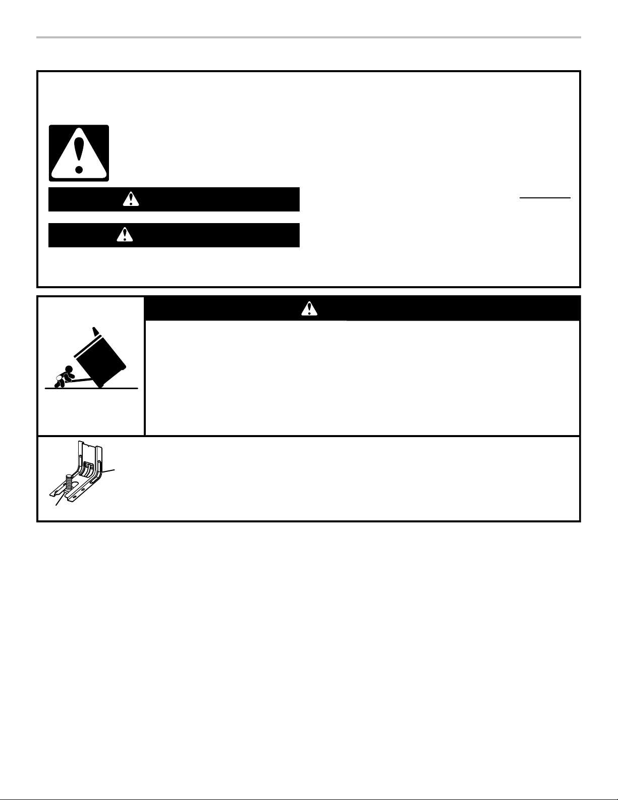
This is the safety alert symbol.
This symbol alerts you to potential hazards that can kill or hurt you and others.
All safety messages will follow the safety alert symbol and either the word “DANGER” or “WARNING.”
These words mean:
You can be killed or seriously injured if you don't immediately
DANGER
WARNING
All safety messages will tell you what the potential hazard is, tell you how to reduce the chance of injury, and tell you what can
happen if the instructions are not followed.
A child or adult can tip the range and be killed.
Install anti-tip bracket to floor or wall per installation instructions.
Slide range back so rear range foot is engaged in the slot of the anti-tip bracket.
Re-engage anti-tip bracket if range is moved.
Do not operate range without anti-tip bracket installed and engaged.
Failure to follow these instructions can result in death or serious burns to children and adults.
follow instructions.
You
can be killed or seriously injured if you don't
instructions.
WARNING
Tip Over Hazard
follow
Range Foot
Anti-Tip
Bracket
To verify the anti-tip bracket is installed and engaged:
• Slide range forward.
• Look for the anti-tip bracket securely attached to floor or wall.
• Slide range back so rear range foot is under anti-tip bracket.
• See installation instructions for details.
2

INSTALLATION REQUIREMENTS
Tools and Parts
Gather the required tools and parts before starting installation.
Read and follow the instructions provided with any tools
listed here.
Tools Needed
■ Tape measure
■ Phillips screwdriver
■ Level
■ Hand or electric drill
■ Wrench or pliers
■ Marker or pencil
8
■ ¹⁄
" (3.2 mm) drill bit (for wood floors)
■ Flashlight
Parts Supplied
Check that all parts are included.
■ #10 x 1
■ Anti-tip bracket (inside oven cavity)
5
⁄8” (4.1 cm) screws (for mounting anti-tip bracket) (2)
Anti-tip bracket must be securely mounted to the back wall
or floor. Thickness of flooring may require longer screws to
anchor bracket to subfloor. Longer screws are available from
your local hardware store.
Location Requirements
IMPORTANT: Observe all governing codes and ordinances.
■ It is the installer’s responsibility to comply with installation
clearances specified on the model/serial/rating plate. The
model/serial/rating plate is located behind the oven door
on the top right-hand side of the oven frame.
■ The range should be located for convenient use in the
kitchen.
■ Recessed installations must provide complete enclosure of
the sides and rear of the range.
■ To eliminate the risk of burns or fire by reaching over the
heated surface units, cabinet storage space located above
the surface units should be avoided. If cabinet storage
is to be provided, the risk can be reduced by installing a
range hood or microwave hood combination that projects
horizontally a minimum of 5" (12.7 cm) beyond the bottom of
the cabinets.
■ All openings in the wall or floor where range is to be installed
must be sealed.
■ Cabinet opening dimensions that are shown must be used.
Given dimensions are minimum clearances.
■ The anti-tip bracket must be installed. To install the anti-tip
bracket shipped with the range, see “Install Anti-Tip Bracket”
section.
■ Grounded electrical supply is required. See the appropriate
“Electrical Requirements” section.
■ Contact a qualified floor covering installer to check that the
floor covering can withstand at least 200°F (93°C).
■ Use an insulated pad or ¼" (0.64 cm) plywood under range
if installing range over carpeting.
IMPORTANT: To avoid damage to your cabinets, check with
your builder or cabinet supplier to make sure that the materials
used will not discolor, delaminate, or sustain other damage. This
oven has been designed in accordance with the requirements
of UL and CSA International and complies with the maximum
allowable wood cabinet temperatures of 194°F (90°C).
3
Mobile Home - Additional Installation Requirements
The installation of this range must conform to the Manufactured
Home Construction and Safety Standard, Title 24 CFR,
Part 3280 (formerly the Federal Standard for Mobile Home
Construction and Safety, Title 24, HUD Part 280). When such
standard is not applicable, use the Standard for Manufactured
Home Installations, ANSI A225.1/NFPA 501A or with local codes.
In Canada, the installation of this range must conform with the
current standards CAN/CSA-A240-latest edition, or with local
codes.
Mobile Home Installations Require:
■ When this range is installed in a mobile home, it must be
secured to the floor during transit. Any method of securing
the range is adequate as long as it conforms to the
standards listed above.
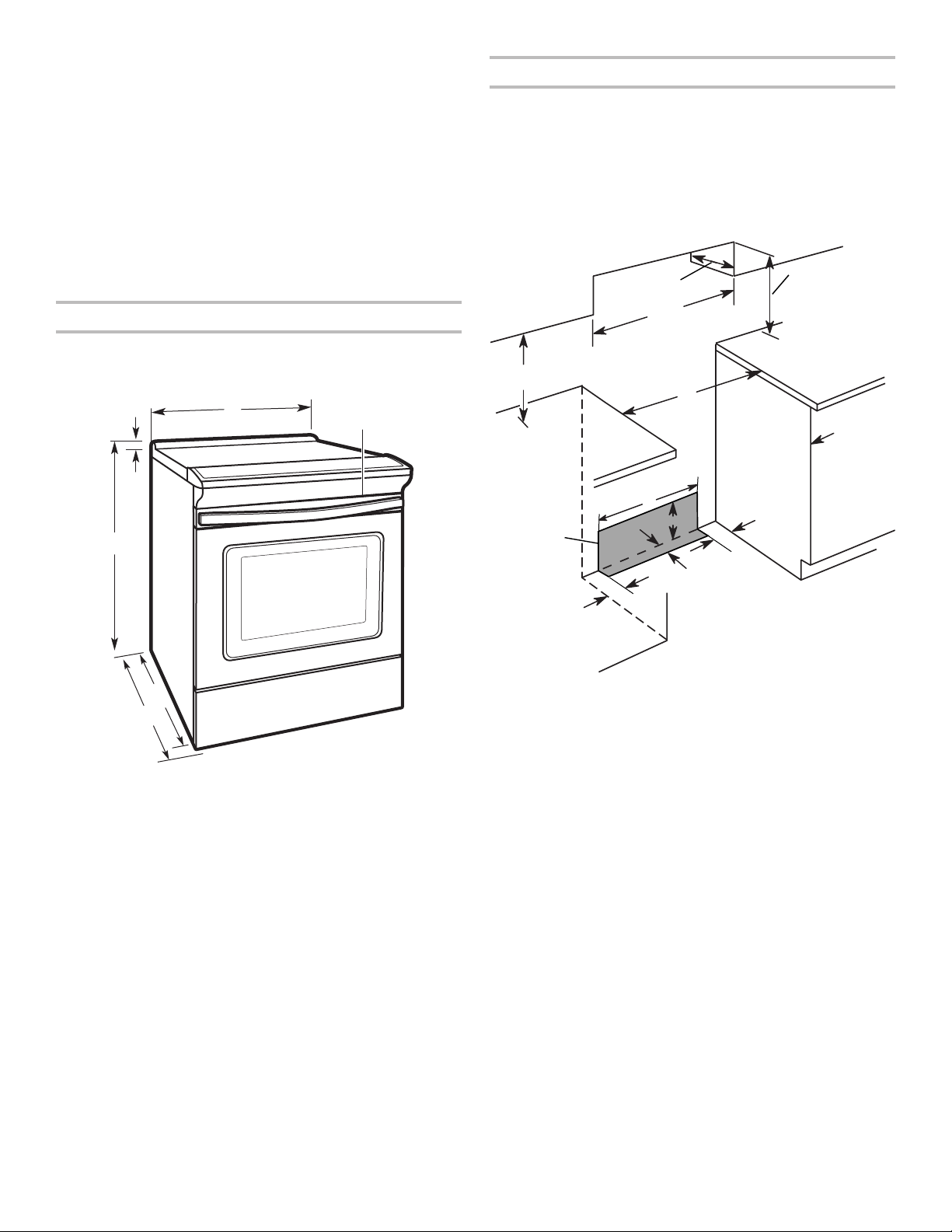
Product Dimensions
This manual covers several models. Your model may appear
different from the models depicted. Dimensions given are
maximum dimensions across all models.
A
B
C
D
Cabinet Dimensions
Cabinet opening dimensions shown are for 25" (64.0 cm)
countertop depth, 24" (61.0 cm) base cabinet depth, and 36"
(91.4 cm) countertop height.
IMPORTANT: If installing a range hood or microwave hood
combination above the range, follow the range hood or
microwave hood combination installation instructions for
dimensional clearances above the cooktop surface.
Range may be installed next to combustible walls with zero
clearance.
B
C
A
E
G
H
F
J
D
K
I
E
F
A. 1³⁄16" (3.0 cm) height from cooktop
to top of vent
B. 297⁄8" (75.9 cm)
C. Model/serial/rating plate (located
behind the oven door on the top
right-hand side of the oven frame)
D. 36" (91.4 cm) height to top of
cooktop edge with leveling legs
screwed all the way in*
IMPORTANT: Range must be level after installation. Follow the
instructions in the “Level Range” section. Using the cooktop as
a reference for leveling the range is not recommended.
* Range can be raised approximately 1" (2.5 cm) by adjusting
the leveling legs.
E. 2825⁄64" (72.1 cm) max. depth
from front of console to
back of range
F. 291⁄64" (73.7 cm) max. depth
from handle to back of
range
I
A. 18" (45.7 cm) upper side cabinet to countertop
B. 13" (33 cm) max. upper cabinet depth
C. 30" (76.2 cm) min. opening width
D. For minimum clearance to top of cooktop, see NOTE*.
E. 30" (76.2 cm) min. opening width
F. The shaded area is recommended for installation of grounded
outlet.
G. 13¹⁄8" (33.3 cm)
H. 7¹¹⁄16" (19.5 cm)
I. 4¹³⁄16" (12.2 cm)
J. 3¹¹⁄16" (9.4 cm)
K. Cabinet door or hinges should not extend into the cutout.
* NOTE: 24" (61.0 cm) minimum when bottom of wood or
metal cabinet is shielded by not less than ¹⁄4" (0.64 cm) flame
retardant millboard covered with not less than No. 28 MSG
sheet steel, 0.015" (0.4 mm) stainless steel, 0.024" (0.6 mm)
aluminum or 0.020" (0.5 mm) copper.
30" (76.2 cm) minimum clearance between the top of the
cooking platform and the bottom of an uncovered wood or
metal cabinet.
4
Electrical Requirements - Canada Only
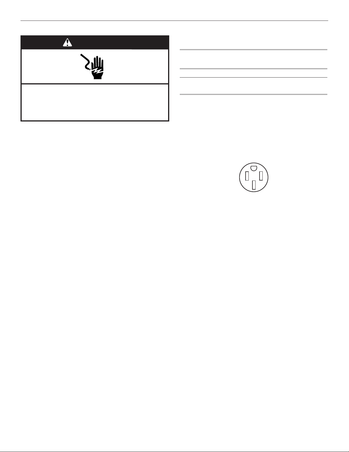
WARNING
Electrical Shock Hazard
Electrically ground range.
Failure to do so can result in death, fire, or
electrical shock.
If codes permit and a separate ground wire is used, it is
recommended that a qualified electrical installer determine that
the ground path is adequate and wire gauge are in accordance
with local codes.
Be sure that the electrical connection and wire size are adequate
and in conformance with CSA Standard C22.1, Canadian
Electrical Code, Part 1 - latest edition, and all local codes and
ordinances.
A copy of the above code standards can be obtained from:
Canadian Standards Association
178 Rexdale Blvd.
Toronto, ON M9W 1R3 CANADA
■ Check with a qualified electrical installer if you are not sure
the range is properly grounded.
Range Rating* Specified Rating of
Power Supply Cord Kit
and Circuit Protection
120/240 Volts 120/208 Volts Amps
8.8 - 16.5 KW 7.8 - 12.5 KW 40 or 50**
16.6 - 22.5 KW 12.6 - 18.5 KW 50
* The NEC calculated load is less than the total connected load
listed on the model/serial/rating plate.
**If connecting to a 50-amp circuit, use a 50-amp rated cord with
kit. For 50-amp rated cord kits, use kits that specify use with a
nominal 1³⁄8" (3.5 cm) diameter connection opening.
■ A circuit breaker is recommended.
■ This range is equipped with a CSA International Certified
Power Cord intended to be plugged into a standard 14-50R
wall receptacle. Be sure the wall receptacle is within reach of
range’s final location.
■ Do not use an extension cord.
■ The tech sheet and wiring diagram are located on the back
of the range in a plastic bag.
5
INSTALLATION INSTRUCTIONS
WARNING
Unpack Range
WARNING
Excessive Weight Hazard
Use two or more people to move and install range.
Failure to do so can result in back or other injury.
1. Remove shipping materials, tape, and film from the range.
Keep cardboard bottom under range. Do not dispose of
anything until the installation is complete.
2. Remove oven racks and parts package from oven and
shipping materials.
3. To remove cardboard bottom, first take 4 cardboard corners
from the carton. Stack 1 cardboard corner on top of another.
Repeat with the other 2 corners. Place them lengthwise on
the floor behind the range to support the range when it is laid
on its back.
4. Using 2 or more people, firmly grasp the range and gently lay
it on its back on the cardboard corners.
5. Remove cardboard bottom.
The leveling legs can be adjusted while the range is on its back.
See the “Adjust Leveling Legs” section.
NOTE: To place range back up into a standing position, put a
sheet of cardboard or hardboard on the floor in front of range to
protect the flooring. Using 2 or more people, stand range back
up onto the cardboard or hardboard.
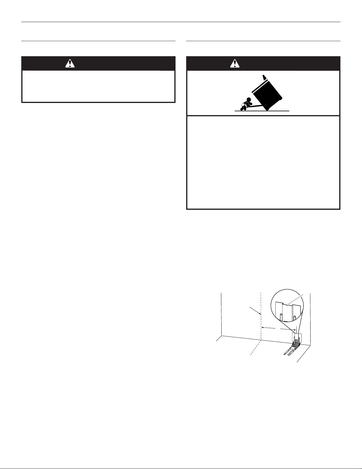
Install Anti-Tip Bracket
Tip Over Hazard
A child or adult can tip the range and be killed.
Install anti-tip bracket to floor or wall per installation
instructions.
Slide range back so rear range foot is engaged in the
slot of the anti-tip bracket.
Re-engage anti-tip bracket if range is moved.
Do not operate range without anti-tip bracket installed
and engaged.
Failure to follow these instructions can result in death
or serious burns to children and adults.
1. Remove the anti-tip bracket from the inside of the oven.
2. Determine which mounting method to use: floor or wall.
If you have a stone or masonry floor, you can use the wall
mounting method. If you are installing the range in a mobile
home, you must secure the range to the floor.
This anti-tip bracket and screws can be used with wood or
metal studs.
3. Determine and mark centerline of the cutout space. The
mounting bracket can be installed on either the left-hand
or right-hand side of the cutout. Position mounting bracket
against the wall in the cutout so that the V-notch of the
bracket is 12½" (31.8 cm) from centerline as shown.
B
Centerline
A. 12½" (31.8 cm)
B. Bracket V-notch
6
A
 Loading...