

Whirlpool YUMV4084B Dimension Guide
PRODUCT MODEL NUMBERS
VENTING REQUIREMENTS
Electrical Requirements
Required:
●
A 120 volt, 60 Hz, AC only, 15- or 20-amp electrical supply with a fuse or circuit
breaker.
Recommended:
●
A time-delay fuse or time-delay circuit breaker.
●
A separate circuit serving only this microwave oven.
Microwave Hood Combination
Because Whirlpool Corporation policy includes a continuous commitment to improve
our products, we reserve the right to change materials and specifications without notice.
Dimensions are for planning purposes only. For complete details, see Installation
Instructions packed with product. Specifications subject to change without notice.
Ref. W10589884A
9/13
This section is intended for architectural designer and builder/contractor
reference only.
NOTES:
●
If installing for recirculation, venting must be routed up and out through an
exhaust register (not provided) in a kitchen soffit. A charcoal filter kit (not
provided) should be used. See “Assistance” section for information on ordering.
●
Vent materials needed for installation are not provided with microwave hood
combination.
●
We do not recommend using a flexible metal vent.
●
To avoid possible product damage, be sure to vent air outside, unless using
recirculation installation. Do not vent exhaust air into concealed spaces, such as
spaces within walls or ceilings, attics, crawl spaces or garages.
For optimal venting installation, we recommend:
●
using roof or wall caps that have back draft dampers
●
using a rigid metal vent
●
using the most direct route by minimizing the length of the vent and number of
elbows to provide efficient performance
●
using uniformly sized vents
●
using duct tape to seal all joints in the vent system
●
using caulking compound to seal exterior wall or roof opening around cap
●
for optimal hood performance, do not install 2 elbows together
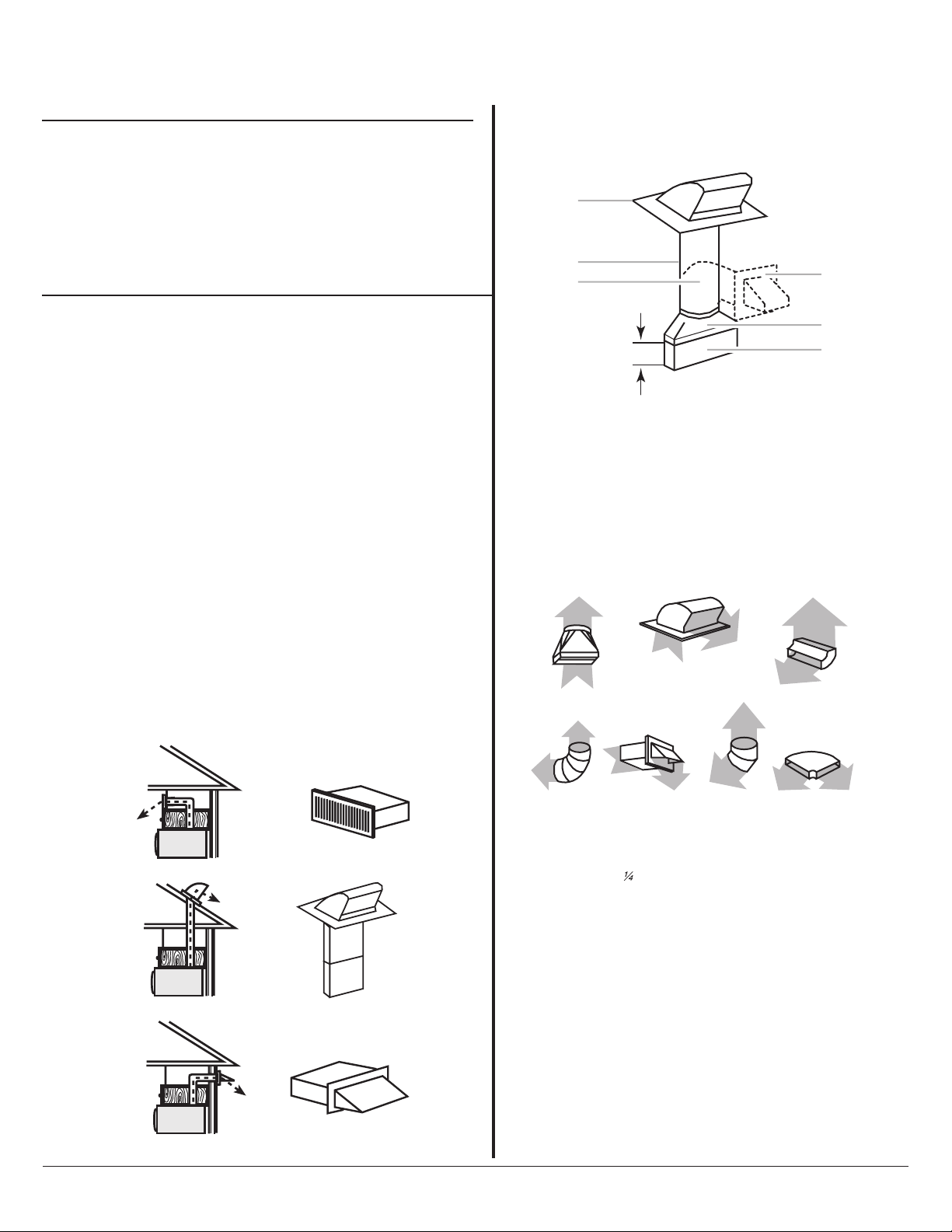
If rectangular to round transition is used, be sure there is at least 3" (7.6 cm) of
clearance between the top of the damper assembly and the transition piece. See
“Rectangular to Round Transition” illustration.
YUMV4084B
r
g
Rectangular to Round Transition
NOTE: The minimum 3" (7.6 cm) clearance must exist between the top of
the damper assembly and the rectangular to round transition piece so that
the damper can open freely and fully.
Recommended Standard Fittings
The following length equivalents are for use when figuring vent length. See
the examples in “Recommended Vent Length.”
Page 1 of 4
A
B
C
D
E
3" (7.6 cm)
A. Roof cap
B. 6" (15.2 cm) min. diameter round vent
C. Elbow (for wall venting only)
D. Wall cap
E. 3
¹⁄₄
" x 10" to 6" (8.3 x 25.4 cm to 15.2 cm)
rectangular to round transition piece
F. Vent extension piece, at least 3" (7.6 cm) high
F
A B C
Recirculation venting Exhaust registe
Roof venting Roof cap
Wall ventin
Wall cap
D E F G
¹⁄₄
A. Rectangular to round transition piece: 3
(8.3 x 25.4 cm to 15.2 cm = 1.5 m)
B. Roof cap: 3
C. 90° elbow: 3
D. 90° elbow: 6" = 10 ft (15.2 cm = 3 m)
E. Wall cap: 3
F. 45° elbow: 6" = 5 ft (15.2 cm = 1.5 m)
G. 90° flat elbow: 3
¹⁄₄
" x 10" = 24 ft (8.3 x 25.4 cm = 7.3 m)
" x 10" = 25 ft (8.3 x 25.4 cm = 7.6 m)
¹⁄₄
" x 10" = 40 ft (8.3 x 25.4 cm = 12.2 m)
¹⁄₄
" x 10" = 10 ft (8.3 x 25.4 cm = 3 m)
" x 10" to 6" = 5 ft
Recommended Vent Length
A 3¹⁄₄" x 10" (8.3 x 25.4 cm) rectangular or 6" (15.2 cm) round vent should
be used.
The total length of the vent system including straight vent, elbow(s),
transitions and wall or roof caps must not exceed the equivalent of 140 ft
(42.7 m) for either type of vent. See “Recommended Standard Fittings”
section for equivalent lengths.
For best performance, use no more than three 90° elbows.
To calculate the length of the system you need, add the equivalent lengths of
each vent piece used in the system. See the following examples:
If the existing vent is round, a rectangular to round transition piece must be
used. In addition, a rectangular 3" (7.6 cm) extension vent between the
damper assembly and rectangular to round transition piece must be installed
to keep the damper from sticking.
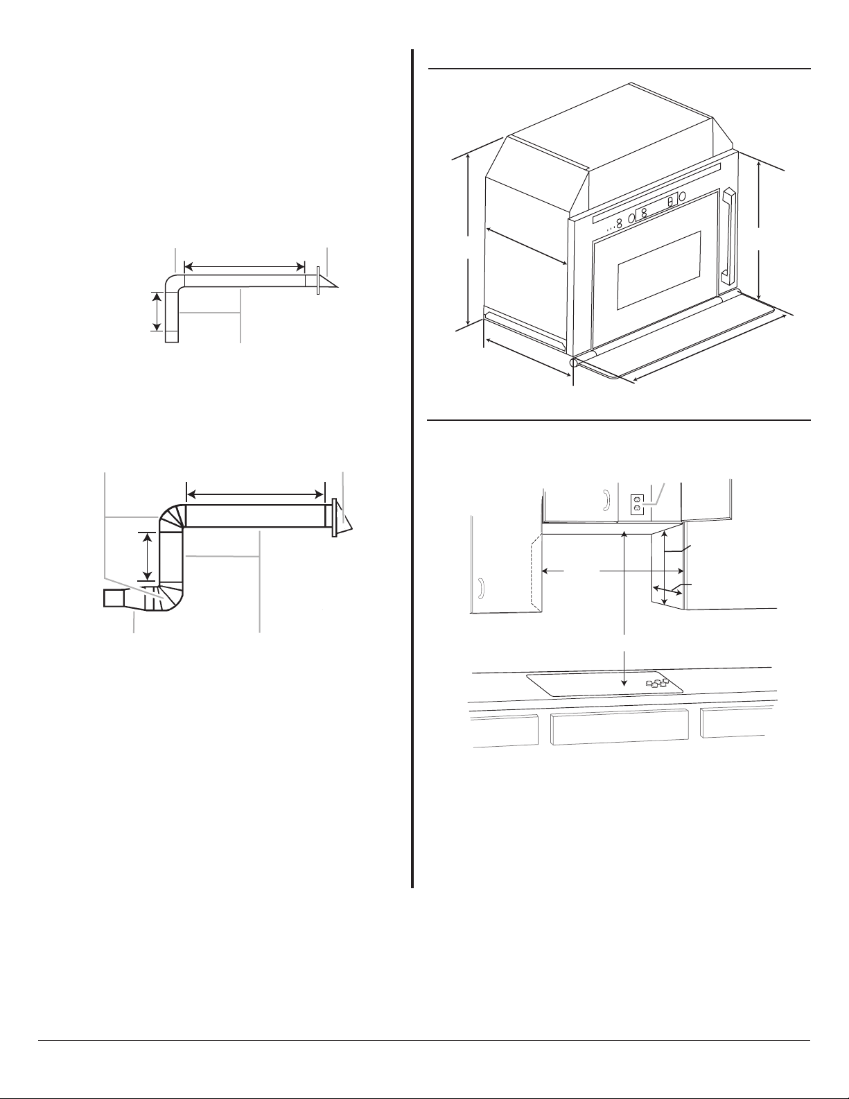
PRODUCT DIMENSIONS
CABINET OPENING DIMENSIONS
NOTE: The grounded 3 prong outlet must be inside the upper cabinet. See
“Electrical Requirements” section.
*Measure from the front edges of the side cabinets.
**For installation with stainless steel filler panel.
NOTE: To avoid stress on the power cord, a minimum of 1¹⁄₂" (3.8 cm) must exist
between the top surface of the microwave oven’s upper component housing and
the bottom of the upper cabinet.
Because Whirlpool Corporation policy includes a continuous commitment to improve
our products, we reserve the right to change materials and specifications without notice.
Dimensions are for planning purposes only. For complete details, see Installation
Instructions packed with product. Specifications subject to change without notice.
Ref. W10589884A
9/13
Page 2 of 4
3¹⁄₄" x 10" (8.3 x 25.4 cm) vent system = 73 ft (22.2 m) total
A B
6 ft (1.8 m)
2 ft
(0.6 m)
C
A. One 3
B. 1 wall cap = 40 ft (12.2 m)
C. 2 ft (0.6 m) + 6 ft (1.8 m) straight = 8 ft (2.4 m)
¹⁄₄
" x 10" (8.3 x 25.4 cm) 90° elbow = 25 ft (7.6 m)
6" (15.2 cm) vent system = 73 ft (22.2 m) total
A B
6 ft (1.8 m)
11
20⁷⁄₁₆"
(51.9 cm)
¹³⁄₁₆"
12⁵⁄₈"
(30.0 cm)
(32.0 cm)
⁹⁄₁₆" (59.8 cm)
23
16¹⁄₈"
(40.9 cm)
A
2 ft
(0.6 m)
C D
A. Two 90° elbows = 20 ft (6.1 m)
B. 1 wall cap = 40 ft (12.2 m)
C. 1 rectangular to round transition piece = 5 ft (1.5 m)
D. 2 ft (0.6 m) + 6 ft (1.8 m) straight = 8 ft (2.4 m)
21" (53.3 cm) min.
23
⁷⁄₈"
(60.6 cm) min.*
24
¹⁄₈"
(61.2 cm) max.*
39" (99.1 cm) min.
A. Grounded 3 prong outlet
21⁵⁄₈" (54.9 cm)**
11¹⁵⁄₁₆" (30.3 cm) min.
13³⁄₄" (34.9 cm) max.
 Loading...