

Whirlpool xcgm2765fq, xcem2765fq Installation Instructions

INSTALLATION INSTRUCTIONS
Original instructiOns
cOmmercial gas Or
mODels Xcem2765 anD Xcgm2765
electric
Dryer
INSTRUCTIONS D’INSTALLATION
instructiOns D’Origine
sèche-linge À gaz Ou
mODèles Xcem2765 et Xcgm2765
électrique
À usage cOmmercial
INSTRUCCIONES DE INSTALACIÓN
instrucciOnes Originales
secaDOra a gas O
mODelOs Xcem2765 y Xcgm2765
eléctrica
cOmercial
ISTRUZIONI D’INSTALLAZIONE
istruziOni Originali
asciugatrice a gas O
mODelli Xcem2765 e Xcgm2765
elettrica
cOmmerciale
www.whirlpoolcommerciallaundry.com
W10868678A

TABLE OF CONTENTS
TABLE DES MATIÈRES
DRYER SAFETY ........................................................................3
FOR OWNER
MAINTENANCE INSTRUCTIONS............................................ 6
IF YOU NEED ASSISTANCE ................................................... 6
FOR WHIRLPOOL AUTHORIZED SERVICE PERSON
TOOLS & PARTS ..................................................................... 7
DIMENSIONS/CLEARANCES ............................................... 8
DRYER INSTALLATION REQUIREMENTS ........................... 9
INSTALLING LEVELING LEGS .............................................. 10
LEVELING ............................................................................... 11
ELECTRIC DRYER INSTALLATION REQUIREMENTS ...... 12
GAS DRYER INSTALLATION REQUIREMENTS ................. 13
DRYER VENTING REQUIREMENTS ................................... 15
GAS SUPPLY CONNECTION ............................................... 17
TECHNICAL SPECIFICATIONS–GAS DRYER ..................... 18
COMPLETE INSTALLATION ................................................. 19
REVERSING DRYER DOOR SWING .................................... 20
DRYER DISPOSAL ................................................................. 21
WARRANTY ........................................................................... 22
SÉCURITÉ DU SECHE-LINGE ............................................... 23
POUR LE PROPRIÉTAIRE
INSTRUCTIONS D’ENTRETIEN ............................................ 26
SI VOUS AVEZ BESOIN D'ASSISTANCE .............................. 26
POUR LE PERSONNEL D’ENTRETIEN
AUTORISÉ PAR WHIRLPOOL
OUTILS ET PIÈCES ................................................................ 27
DIMENSIONS/DISTANCES DE DÉGAGEMENT ................... 28
EXIGENCES D’INSTALLATION POUR
LE SECHE-LINGE .................................................................. 29
INSTALLATION DES PIEDS DE NIVELLEMENT .................. 30
NIVELLEMENT ....................................................................... 31
EXIGENCES D’INSTALLATION POUR
LE SECHE-LINGE ÉLECTRIQUE .......................................... 32
EXIGENCES D’INSTALLATION POUR
LE SECHE-LINGE À GAZ ...................................................... 33
EXIGENCES CONCERNANT L’ÉVACUATION
DU SECHE-LINGE ................................................................. 35
RACCORDEMENT A LA CANALISATION DE GAZ .............. 37
CARACTÉRISTIQUES TECHNIQUES —
SECHE-LINGE À GAZ ............................................................ 38
ACHEVER L’INSTALLATION .................................................. 39
INVERSION DU SENS D’OUVERTURE DE LA PORTE ........ 40
ELIMINATION DU SECHE-LINGE ......................................... 41
GARANTIE ............................................................................. 42
ÍNDICE
SEGURIDAD DE LA SECADORA ........................................... 43
PARA EL PROPIETARIO
INSTRUCCIONES DE MANTENIMIENTO............................. 46
SI NECESITA ASISTENCIA .................................................... 46
PARA EL PERSONAL DE SERVICIO
AUTORIZADO DE WHIRLPOOL
HERRAMIENTAS Y PIEZAS................................................... 47
DIMENSIONES Y ESPACIOS LIBRES................................... 48
REQUISITOS DE INSTALACIÓN DE LA SECADORA .......... 49
INSTALACIÓN DE LAS PATAS NIVELADORAS.................... 50
NIVELACIÓN .......................................................................... 51
REQUISITOS DE INSTALACIÓN DE LA
SECADORA ELÉCTRICA ....................................................... 52
REQUISITOS DE INSTALACIÓN DE LA
SECADORA A GAS ................................................................ 53
REQUISITOS DE VENTILACIÓN DE LA SECADORA .......... 55
CONEXIÓN DEL SUMINISTRO DE GAS............................... 58
ESPECIFICACIONES TÉCNICAS - SECADORA A GAS ...... 59
INSTALACIÓN COMPLETA ................................................... 60
CAMBIO DE SENTIDO DE LA ABERTURA
DE LA PUERTA ....................................................................... 61
ELIMINACIÓN DE LA SECADORA ....................................... 62
GARANTÍA .............................................................................. 63
INDICE
SICUREZZA DELL'ASCIUGATRICE....................................... 64
PER IL PROPRIETARIO
ISTRUZIONI PER LA MANUTENZIONE ............................... 67
COME RICHIEDERE ASSISTENZA ...................................... 67
PER IL PERSONALE DI ASSISTENZA
AUTORIZZATO WHIRLPOOL
ATTREZZI E COMPONENTI .................................................. 68
DIMENSIONI/SPAZI ............................................................. 69
REQUISITI DELL'INSTALLAZIONE
DELL'ASCIUGATRICE ........................................................... 70
INSTALLAZIONE DEI PIEDINI DI REGOLAZIONE ............... 71
LIVELLAMENTO ..................................................................... 72
REQUISITI DELL'INSTALLAZIONE
DELL'ASCIUGATRICE ELETTRICA ...................................... 73
REQUISITI DELL'INSTALLAZIONE
DELL'ASCIUGATRICE A GAS ............................................... 74
REQUISITI DI SCARICO DELL'ASCIUGATRICE .................. 76
COLLEGAMENTO DI ALIMENTAZIONE DEL GAS .............. 78
CARATTERISTICHE TECNICHE -
ASCIUGATRICE A GAS ......................................................... 79
COMPLETAMENTO DELL'INSTALLAZIONE ....................... 80
INVERSIONE IL SENSO DI APERTURA
DELLO SPORTELLO ............................................................. 81
ELIMINAZIONE DELL'ASCIUGATRICE ................................ 82
GARANZIA ............................................................................. 83
2
DRYER SAFETY
Your safety and the safety of others are very important.
We have provided many important safety messages in this manual and on your appliance. Always read and obey all safety
messages.
This is the safety alert symbol.
This symbol alerts you to potential hazards that can kill or hurt you and others.
All safety messages will follow the safety alert symbol and either the word “DANGER” or “WARNING.”
These words mean:
You can be killed or seriously injured if you don't immediately
DANGER
WARNING
All safety messages will tell you what the potential hazard is, tell you how to reduce the chance of injury, and tell you what can
happen if the instructions are not followed.
follow instructions.
You
can be killed or seriously injured if you don't
instructions.
follow
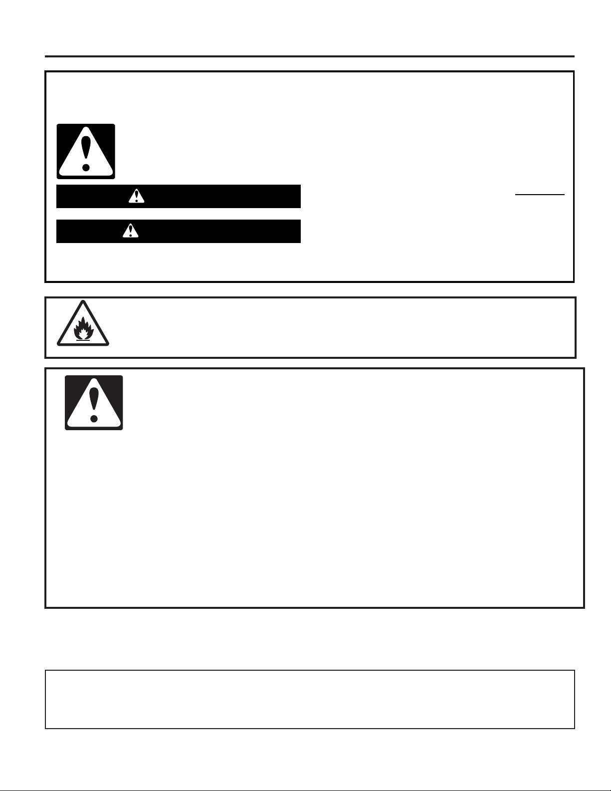
WARNING – “Risk of Fire”
This is an additional safety alert symbol that alerts you to the risk of fire.
WARNING
-
“Risk of Fire”
- Clothes dryer installation and service must be performed by a Whirlpool authorized
installer.
- Install the clothes dryer according to the manufacturer’s instructions and local codes.
- Do not install a clothes dryer with exible plastic venting materials or exible metal
(foil type) duct. If exible metal duct is installed, it must be of a specic type identied
by the appliance manufacturer as suitable for use with clothes dryers. Flexible venting
materials are known to collapse, be easily crushed, and trap lint. These conditions will
obstruct clothes dryer airow and increase the risk of re.
- To reduce the risk of severe injury or death, follow all installation instructions.
- Save these instructions.
■ It is recommended that the owner post, in a prominent location, instructions for the customer’s use in the event the customer
smells gas. This information should be obtained from your gas supplier.
■ Post the following warning in a prominent location.
FOR YOUR SAFETY
1. DO NOT USE OR STORE GAS OR OTHER FLAMMABLE MATERIALS IN THIS APPLIANCE OR NEAR THIS APPLIANCE.
2. DO NOT SPRAY AEROSOLS IN THE VICINITY OF THIS APPLIANCE WHILE IT IS IN OPERATION.
3. DO NOT MODIFY THIS APPLIANCE.
3
DRYER SAFETY
WARNING: For your safety, the information in this manual must be followed to minimize
the risk of fire or explosion, or to prevent property damage, personal injury, or death.
– Do not store or use gasoline or other flammable vapors and liquids in the vicinity of this
or any other appliance.
– WHAT TO DO IF YOU SMELL GAS:
Do not try to light any appliance.
•
Do not touch any electrical switch; do not use any phone in your building.
•
Clear the room, building, or area of all occupants.
•
Immediately call your gas supplier from a neighbor's phone. Follow the gas supplier's
•
instructions.
If you cannot reach your gas supplier, call the fire department.
•
– Installation and service must be performed by a Whirlpool authorized installer,
Whirlpool authorized service agency, or the gas supplier.
IMPORTANT: When discarding or storing your old clothes dryer, remove the door.
4

DRYER SAFETY
IMPORTANT SAFETY INSTRUCTIONS
WARNING: To reduce the risk of re, electric shock, or injury to persons when using the dryer, follow basic precautions,
including the following:
■ Read all instructions before using the dryer.
■ This dryer is intended only for drying clothes and textiles
that have been washed in water. Do not use for any other
purpose.
■ WARNING: If you smell gas, do not use the dryer or any
electrical equipment nearby. Warn other people to clear
the area. Contact the dryer owner immediately.
■ Do not place items exposed to cooking oils in your dryer.
Items contaminated with cooking oils may contribute to a
chemical reaction that could cause a load to catch re.
■ If it is unavoidable that fabrics that contain vegetable or
cooking oil or that have been contaminated by hair care
products be placed in a tumble dryer, they should rst
be washed in hot water with extra detergent – this will
reduce, but not eliminate the hazard.
■ Do not dry articles that have been previously cleaned
in, washed in, soaked in, or spotted with gas,
dry-cleaning solvents, other ammable, or explosive
substances as they give off vapors that could ignite
or explode.
■ Items that have been soiled with substances such as
acetone, alcohol, gas, kerosene, spot removers,
turpentine, waxes, and wax removers should be washed
in hot water with extra detergent before being dried in
the dryer.
■ Do not dry unwashed items in the dryer.
■ Do not use this dryer if industrial chemicals have been
used for cleaning. The possible presence of residual
quantities of aggressive or decomposed chemicals in the
load may produce damage to the dryer and harmful fumes.
■ Do not allow children to play on, in, or with the dryer.
Close supervision of children is necessary when the dryer
is used near children.
■ This dryer is not intended for use by persons (including
children) with reduced physical, sensory, or mental
capabilities, or lack of experience or knowledge,
unless they have been given supervision or instruction
concerning use of the dryer by a person responsible for
their safety.
■ Before the dryer is removed from service or discarded,
remove the door to the dryer compartment.
■ Do not reach into the dryer if the drum is moving.
■ Do not open door while dryer is in operation. It will stop.
■ When loading or re-loading the dryer, avoid touching hot
metal parts of the drum (burn risk).
■ Remove all objects from pockets such as lighters and
matches.
■ Cleaning and user maintenance shall not be made by
children without supervision.
■ WARNING: The appliance must not be supplied through
an external switching device, such as a timer, or connected
to a circuit that is regularly switched on and off by a utility.
■ The dryer must not be installed behind a lockable door, a
sliding door, or a door with a hinge on the opposite side to
that of the dryer in such a way that full opening of the dryer
door is restricted.
SAVE THESE INSTRUCTIONS
■ The appliance is intended, but not limited, to be used in
public areas.
■ Children of less than 3 years should be kept away unless
continuously supervised.
■ The appliance must be disconnected from it's power
source during service and when replacing parts.
■ If drum rotation is blocked due to trapped textiles,
disconnect the dryer from the electrical supply before
gently removing the blockage.
■ If the dryer is not heating, or appears to be defective or
damaged, do not use it. Contact the owner.
■ Do not install or store the dryer where it will be exposed
to the weather.
■ Do not tamper with controls.
■ Clean dryer lint screen before or after each load.
■ Do not use this dryer without the lint screen in place.
■ Do not repair or replace any part of the dryer or attempt
any servicing unless specically recommended in this
Installation Instructions that you understand and have the
skills to carry out.
■ Fabric softeners, or similar products, should be used as
specied by the fabric softener instructions.
■ Items such as foam rubber (latex foam), shower caps,
waterproof textiles, rubber-backed articles and clothes or
pillows tted with foam rubber pads should not be dried
in the tumble dryer.
■ The nal part of a tumble dryer cycle occurs without
heat (cool-down cycle) to ensure that the articles are left
at a temperature that ensures that the items will not be
damaged.
■ WARNING: Never stop a tumble dryer before the end of
the drying cycle unless all items are quickly removed and
spread out so that the heat is dissipated. (Avoids risk of
spontaneous combustion).
■ In case of electrical supply failure, remove the load
quickly and spread it out to avoid risk of spontaneous
combustion.
■ Keep area around the exhaust opening and adjacent
surrounding areas free from the accumulation of lint, dust,
and dirt.
■ The fresh air ventilation openings into the room and into
the dryer must not be blocked or sealed.
■ Emergency stop control: After installation, access to
mains plug (gas dryer) or mains supply (electric dryer)
via a double-pole switch must be maintained at all times
in order to ensure immediate deactivation of the dryer in
case of emergency.
■ The interior of the dryer and dryer exhaust vent should
be cleaned periodically by Whirlpool authorized service
personnel.
■ See “Electrical Requirements” section for earthing
instructions.
■ Adequate ventilation has to be provided to avoid the
back-ow of gases into the room from appliances burning
fuels, including open res.
5

MAINTENANCE INSTRUCTIONS
■ Clean lint screen before and after each cycle.
■ Removing accumulated lint:
From inside the dryer cabinet:
Lint should be removed every 2 years or more often,
depending on dryer usage. Cleaning should be done by
a Whirlpool authorized person.
From the exhaust vent:
Lint should be removed every 2 years, or more often,
depending on dryer usage.
■ Keep area around dryer clear and free from combustible
materials, gas, and other ammable vapors and liquids.
■ Keep dryer area clear and free from items that would
obstruct the ow of combustion and ventilation air.
If dryer does not operate, check the following:
■ Electrical supply is connected.
■ Circuit breaker is not tripped or house fuse is not blown.
■ Door is closed. Listen closely to hear the door switch
activate.
■ Controls are set in a running or “on” position.
■ START button has been pushed rmly.
■ For gas dryers, check that gas supply shut-off valves are
set in open position.
WARNING: Improper connection of the equipment-earthing conductor can result in a risk of electric
shock. It is your responsibility to check with a qualied electrician or service representative if you are in doubt
as to whether the dryer is properly grounded and meets all local codes and ordinances. Do not modify the
plug provided with the dryer: If it will not t the outlet, have a proper outlet installed by a qualied electrician.
IF YOU NEED ASSISTANCE
If you need help, contact the dealer from whom you purchased the appliance, or a Whirlpool designated service company. When
calling, please know the purchase date and the complete model and serial number of your appliance. This information will help us to
better respond to your request.
IF YOU NEED SERVICE:
Contact your authorized Whirlpool Commercial Laundry distributor. To locate your authorized Whirlpool Commercial Laundry
distributor, visit www.WhirlpoolCommercialLaundry.com.
For written correspondence:
Whirlpool Commercial Laundry Service Department
2000 N M 63
Benton Harbor, Michigan 49022-2632 USA
6
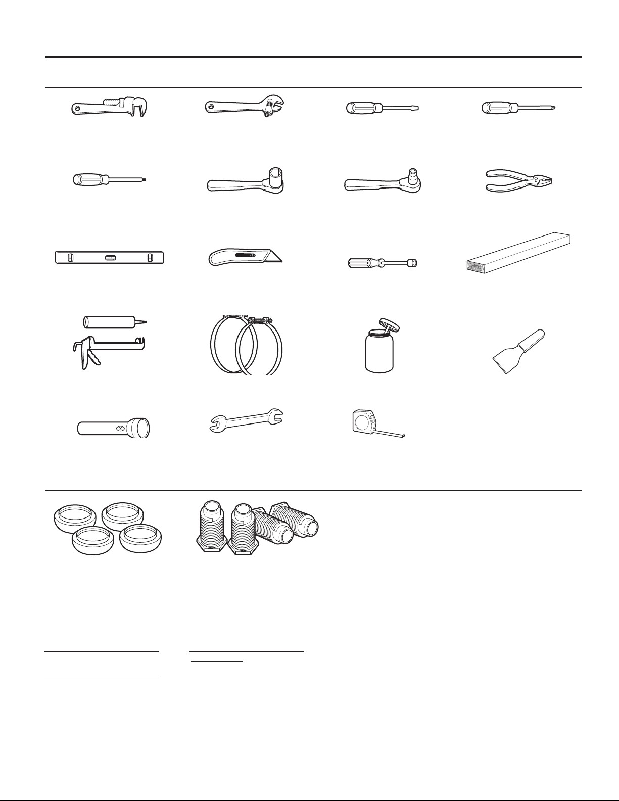
TOOLS & PARTS
Tools Needed:
203 mm (8") 203 mm (8") or 254 mm (10") Flat-Blade Screwdriver Phillips Screwdriver
or 254 mm (10") Adjustable Wrench
Pipe Wrench that opens to 25 mm ( 1")
Torx† T-20† Security 25 mm (1") Hex-Head 8 mm ( 5⁄16") Socket Wrench Pliers (that open to
Screwdriver or Bit Socket Wrench 39 mm [19/16"])
Level Utility Knife 6 mm (1/4") Nut Driver 686 mm (27")
Wood Block
Caulk Gun and Caulk Vent Clamps Pipe-Joint Compound Putty Knife
(for installing new exhaust vent) Suitable for Gas Type
Flashlight (optional) 25 mm (1") Ruler or Measuring Tape
Open-End Wrenches
Parts Supplied:
Foot Boots (4) Leveling Legs (4)
NOTE: The circuit diagram for this dryer is located inside the
lower front panel, within the Tech Sheets.
Electric Model:
Technical Specications:
220 – 240 V, 50 Hz. AC
4575W
Total mass: 68 kg max.
Clothes Capacity:
IEC Capacity
9 kg
NOTE: Sound Pressure Level, LpA: 58 dB(A)
[uncertainty, KpA: +/–10 dB(A)].
†TORX and T20 are trademarks of Acument Intellectual Properties, LLC.
7

DIMENSIONS/CLEARANCES
Dimensions
Side View Back View
Clearances
35"
(889 mm)
1"
(25 mm)
(743 mm)
(660 mm)
1
/2"
7
(191 mm)
291/4"
26"
1
8
/4"
(210 mm)
31/4"
(83 mm)
11/2"
(38 mm)
5
(140 mm)
1
(343 mm)
/2"
(343 mm)
131/2"
Gas
13
(686 mm)
Electric
1
/2"
27"
(273 mm)
4" dia
(102 mm)
103/4
"
(83 mm)
(914 mm)
(electric models)
31/4"
Front View, Recessed Opening Side View, Recessed In Closet
36"
(953 mm)
(gas models)
371/2"
41"
(1042 mm)
14" max
(356 mm)
(0 mm)
14" max
(356 mm)
3"/3"
(76 mm)
15"
(381 mm)
0"
0"
0"
(0 mm)
(0 mm)
0"
(0 mm)
0"
(0 mm)
15"
(381 mm)
1"
(25 mm)
Closet Door to
Front of Dryer
3"/3"
(76 mm)
2
48"
/48"
(310 cm2)
2/
24"
24"
(155 cm2)
2
2
8

DRYER INSTALLATION REQUIREMENTS
(155 cm
)
Location Requirements
Your dryer can be installed in a basement, laundry room, or
recessed area.
This dryer is not intended for installation in a mobile home.
Companion appliance location requirements should also be
considered.
IMPORTANT: Do not install or store the dryer where it will be
exposed to water and/or the weather. Proper installation is your
responsibility.
You will need:
■ A grounded electrical outlet located within 6 ft. (1.8 m) of
where the power cord is attached to the back of the dryer.
See “Electrical Requirements.”
■ A level oor with a maximum slope of 1" (25 mm) under
entire dryer. Installing the dryer on soft oor surfaces,
such as carpets or surfaces with foam backing, is not
recommended.
Gas dryer installation clearances
■ The location must be large enough to allow the dryer door to
be fully opened.
■ Additional spacing should be considered for ease of
installation and servicing. The door opens more than 180°.
■ Additional clearances might be required for wall, door, and
oor moldings.
■ Additional spacing of 1" (25 mm) on all sides of the dryer is
recommended to reduce noise transfer.
When installing a gas dryer:
IMPORTANT: Observe all governing codes and ordinances.
■ Check code requirements: Some codes limit or do not
permit installation of clothes dryers in garages, closets, or
sleeping quarters. Contact your local building inspector.
■ Make sure that lower edges of the cabinet, plus the back
and bottom sides of the dryer, are free of obstructions to
permit adequate clearance of air openings for combustion
air. See “Recessed Area and Closet Installation Instructions”
below for minimum spacing requirements.
Recessed Area and Closet Installation Instructions
This dryer may be installed in a recessed area or closet. For
recessed area and closet installations, minimum clearances
can be found on the warning label on the rear of the dryer
or in “Dimensions/Clearances.”
The installation spacing is in inches and is the minimum
allowable. Additional spacing should be considered for ease
of installation, servicing, and compliance with local codes and
ordinances.
If closet door is installed, the minimum unobstructed air
opening in the top and bottom is required. The unobstructed
opening needs to be 1 square inch per 1,000 Btu (252 kcal)
of gas burner output. Output on North American gas dryers
is typically 22,000 Btu; however, Canadian dryers may have
lower output. Louvered doors with equivalent air openings are
acceptable.
The dryer must be exhausted outdoors.
No other fuel-burning appliance may be installed in the same
closet as the dryer.
2
48 in.
(310 cm2)
Front
Front
View
View
2
24 in.
2
Closet
Closet
Door
door
)
3"
(76 mm)
3"
(76 mm
9
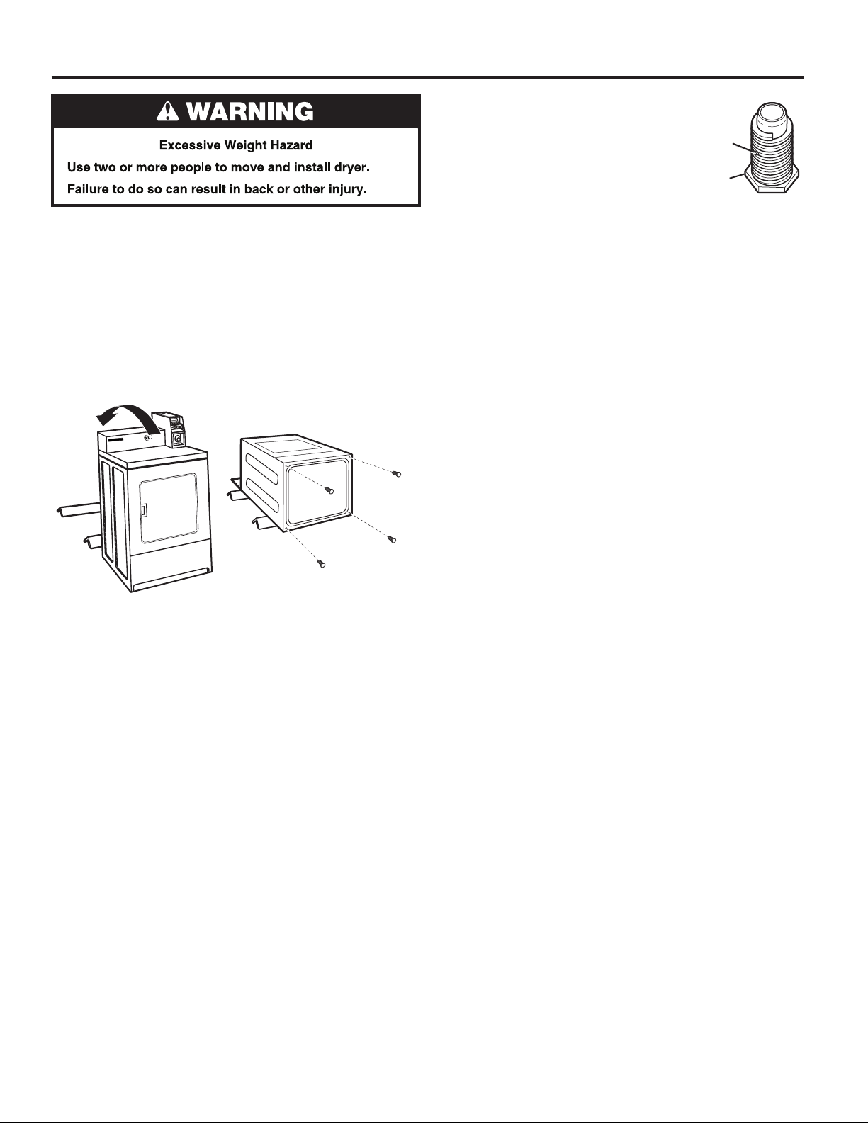
INSTALLING LEVELING LEGS
1. Prepare dryer for leveling legs
NOTE: Slide dryer onto cardboard or hardboard before moving
to avoid damaging oor covering.
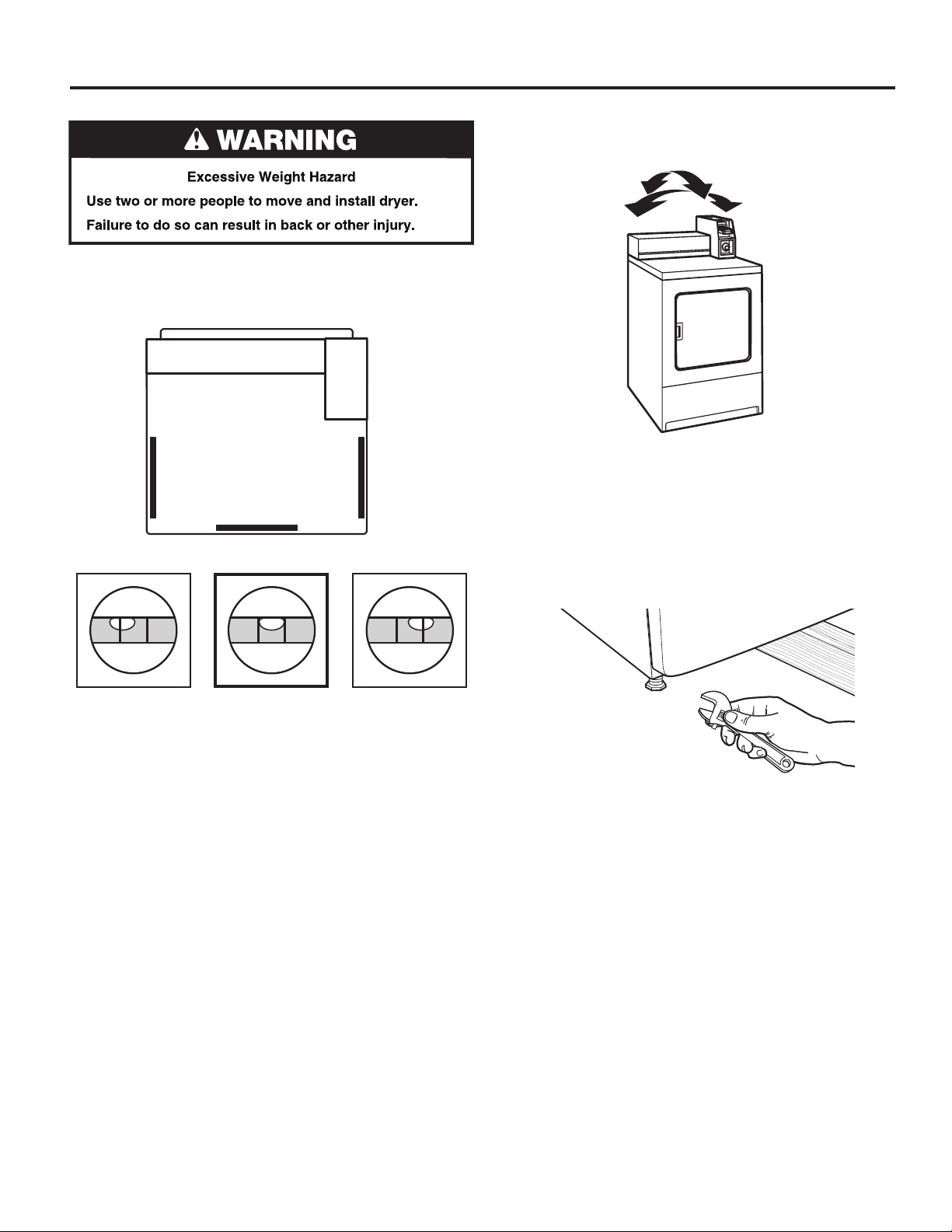
Using two or more people, move dryer to desired installation
location.
Take tape off front corners of dryer. Open dryer and remove
the literature and parts packages. Wipe drum interior with a
damp cloth to remove any dust.
Take two cardboard corners from the dryer carton and place
them on the oor in back of the dryer. Firmly grasp the body of
the dryer and gently lay it on its back on the cardboard corners.
2. Screw in leveling legs
Examine leveling legs and nd diamond
marking. Screw legs into leg holes by
hand. Use an adjustable wrench or
25 mm (1") hex-head socket wrench
to nish turning legs until diamond
marking is no longer visible. Then t
a covered foot boot over each leg foot.
To protect the oor, use a large piece of cardboard from the
dryer carton. Stand dryer up on the cardboard. Slide the dryer
until it is close to its nal location. Leave enough room for
electrical connection and to connect the exhaust vent.
A longer leveling foot is available if needed on extremely sloped
oors, Part Number 279810.
Diamond
Marking
Foot
10
LEVELING
Leveling your dryer properly reduces excess noise and vibration.
1. Remove cardboard from beneath dryer. Place a level on top
edges of dryer, checking each side and front. If not level,
tip dryer and adjust legs up or down as shown in Step 3,
repeating as necessary.
(appearance may vary)
2. Grip dryer from top and rock back and forth, making sure all
four legs are rmly on oor. Repeat, rocking dryer from side
to side. If dryer rocks, go to Step 3 and adjust leveling legs.
(appearance may vary)
3. If dryer is not level, use a 1" or 25 mm open-end or
adjustable wrench to turn the leveling leg counterclockwise
to lower the dryer or clockwise to raise the dryer. Recheck
levelness of dryer and that all four legs are rmly in contact
with the oor. Repeat as needed.
HELPFUL TIP: You may want to prop up front of dryer about
4" (102 mm) with a wood block or similar object that will
support weight of dryer.
Not Level LEVEL Not Level
11
ELECTRIC DRYER INSTALLATION REQUIREMENTS
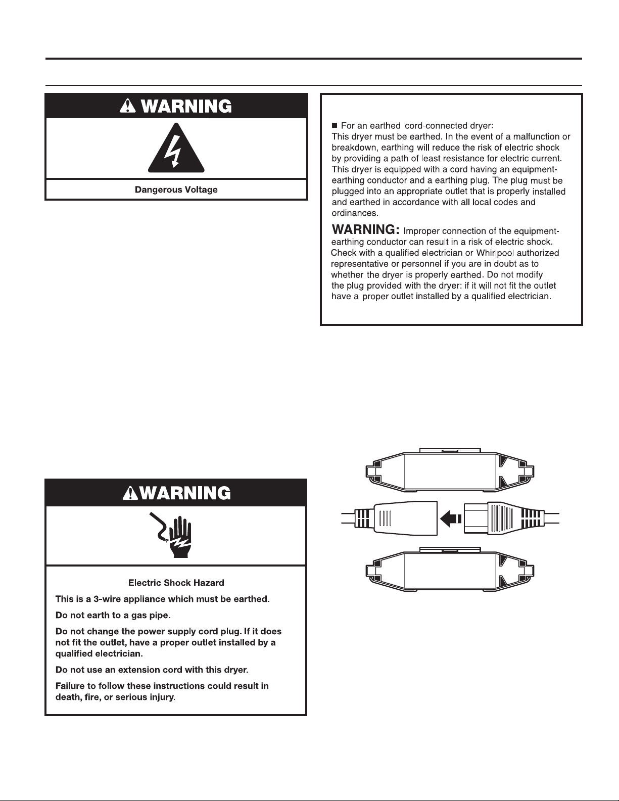
Electrical Requirements
Electric Shock Hazard
This dryer is supplied without an electric cord and plug. It
must be connected by a Whirlpool authorized service person
to a single-phase electricity supply at the voltage shown
on the dataplate, using a suitable xed wiring installation in
accordance with local and national wiring regulations.
■ A 3-wire circular cord of minimum conductor size 2.5 mm2
cross-section area should be used.
■ A 25A (minimum) supply fuse should be used, and a
switch with a clear OFF marking having a contact
separation in both poles that provides full disconnection
under over-voltage category III conditions must be
incorporated into the xed wiring in accordance with local
wiring regulations by a competent electrician. The dryer
should be positioned so that the disconnection switch
is clearly visible and easily accessible to the user. This
disconnection switch also provides the function of an
emergency stop control for the user.
■ A cord clamp bush is provided on the dryer, and should
be tightened on completion of wiring. The electrical mains
terminals are located behind the small rear access panel
(terminal block cover), and connections should be made
in accordance with the terminal markings. Remember to
replace the terminal access panel (terminal block cover).
NOTE: In accordance with the European EMC Directive
(2004/108/EC), the maximum electrical supply system
impedance to which the electric dryer should be connected
is declared to be 0.054 Ohm + j0.034 Ohm.
NOTE: Electrical safety standards: The manufacturer has
chosen compliance with IEC/EN.60335 standards as the most
appropriate for this product.
This is 3-wire appliance which must be earthed.
Do not earth to a gas pipe.
Failure to follow these instructions could result in
death, re, or serious injury.
If codes permit and an additional ground bond wire is used, it
is recommended that a qualied electrician determine that the
ground bond path is adequate.
Recommended Earthing Method
It is your responsibility to contact a qualied electrical installer
to ensure that the electrical installation is adequate and in
conformance with all local codes and ordinances.
12
GAS DRYER INSTALLATION REQUIREMENTS
Electrical Requirements
IMPORTANT: Observe all governing codes and ordinances.
You will need a grounded electrical outlet located within
610 mm (2 feet) of either side of the dryer.
This dryer is supplied/tted with an electrical supply cord and
plug. It should be connected to electrical supply socket at
the voltage shown on the rating plate. The minimum supply
fuse capacity should be 10A. The dryer must be positioned so
that the plug is clearly visible and accessible. This plug also
provides the function of an emergency stop control for the user.
If the tted plug is not used, the electrical connection must be
carried out by a competent electrician in accordance with local
or national codes.
If the supply cord is damaged, it must be replaced with a
specially terminated cord by an authorized service agent
or a similarly competent person in order to avoid a hazard.
Do not use an adapter.
Do not use an extension cord.
NOTE: In accordance with the European EMC Directive
(2004/108/EC), the maximum electricity supply system
impedance to which the gas dryer should be connected is
declared to be 0.29 Ohm + j0.18 Ohm.
NOTE: Electrical safety standards: The manufacturer has
chosen compliance with IEC/EN.60335 standards as the most
appropriate for this product.
EARTHING INSTRUCTIONS
SAVE THESE INSTRUCTIONS
Using the universal cord included with this dryer:
The gas dryer is equipped with a universal cord with
interchangeable plugs.
1. To use the universal cord, select the plug end that ts your
electrical outlet, and plug it into the adapter on the supply
cord.
2. Secure the plug end in place on the cord by aligning the
2 cover halves over the cord adapter and clipping them
together.
If codes permit and an additional ground bond wire is used, it
is recommended that a qualied electrician determine that the
ground bond path is adequate.
13

GAS DRYER INSTALLATION REQUIREMENTS
Gas Supply
Supply line requirements:
Provide a rigid gas supply line to the dryer location. It should
be minimum 12.5 mm (1/2") ID. When acceptable to the gas
supplier and local codes, 10 mm (3/8") ID rigid supply line may
be used for lengths under 6.1 m (20'). Pipe-joint compounds
resistant to the action of L.P. gas must be used.
NOTE: For installation in Australia and New Zealand, refer to
AS/NZS 5601 for pipe sizing details. All piping is to be in
accordance with AS/NZS 5601.1 – Gas Installations.
Gas connection to the dryer itself should be made by means
of a exible gas hose suitable for the appliance and gas
category in accordance with national installation regulations.
If in doubt, contact the gas supplier. It should be minimum
10 mm (3/8") ID.
A means of restraint should be used between the dryer and the
wall to avoid straining of the rigid gas supply when the dryer
is moved. An appropriate length of chain and a wall hook is
recommended.
The dryer gas inlet connection is a 10 mm (3/8") NPT thread.
An adapter is supplied for conversion to standard ISO.228-1
thread (10 mm [3/8"] BSP).
IMPORTANT: Observe all governing codes and ordinances.
In Australia and New Zealand, refer to AS/NZS 5601.1 – Gas
Installations.
Gas Supply
Before installation, check that the local gas distribution
conditions, nature of gas and pressure, and the adjustment of
the appliance are compatible. Burner information will be found
on the model/serial rating plate in the door recess of the dryer.
If this information does not agree with the type of gas available,
see your dealer.
Natural Gas:
This dryer is factory adjusted for use with NATURAL GAS (G20),
and no further adjustment should be required at installation.
L.P. Gas:
This dryer is also certied for use with L.P. (propane or butane)
gases with appropriate conversion. No attempt shall be made
to convert the appliance from the gas specied on the model/
serial rating plate for use with a different gas without consulting
the serving gas supplier.
Conversion must be done by a Whirlpool authorized service
technician. Gas conversion kit (European Country), part number
W10233219, is available for purchase from your dealer. Gas
conversion kit (Australia), part number W10315369, is available
for purchase from your dealer. Full instructions are supplied
with the kit.
Natural Gas (France/Belgium):
This dryer is also certied for France/Belgium for use with G20/
G25 gases (20 mbar/25 mbar) with appropriate conversion. No
attempt should be made to convert this appliance from the gas
specied on the gas rating label for use with a different gas
without consulting the serving gas supplier. Gas conversion
must be done by a Whirlpool authorized gas service technician.
Conversion kit, part number (W10181947) is available for
purchase from your dealer. Full instructions are supplied with
the kit.
Check for leaks by using an approved noncorrosive leakdetection solution. Bubbles will show a leak. Correct any leak
found. A pressure measurement tapping is provided on the gas
valve within the dryer, accessible after removal of the lower
front panel.
The dryer must be disconnected from the gas supply piping
system during any pressure testing of that system.
14

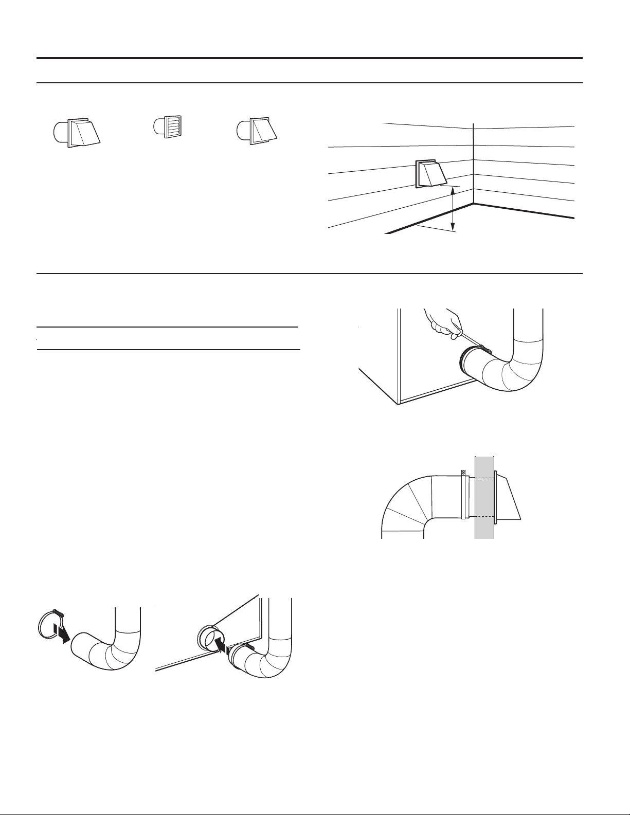
DRYER VENTING REQUIREMENTS
Elbows:
■ 45° elbows provide better airow than 90° elbows.
WARNING: To reduce the risk of re, this dryer MUST BE
EXHAUSTED OUTDOORS.
IMPORTANT: Observe all governing codes and ordinances.
In Australia and New Zealand, refer to AS/NZS 5601.1 – Gas
Installations.
Dryer exhaust must not be connected into any gas vent,
chimney, wall, ceiling, attic, crawlspace, or a concealed space
of a building. Only rigid or exible metal vent shall be used for
exhausting.
102 mm
(4")
Good
Better
Clamps:
■ Use clamps to seal all joints.
■ Exhaust vent must not be connected or secured with screws
or other fastening devices that extend into interior of duct
and catch lint. Do not use duct tape.
102 mm (4") Heavy, Metal Exhaust Vent
■ Only a 102 mm (4") heavy, metal exhaust vent and clamps
may be used.
■ Do not use plastic or metal foil vent.
Rigid metal vent:
■ Recommended for best drying performance and to avoid
crushing and kinking.
Flexible metal vent: (Acceptable only if accessible to clean)
■ Must be fully extended and supported in nal dryer location.
■ Remove excess to avoid sagging and kinking that may result
in reduced airow and poor performance.
■ Do not install in enclosed walls, ceilings, or oors.
■ The total length should not exceed 2.4 m (7
3
⁄4 ft.).
NOTE: If using an existing vent system, clean lint from entire
length of the system and make sure exhaust hood is not
plugged with lint. Replace plastic or metal foil vents with rigid
metal or exible metal vents. Review “Vent System Chart” and,
if necessary, modify existing vent system to achieve best drying
performance.
15
DRYER VENTING REQUIREMENTS
Vent Hoods
102 mm (4") Diameter Exhaust Hoods
Exhaust hood must be at least 305 mm (12") from the ground
or any object that may be in the path of the exhaust (such as
owers, rocks, bushes, or snow).
Box Hood Louvered Hood Angled Hood
Vent System Length
Maximum Vent Length/Vent Connection
Maximum length of vent system depends upon the type of vent
used, number of elbows, and type of exhaust hood.
Vent System Chart (Rigid Metal Vent)
No. of Box and Angled
90˚ Turns Louvered Hood Hood
0 39.6 m (130 ft.) 39.3 m (129 ft.)
1 38.1 m (125 ft.) 36.3 m (119 ft.)
2 35.1 m (115 ft) 33.2 m (109 ft.)
3 32.3 m (106 ft.) 30.5 m (100 ft.)
4 29.9 m (98 ft.) 28.0 m (92 ft.)
For vent systems not covered by the vent specication chart,
see your parts distributor.
Provision must be made for enough air for combustion and
ventilation. (Check governing codes and ordinances.) See
“Recessed Area and Closet Installation Instructions” in the
“Location Requirements” section.
A 102 mm (4") outlet hood is preferred. However, a 64 mm
(21⁄2") outlet exhaust hood may be used. A 64 mm (21⁄2") outlet
creates greater back pressure than other hood types. For
permanent installation, a stationary vent system is required.
Connect Vent
1. If connecting to existing vent, make sure the vent is clean.
2. Using a 102 mm (4") clamp, connect vent to exhaust outlet
in dryer.
Vent Collar
305 mm min.
12" min.
(305 mm)
(12")
3. Tighten hose clamp with Phillips screwdriver.
4. Make sure the vent is secured to exhaust hood with
a 102 mm (4") clamp.
5. Move dryer into nal position. Do not crush or kink vent.
Make sure dryer is level.
NOTE: Testing for proper ventilation should be done with a
Manometer. Minimum: 0.01" (0.2 mm). Maximum: 0.6" (16 mm).
NOTE: Do not remove vent collar.
16
DRYER VENTING REQUIREMENTS
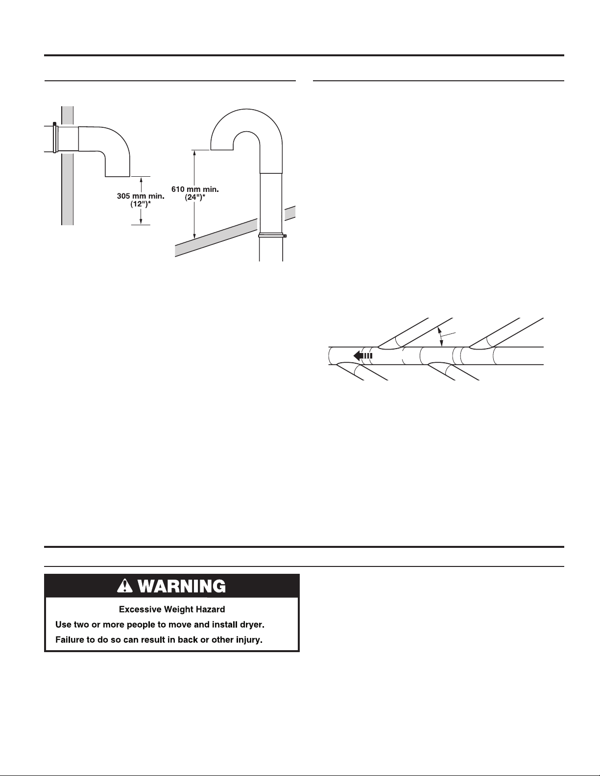
If an Exhaust Hood Cannot be Used Multiple Dryer Venting
The outside end of main vent should have a sweep elbow
directed downward.
* Minimum clearance above any
accumulation of snow, ice, or
debris such as leaves
If main vent travels vertically through the roof, rather than
through wall, install a 180° sweep elbow on end of vent at least
610 mm (2 ft.) above surface of roof.
The opening in wall or roof shall have a diameter 13 mm (1⁄2")
larger than vent diameter. Vent should be centered in opening.
Do not install screening over end of vent for best performance.
A main vent can be used for venting a group of dryers. The
main vent should be sized to remove 5663 l/min. (200 CFM) of
air per dryer. Large-capacity lint screens of proper design may
be used in main vent if checked and cleaned frequently. The
room where the dryers are located should have make-up air
equal to or greater than CFM of all the dryers in the room.
Back-draft dampers are available from your distributor and
should be installed in the vent of each dryer to keep exhausted
air from returning into dryers and to keep exhaust in balance
within main vent. Unobstructed return air openings are required.
Although usually each single-load dryer should have an
unobstructed outdoor air opening of 154 cm2 (24 in.2) (based
on 6.5 cm2 [1 in.2] per 252 kcal [1,000 Btu]), common make-up
air openings are also acceptable. Set up common openings so
the make-up air is distributed equally to all of the dryers. Keep
in mind that the coverage area must be increased by 33% to
account for the use of registers or louvers over the openings.
Also, make-up air openings should not be installed near the
location where exhaust vents exit the building.
Each vent should enter the main vent at an angle pointing in
the direction of the airow. Vents entering from the opposite
side should be staggered to reduce the exhausted air from
interfering with the other vents.
Air Flow
Air ow
30˚ max.
GAS SUPPLY CONNECTION (on some models)
Make Gas Connection
1. Connect gas supply to dryer. If the exible gas hose has
10 mm (3/8") BSP thread, use the supplied conversion
thread adapter. Use pipe-joint compound resistant to the
action of L.P. gas for gas connections.
If necessary for service, open the toe panel. Use a putty
knife to press on the 2 toe panel locks located at the top
of the toe panel. Pull downward on the toe panel to open.
Toe panel is hinged at the bottom.
The maximum angle of each vent entering the main vent should
be no more than 30°.
Keep air openings free of dry cleaning uid fumes. Fumes
create acids which, when drawn through the dryer heating
units, can damage dryers and items being dried.
A clean-out cover should be located on the main vent for
periodic cleaning of the vent system.
NOTE: For more dryer venting information, please refer to
Whirlpool document W10100920.
2. Open the shut-off valve in the gas supply line and make sure
the dryer has its own gas supply opened.
3. Test all connections by brushing on an approved
noncorrosive leak-detection solution. Bubbles will show
a leak. Correct any leaks found.
17
TECHNICAL SPECIFICATIONS – GAS DRYER
220–240V~50Hz 1ph 3A max. IP24 Clothes capacity: 9.0 kg max. Sound pressure level, Lpa: 58 dBA (uncertainty, Kpa: +/-10 dBA) Total mass: 68 kg max.
Factory set for NATURAL GAS: Injector size: 2.2 mm Heat input gross: 5.9 kW
Country: CH, CZ, CY, ES, GB, GR,
HR, IE, IT, PT, SI, SK, TR
European Gas Category:
Gas Flow Rate: .562703 m3/hr 0.562703 m3/hr
Supply Pressure (G20): 20 mbar 20 mbar
Factory Adjusted Pressure: 7.4 mbar 7.4 mbar
With LP Gas Conversion Kit: Injector size: 1.25 mm Heat input gross: 6.4 kW
European Country: CH, CZ, CY, ES, GB, GR, HR,
European Gas Category:
Butane Supply Pressure (G30): 28–30 mbar 30 mbar
Adjusted Pressure: N/A N/A
Propane Supply Pressure (G31): 37 mbar 30 mbar
Adjusted Pressure: N/A N/A
With France/Belgium NATURAL GAS conversion kit: Injector size 1.65 mm Heat input gross: 5.9 kW
European Country: FR, BE
European Gas Category:
Supply Pressure (G20): 20 mbar
Supply Pressure (G25): 25 mbar
Adjusted Pressure: N/A
II
2H3+
IE, IT, PT, SI, SK, TR
II
2H3+
I
2E+
CY, CZ, DK, EE, FI, GR, HU,
IT, NO, RO, SE, SK, TR
II
2H3B/P
CY, CZ, DK, EE, FI, GR, HU,
IT, NO, RO, SE, SK, TR
II
2H3B/P
Factory set for Australia/New Zealand NATURAL GAS: Injector size: 2.2 mm Heat input gross: 5.9 kW
Country: AS, NZS
Supply Pressure (G20) minimum 1.13 kPa
Adjusted Pressure (Test Point Pressure): 0.74 kPa
Nominal Hourly Gas Consumption 21.1 MJ/h
With Australia LG Gas Conversion Kit: Injector Size: 1.40 mm Heat input gross: 6.54 kW
Country: AS, NZS
Propane Supply Pressure: 2.75 kPa
Adjusted Pressure: 2.75 kPa
Nominal Hourly Gas Consumption: 23 MJ/h
Factory set for NATURAL GAS: Injector size: 2.2 mm Heat input gross: 5.0 kW
Country: NL
European Gas Category:
Gas Flow Rate: 0.562703 m3/hr
Supply Pressure (G25): 25 mbar
Factory Adjusted Pressure (G25) : 7.4 mbar
Supply Pressure (G30/G31): 30 mbar
Factory Adjusted Pressure (G30/G31): N/A
NOTE: Conversion kit: From Natural Gas to LP Gas - Europe: Whirlpool Part No. W10233219.
Conversion kit: From Natural Gas to LP Gas - Australia: Whirlpool Part No. W10315369.
Conversion kit: From Natural Gas to Natural Gas - France/Belgium: Whirlpool Part No. W10181947.
Manufacturer: Whirlpool Corporation, Benton Harbor, Michigan 49022, U.S.A.
Manufacturing Site: Whirlpool Corporation, 1300 Marion-Agosta Rd., Marion, OH, 43302, U.S.A.
EU Representative: Whirlpool Europe s.r.l. Viale Guido Borghi 27, 21025 Comerio (VA) Italy
II
2L3B/P
18
COMPLETE INSTALLATION
1. Check the electrical requirements. Be sure that you have
the correct electrical supply and the recommended earthing
method. See “Electrical Requirements.”
2. Check that all parts are now installed. If there is an extra part,
go back through the steps.
3. Check that you have all of your tools.
4. Dispose of/recycle all packaging materials.
WARNING
Electric Shock Hazard
This dryer must be earthed.
Securely tighten all electrical connections.
Failure to do so can result in death, fire, or
electric shock.
5. Plug into a grounded outlet, or connect power.
6. Check dryer operation (some accumulated time may be
on the timer due to factory testing). Close dryer door. Insert
coins in slide and press slide in slowly. (Operating time will
accumulate per number of coins and type of timing cam
used.) Push START button. Using a full heat cycle (not the
air cycle), let the dryer run for at least ve minutes. Dryer will
stop when time is used up.
NOTE: Dryer door must be closed for dryer to operate.
When door is open, dryer stops, but timer continues to run.
To restart dryer, close door and push START button.
7. Gas models only: Open the dryer door. Check that the
inside of the dryer is warm. If the burner does not ignite and
you can feel no heat inside the dryer, shut off dryer for ve
minutes. Check that all supply valve controls are in “ON”
position and that the electrical cord is plugged in. Repeat
ve-minute test.
8. If drying time is too long, make sure that the lint screen is
clean and that there are no obstructions to airow in the
dryer vent system.
9. Restart the dryer and allow it to complete a full heat cycle
(not air cycle) to make sure it is working properly.
19
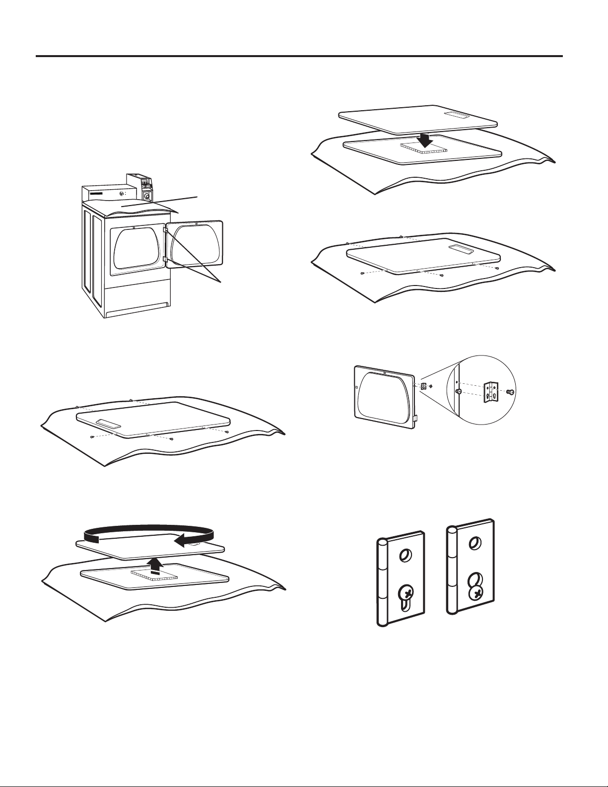
REVERSING DRYER DOOR SWING (OPTIONAL)
You can change your door swing from a right-side opening
to left-side opening, if desired.
Remove the Door Assembly
1. Place a towel or soft cloth on top of dryer or work space to
avoid scratching of the surface.
2. Open dryer door. Remove bottom screws from cabinet side
of hinges. Loosen (do not remove) top screws from cabinet
side of hinges.
Towel
Hinges
3. Lift door until top screws in cabinet are in large part of hinge
slot. Pull forward off screws. Set door (handle side up) on
top of dryer. Remove top screws from cabinet.
4. Remove screws attaching hinges to door.
5. Remove screws at top, bottom, and side of door (5 screws).
7. Be certain to keep cardboard spacer centered between
doors. Reattach outer door panel to inner door panel so
handle is on the side where hinges were just removed.
8. Reattach screws at top, bottom, and side of door (5 screws).
9. Attach door hinges to dryer door so that larger hole is at the
bottom of the hinge and the hinge pin is toward the door
front.
6. Holding door over towel on dryer, grasp sides of outer door
and gently lift to separate it from inner door. Do not use a
putty knife to pry apart. Do not pull on door seal or plastic
door catch.
10. Remove the 4 screws that attach 2 plugs on the left side.
Attach plugs to right side using the same 4 screws.
11. Insert screws into bottom holes on left side of cabinet.
Tighten screws halfway. Position door so large end of door
hinge slot is over screws. Slide door up so screws are in
bottom of slots. Tighten screws. Insert and tighten top
screws in hinges.
12. Close door and check that door strike aligns with door
catch. If needed, slide door catch left or right within slot to
adjust alignment.
20

MODEL NOMENCLATURE:
CGM – Whirlpool Gas FQ – Series Revision
CEM – Whirlpool Electric 2765 – Model Type Number
DRYER DISPOSAL
21

WHIRLPOOL COMMERCIAL LAUNDRY
LIMITED WARRANTY
IF YOU NEED SERVICE:
Contact your authorized Whirlpool Commercial Laundry distributor. To locate your authorized Whirlpool Commercial Laundry distributor,
visit www.WhirlpoolCommercialLaundry.com.
For written correspondence:
Whirlpool Commercial Laundry Service Department
2000 N M 63
Benton Harbor, Michigan 49022-2632 USA
THREE YEAR LIMITED WARRANTY
WHAT IS COVERED
THREE YEAR LIMITED WARRANTY
(PARTS ONLY — LABOR NOT INCLUDED)
For the first three years from the original date of
purchase, when this commercial appliance is installed,
maintained, and operated according to the instructions
attached to or furnished with the product, Whirlpool
Corporation (hereafter “Whirlpool”) will pay for factory
specified replacement parts to correct defects in
materials or workmanship that existed when this
commercial appliance was purchased. This limited
warranty does not include labor.
YOUR SOLE AND EXCLUSIVE REMEDY UNDER THIS
LIMITED WARRANTY SHALL BE PRODUCT REPAIR
AS PROVIDED HEREIN. Whirlpool recommends that
you use an “authorized” service provider to diagnose
and repair your Commercial Laundry product.
Whirlpool will not be responsible under this warranty
to provide additional replacement parts as a result
of incorrect diagnosis or repair by an “unauthorized”
service company. Except in the European Union, this
limited warranty is valid only when the commercial
appliance is used in the country in which it was
purchased. This limited warranty is effective from
the date of the original consumer purchase. Proof
of original purchase date is required to obtain service
under this limited warranty.
IMPLIED WARRANTIES, INCLUDING ANY IMPLIED WARRANTY OF MERCHANTABILITY OR IMPLIED WARRANTY OF FITNESS FOR A
PARTICULAR PURPOSE, ARE LIMITED TO THREE YEARS OR THE SHORTEST PERIOD ALLOWED BY LAW. Some locations may not allow
limitations on the duration of implied warranties of merchantability or fitness, so this limitation may not apply to you. This warranty gives you
specific legal rights, and you also may have other rights that vary.
DISCLAIMER OF REPRESENTATIONS OUTSIDE OF WARRANTY
Whirlpool makes no representations about the quality, durability, or need for service or repair of this major appliance other than the
representations contained in this Warranty. If you want a longer or more comprehensive warranty than the limited warranty that comes
with this major appliance, you should ask your retailer about buying an extended warranty. The benefits to you given by this warranty
are in addition to other rights and remedies available to you under a law in relation to the goods or service to which this warranty relates.
Please contact Whirlpool for further information on warranty terms.
LIMITATION OF REMEDIES; EXCLUSION OF INCIDENTAL AND CONSEQUENTIAL DAMAGES
YOUR SOLE AND EXCLUSIVE REMEDY UNDER THIS LIMITED WARRANTY SHALL BE PRODUCT REPAIR AS PROVIDED HEREIN.
WHIRLPOOL SHALL NOT BE LIABLE FOR INCIDENTAL OR CONSEQUENTIAL DAMAGES. Some locations do not allow the exclusion or
limitation of incidental or consequential damages, so these limitations and exclusions may not apply to you. This warranty gives you specific
legal rights, and you also may have other rights that vary by location.
04/17
1. All other costs including labor, transportation, shipping, or custom duties for
covered parts.
2. Factory specified replacement parts if this commercial appliance is used for other
than normal, commercial use or when it is used in a manner that is inconsistent
to published user or operator instructions and/or installation instructions.
3. Service calls to correct the installation of your commercial appliance, to instruct
you on how to use your commercial appliance, to replace or repair house fuses,
or to correct external wiring or plumbing.
4. Service calls to repair or replace appliance light bulbs, air filters, or water filters.
Consumable parts are excluded from warranty coverage.
5. Damage resulting from improper handling of product during delivery, theft,
accident, alteration, misuse, abuse, fire, flood, acts of God, improper installation,
installation not in accordance with local electrical or plumbing codes, or use of
products not approved by Whirlpool.
6. Pick up and delivery. This commercial appliance is designed to be repaired
on location.
7. Repairs to parts or systems resulting from unauthorized modifications made
to the commercial appliance.
8. The removal and reinstallation of your commercial appliance if it is installed
in an inaccessible location or is not installed in accordance with published
installation instructions.
9. Damage resulting from exposure to chemicals.
10. Changes to the building, room, or location needed in order to make the
commercial appliance operate correctly.
11. Factory specified replacement parts on commercial appliances with original
model/serial numbers that have been removed, altered, or cannot be easily
determined.
12. Discoloration, rust, or oxidation of stainless steel surfaces.
13. Factory specified replacement parts as a result of incorrect diagnosis or repair
by an “unauthorized” service company.
The cost of repair or replacement under these excluded circumstances shall
be borne by the customer.
DISCLAIMER OF IMPLIED WARRANTIES
WHAT IS NOT COVERED
22

SECURITE DU SECHE-LINGE
AVERTISSEMENT – “Risque d’incendie”
Ceci est un symbole supplémentaire d’alerte de sécurité vous signalant un risque d’incendie.
AVERTISSEMENT
- L'installation du sèche-linge et la maintenance doivent être réalisées par un installateur
agréé par Whirlpool.
- Installer le sèche-linge conformément aux instructions du fabricant et aux
réglementations locales.
- Ne pas installer de sèche-linge avec des évents en plastique exible ou un conduit
en métal exible (de type papier aluminium). Si un conduit en métal est installé,
il doit être d'un type spécique identié par le fabricant de l'appareil comme adapté
à l'utilisation avec des sèche-linge. On sait que les évents en matériaux exibles ont
tendance à se plier, s'écraser facilement et retenir la charpie. Ces conditions niront
par obstruer le ux d'air du sèche-linge et augmenteront le risque d'incendie.
- Pour réduire le risque de blessures graves ou de mort, respecter toutes les
instructions d'installation.
- Conserver ces instructions.
-
“Risque d'incendie”
23

SECURITE DU SECHE-LINGE
■ On recommande que le propriétaire place les instructions à l’usage du client en un lieu bien visible, au cas où le client percevrait
une odeur de gaz. Ces renseignements doivent être obtenus auprès de votre fournisseur en gaz.
■ Placer l’avertissement qui suit à un endroit bien visible.
POUR VOTRE SECURITE
1. NE PAS UTILISER OU REMISER D’ESSENCE OU AUTRES MATÉRIAUX INFLAMMABLES DANS CET APPAREIL MÉNAGER
O U À PROXIMITÉ DE CELUI-CI.
2. NE PAS VAPORISER D’AÉROSOLS À PROXIMITÉ DE CET APPAREIL MÉNAGER LORSQU’IL EST EN FONCTIONNEMENT.
3. NE PAS MODIFIER CET APPAREIL MÉNAGER.
AVERTISSEMENT : pour votre sécurité, les informations contenues dans ce manuel
doivent être respectées afin de réduire les risques d'incendie ou d'explosion et d'éviter
les dommages aux propriétés, les blessures ou les décès.
–
Ne pas utiliser ou conserver d’essence ni d'autres vapeurs et liquides inflammables
à proximité de cet appareil électrique ou de tout autre.
–
QUE FAIRE SI VOUS DÉTECTEZ UNE ODEUR DE GAZ :
Ne pas essayer d'allumer d'appareil.
•
Ne pas toucher d'interrupteur électrique ; ne pas utiliser de téléphone dans le bâtiment.
•
Faire sortir tous les occupants de la pièce, du bâtiment ou de la zone.
•
Appeler immédiatement votre fournisseur de gaz à partir du téléphone d'un voisin.
•
Suivre les instructions du fournisseur de gaz.
S'il est impossible de joindre le fournisseur de gaz, appeler les pompiers.
•
– L'installation et la maintenance doivent être réalisées par un installateur ou une agence
agréés par Whirlpool ou par le fournisseur de gaz.
IMPORTANT : Pour mettre l’ancien sèche-linge au rebut ou pour le remiser, enlever la porte.
24

SECURITE DU SECHE-LINGE
IMPORTANTES INSTRUCTIONS DE SÉCURITÉ
AVERTISSEMENT : Pour réduire les risques d’incendie, de choc électrique ou de blessures lors de l’utilisation
du sèche-linge, suivre les précautions fondamentales dont les suivantes :
■ Lire toutes les instructions avant d’utiliser
le sèche-linge.
■ Ce sèche-linge est conçu uniquement pour le séchage
de vêtements et de textiles ayant été nettoyés à l’eau. Ne
pas l’utiliser à d'autres ns.
■ AVERTISSEMENT: Si l’on détecte une odeur de gaz,
ne pas utiliser le sèche-linge ou tout autre équipement
électrique situé à proximité. Avertir les autres personnes
qu’elles doivent évacuer cette zone. Contacter le
propriétaire du sèche-linge immédiatement.
■ Ne pas placer des articles exposés aux huiles de cuisson
dans votre sèche-linge. Les articles contaminés par des
huiles de cuisson peuvent contribuer à une réaction
chimique qui pourrait provoquer l'inammation de la
charge.
■ Si on doit absolument placer des tissus qui contiennent
de l’huile végétale ou de cuisson ou qui ont été
contaminés par des produits de soin capillaire dans
un sèche-linge, il faut d’abord les laver dans de l’eau
chaude avec un supplément de détergent; ceci réduira
le danger, sans toutefois l’éliminer.
■ Ne pas faire sécher des articles qui ont été nettoyés
ou lavés avec de l’essence ou imbibés d’essence, de
solvants de nettoyage à sec ou d’autres substances
inammables ou explosives ; ces substances peuvent
émettre des vapeurs susceptibles de s’enammer ou
d’exploser.
■ Les articles qui ont été souillés avec des substances
comme de l’acétone, de l’alcool, du pétrole, du kérosène,
des détachants, de la térébenthine, des cires et des
décapants pour cire doivent être lavés à l’eau chaude
avec un supplément de détergent avant d’être séchés
dans le sèche-linge.
■ Ne pas faire sécher dans le sèche-linge des
articles non lavés.
■ Ne pas utiliser ce sèche-linge si l’on a utilisé des
produits chimiques industriels pour le nettoyage.
La présence éventuelle de quantités résiduelles de
produits chimiques corrosifs ou décomposés dans
la charge peut endommager le sèche-linge et produire
des fumées toxiques.
■ Ne pas laisser d’enfants jouer sur, dans ou avec le
sèche-linge. Bien surveiller les enfants lorsque le
sèche-linge est utilisé à proximité d’enfants.
■ Ce sèche-linge n’est pas conçu pour une utilisation
par des personnes (notamment des enfants) aux
capacités physiques, sensorielles ou mentales réduites,
ou manquant d’expérience ou de connaissances, à
moins qu’elles soient supervisées par une personne
responsable ou aient reçu des instructions adaptées
pour utiliser le sèche-linge en toute sécurité.
■ Avant de retirer le sèche-linge du service ou de le mettre
au rebut, ôter la porte du compartiment du sèche-linge.
■ Ne pas insérer une partie du corps dans la cuve du
sèche-linge lorsque le tambour est en mouvement.
■ Ne pas ouvrir la porte lorsque le sèche-linge est
en marche. Il s’arrêtera.
■ L'appareil doit être débranché de sa source
d'alimentation pendant le service et lors du
remplacement des pièces.
■ Lors du chargement ou du rechargement du sèche-linge,
éviter de toucher les parties métalliques chaudes du
tambour (risque de brûlure).
■ Vériez que les poches des vêtements à sécher ne
contiennent pas d'objets tels que des briquets ou
des allumettes.
■ Les opérations de nettoyage et d'entretien par
l'utilisateur ne doivent pas être réalisées par des
enfants non surveillés.
■ AVERTISSEMENT : L’appareil ne doit pas être mis
sous tension via un dispositif de commutation externe,
tel qu'un minuteur, ni être connecté à un circuit
régulièrement mis sous tension et hors tension par un
utilitaire.
■ Évitez d'installer le sèche-linge derrière une porte
verrouillable, une porte coulissante ou une porte dont
les charnières se trouvent sur le côté opposé à celui de
la charnière de la porte du sèche-linge, de façon que
l'ouverture complète de cette dernière ne soit pas gênée.
■ L’appareil est conçu pour être utilisé dans des lieux
publics, sans toutefois être limité à une telle utilisation.
■ Les enfants de moins de 3 ans doivent être tenus à
distance de l'appareil ou être surveillés en permanence.
■ Si la rotation du tambour est entravée par des tissus
coincés, déconnecter le sèche-linge de l’alimentation
électrique avant de retirer la source d’obstruction avec
précaution.
■ Ne pas utiliser le sèche-linge s’il ne chauffe pas,
s’il semble défectueux ou endommagé. Contacter
le propriétaire.
■ Ne pas installer ou remiser ce sèche-linge à un endroit
où il serait exposée aux intempéries.
■ Ne pas modier les organes de commande.
■ Nettoyer le ltre à charpie avant et après chaque charge.
■ Ne pas utiliser ce sèche-linge si le ltre à peluches
n’est pas installé.
■ Ne pas réparer ou remplacer un composant quelconque
du sèche-linge, ni entreprendre une opération de
service, si ce n’est spéciquement recommandé
dans ce manuel ou dans un manuel d’instructions
de réparations destiné à l’utilisateur; il est alors essentiel
que la personne concernée comprenne ces instructions
et soit compétente pour les exécuter.
■ Les assouplissants et autres produits similaires doivent
être utilisés conformément aux instructions gurant sur
l'emballage.
■ Ne séchez pas au sèche-linge des articles en caoutchouc
mousse (mousse de latex), des bonnets de douche, des
articles imperméables ou au revers caoutchouté, ni des
vêtements ou des oreillers dont le rembourrage est en
caoutchouc mousse.
■ La dernière partie d’un programme de séchage
par culbutage a lieu sans chaleur (programme de
refroidissement) pour faire en sorte que les articles
soient laissés à une température qui garantit que les
articles ne seront pas endommagés.
CONSERVEZ CES INSTRUCTIONS
25

IMPORTANTES INSTRUCTIONS DE SÉCURITÉ
AVERTISSEMENT : Pour réduire les risques d’incendie, de choc électrique ou de blessures lors de l’utilisation
du sèche-linge, suivre les précautions fondamentales dont les suivantes :
■ AVERTISSEMENT: Ne jamais arrêter le séchage par
culbutage avant la n du programme de séchage sauf
si tous les articles sont retirés rapidement et étendus
pour une dissipation de la chaleur (permet d’éviter le
risque de combustion spontanée).
■ En cas de coupure de l’alimentation électrique, retirer
rapidement la charge et l’étaler pour éviter tout risque
de combustion spontanée.
■ Ne pas laisser la charpie, la poussière, ou la saleté
s’accumuler autour du système d’évacuation ou autour
de l’appareil.
■ Les ouvertures de ventilation pour l’arrivée d’air frais
dans la pièce et dans le sèche-linge ne doivent pas être
obstruées ou scellées.
■ Commande d’arrêt d’urgence : Après l'installation,
l'accès à la prise secteur (sèche-linge à gaz) ou à
l'alimentation secteur (sèche-linge électrique) via un
interrupteur bipolaire doit être maintenu à tout moment
pour assurer une désactivation immédiate du sèche-linge
en cas d'urgence.
■ L’intérieur du sèche-linge et de son conduit d’évacuation
doit être nettoyé périodiquement par un technicien
d’entretien agréé par Whirlpool.
■ Voir la section “Spécications électriques” pour les
instructions de mise à la terre.
■ Une ventilation adéquate doit être prévue pour éviter que
les gaz ne retournent dans la pièce à partir d'appareils
brûlant des combustibles, y compris des feux nus.
CONSERVEZ CES INSTRUCTIONS
INSTRUCTIONS D’ENTRETIEN
■ Nettoyer le ltre à charpie avant ou après chaque
programme.
■ Comment enlever la charpie accumulée:
À l’intérieur de la caisse de le sèche-linge:
Retirer la charpie tous les 2 ans, ou plus souvent, selon
l’utilisation de le sèche-linge. Le nettoyage doit être réalisé
par une personne agréée par Whirlpool.
De l’intérieur du conduit d’évacuation:
Retirer la charpie tous les 2 ans, ou plus souvent, selon
l’utilisation de le sèche-linge.
■ Dégager l’espace autour de le sèche-linge; les matières
combustibles, à base de pétrole et les autres liquides ou
vapeurs inammables ne doivent pas s’y trouver.
■ Dégager l’emplacement de le sèche-linge de façon à ce qu’il
soit libre de tout élément susceptible d’obstruer le débit
d’air de combustion et de ventilation.
Si le sèche-linge ne fonctionne pas, vérifier ce qui suit:
■ La prise de courant est correctement alimentée.
■ Le disjoncteur ne s’est pas déclenché et aucun fusible n’est
grillé.
■ La porte est fermée. Écouter attentivement pour vérier que
le loquet de porte s’enclenche.
■ Les commandes sont réglées à la position de marche ou
« ON » (marche).
■ On a appuyé fermement sur le bouton START (mise en
marche).
■ Pour les sécheuses à gaz, vérier que le robinet d’arrêt est
ouvert.
AVERTISSEMENT: Un raccordement inapproprié du conducteur de liaison à la terre peut causer
un risque de choc électrique. Il incombe à l’utilisateur de vérier avec un électricien qualié ou avec un
représentant de service en cas de doute quant à la qualité de la liaison à la terre de l’appareil et pour savoir si
elle répond aux codes et règlements locaux. Ne pas modier la che fournie avec cette sécheuse: si elle ne
correspond pas à la prise de sortie, faire installer une che appropriée par un électricien qualié.
SI VOUS AVEZ BESOIN D’ASSISTANCE
Pour toute assistance, communiquer avec le marchand auprès duquel l’appareil a été acheté ou une compagnie de réparation
désignée par Whirlpool. Avant d’appeler, vous devez connaître la date d’achat et les numéros de modèle et de série complets
de votre appareil. Ces renseignements nous aideront à mieux répondre à votre demande.
POUR CONTACTER LE SERVICE APRÈS-VENTE:
Adressez-vous à votre distributeur Whirlpool Commercial Laundry agréé. Pour identier le distributeur Whirlpool Commercial
Laundry agréé le plus proche, consultez le site Internet www.WhirlpoolCommercialLaundry.com.
Pour écrire au service après-vente, ulisez cee adresse :
Whirlpool Commercial Laundry Service Department
2000NM63
Benton Harbor, Michigan 49022-2632, États-Unis
26
 Loading...