

Whirlpool XCEM2763BQ, XCGM2763BQ Installation Instructions

INSTALLATION INSTRUCTIONS
CommerCial Gas or
moDels XCem2763 anD XCGm2763
eleCtriC
Dryer
INSTRUCTIONS D’INSTALLATION
sèChe-linGe À Gaz ou
moDèles XCem2763 et XCGm2763
éleCtrique
À usaGe CommerCial
INSTRUCCIONES DE INSTALACIÓN
seCaDora a Gas o
moDelos XCem2763 y XCGm2763
eléCtriCa
ComerCiale
ISTRUZIONI D’INSTALLAZIONE
asCiuGatriCe a Gas o
moDelli XCem2763 e XCGm2763
elettriCa
CommerCiale
www.whirlpoolcommerciallaundry.comW10474285A

TABLE OF CONTENTS
Page
Dryer Safety ............................................................................. 3
Dryer Disposal ........................................................................ 6
Tools & Parts ........................................................................... 7
Dimensions/Clearances ........................................................ 8
Dryer Installation Requirements .......................................... 9
Electric Dryer Installation Requirements .......................... 10
Gas Dryer Installation Requirements ................................. 11
Dryer Venting Requirements .............................................. 13
Gas Supply Connection ...................................................... 15
Installing Leveling Legs ....................................................... 16
Leveling ................................................................................. 17
Complete Installation ........................................................... 18
Reversing Dryer Door Swing ............................................... 19
Maintenance Instructions .................................................... 20
If You Need Assistance ........................................................ 20
Technical Specications – Gas Dryer ................................. 21
Warranty ................................................................................ 22
ÍNDICE
Página
Seguridad de la secadora ..................................................... 43
Eliminación de la secadora ................................................. 46
Herramientas y piezas ......................................................... 47
Dimensiones y espacios libres ........................................... 48
Requisitos de instalación de la secadora ......................... 49
Requisitos de instalación de la secadora eléctrica ......... 50
Requisitos de instalación de la secadora a gas ............... 51
Requisitos de ventilación de la secadora ......................... 53
Conexión del suministro de gas ......................................... 56
Instalación de las patas niveladoras .................................. 57
Nivelación .............................................................................. 58
Complete la instalación ....................................................... 59
Cómo invertir el sentido de apertura de la puerta ............. 60
Instrucciones de mantenimiento ........................................ 61
Si necesita ayuda ................................................................. 61
Especicaciones técnicas – secadora a gas ..................... 61
Garantía ................................................................................. 62
TABLE DES MATIÈRES
Page
Sécurité du sèche-linge ...................................................... 23
Élimination du sèche-linge ................................................ 26
Outils et pièces ................................................................... 27
Dimensions/Distances de dégagement ........................... 28
Exigences d’installation pour le sèche-linge .................... 29
Exigences d’installation pour le sèche-linge électrique .. 30
Exigences d’installation pour le sèche-linge à gaz .......... 31
Exigences concernant l’évacuation
du sèche-linge .................................................................... 33
Raccordement à la canalisation de gaz ........................... 35
Installation des pieds de nivellement ............................... 36
Nivellement .......................................................................... 37
Achever l’installation ........................................................... 38
Inversion du sens d’ouverture de la porte ........................ 39
Instructions d’entretien ....................................................... 40
Si vous avez besoin d’assistance ...................................... 40
Fiche technique – sèche-linge à gaz ................................. 41
Garantie ................................................................................ 42
INDICE
Pagina
Sicurezza dell’asciugatrice ................................................... 63
Eliminazione dell’asciugatrice ............................................. 66
Attrezzi e componenti .......................................................... 67
Dimensioni/spazi ................................................................. 68
Requisiti dell’installazione dell’asciugatrice ..................... 69
Requisiti dell’installazione dell’asciugatrice elettrico ...... 70
Requisiti dell’installazione dell’asciugatrice a gas ........... 71
Requisiti di scarico dell’asciugatrice ................................. 73
Collegamento di alimentazione del gas ............................ 75
Installazione dei piedini di regolazione .............................. 76
Livellamento .......................................................................... 77
Completamento dell’installazione ...................................... 78
Invertire il senso di apertura dello sportello ...................... 79
Istruzioni di manutenzione ................................................... 80
Se avete bisogno dell’assistenza ........................................ 80
Dati tecnici – asciugatrice a gas ......................................... 81
Garanzia ................................................................................ 83
2
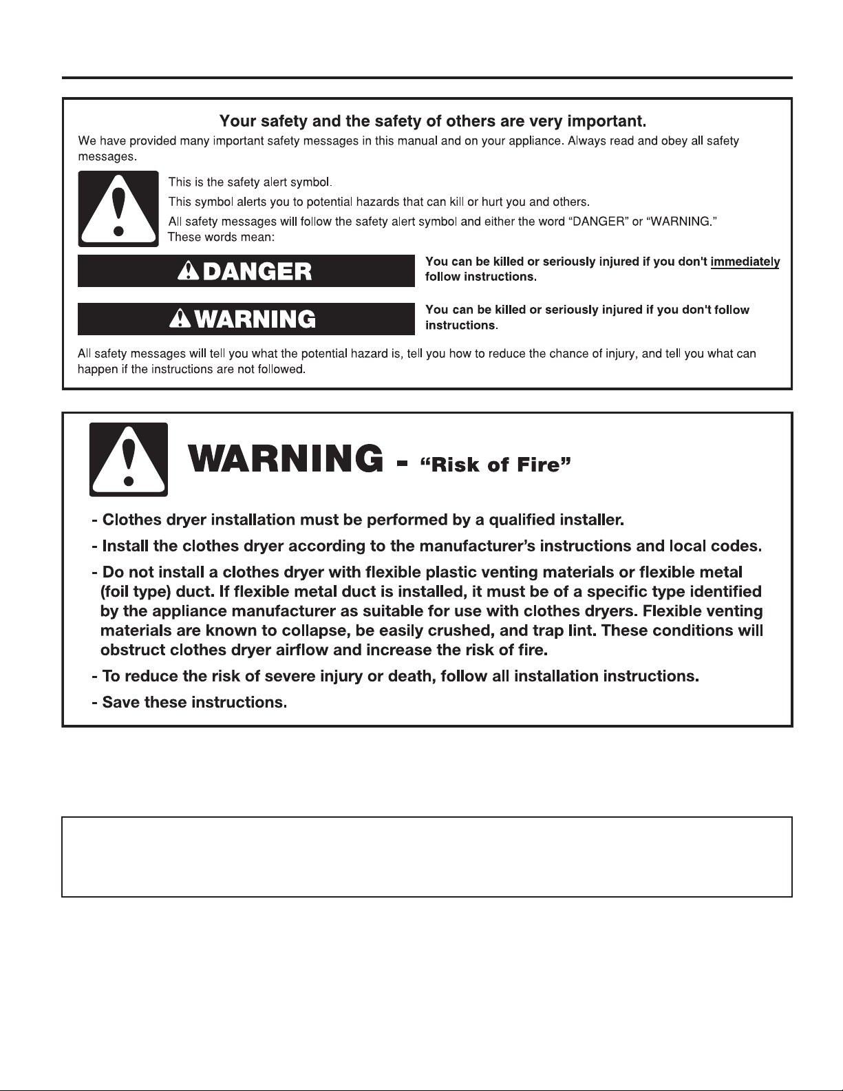
DRYER SAFETY
■ It is recommended that the owner post, in a prominent location, instructions for the customer’s use in the event the customer
smells gas. This information should be obtained from your gas supplier.
■ Post the following warning in a prominent location.
FOR YOUR SAFETY
1. DO NOT USE OR STORE PETROL OR OTHER FLAMMABLE MATERIALS IN THIS APPLIANCE OR NEAR THIS APPLIANCE.
2. DO NOT SPRAY AEROSOLS IN THE VICINITY OF THIS APPLIANCE WHILE IT IS IN OPERATION.
3. DO NOT MODIFY THIS APPLIANCE.
3
DRYER SAFETY
IMPORTANT: When discarding or storing your old clothes dryer, remove the door.
4

DRYER SAFETY
IMPORTANT SAFETY INSTRUCTIONS
WARNING: To reduce the risk of re, electric shock, or injury to persons when using the dryer, follow basic precautions,
including the following:
■ Read all instructions before using the dryer.
■ This dryer is intended only for drying clothes and textiles
that have been washed in water. Do not use for any
other purpose.
■ WARNING: If you smell gas, do not use the dryer or any
electrical equipment nearby. Warn other people to clear
the area. Contact the dryer owner immediately.
■ Do not place items exposed to cooking oils in your dryer.
Items contaminated with cooking oils may contribute to
a chemical reaction that could cause a load to catch re.
■ If it is unavoidable that fabrics that contain vegetable or
cooking oil or that have been contaminated by hair care
products be placed in a tumble dryer, they should rst
be washed in hot water with extra detergent – this will
reduce, but not eliminate the hazard.
■ Do not dry articles that have been previously cleaned
in, washed in, soaked in, or spotted with petrol,
dry-cleaning solvents, other ammable, or explosive
substances as they give off vapors that could ignite
or explode.
■ Items that have been soiled with substances such
as acetone, alcohol, petrol, kerosene, spot removers,
turpentine, waxes, and wax removers should be washed
in hot water with extra detergent before being dried
in the dryer.
■ Do not dry unwashed items in the dryer.
■ Do not use this dryer if industrial chemicals have been
used for cleaning. The possible presence of residual
quantities of aggressive or decomposed chemicals in
the load may produce damage to the dryer and harmful
fumes.
■ Do not allow children to play on or in the dryer. Close
supervision of children is necessary when the dryer is
used near children.
■ This dryer is not intended for use by persons (including
children) with reduced physical, sensory, or mental
capabilities, or lack of experience or knowledge,
unless they have been given supervision or instruction
concerning use of the dryer by a person responsible for
their safety.
■ Before the dryer is removed from service or discarded,
remove the door to the dryer compartment.
■ Do not reach into the dryer if the drum is moving.
■ Do not open door while dryer is in operation. It will stop.
■ When loading or re-loading the dryer, avoid touching hot
metal parts of the drum (burn risk).
■ If drum rotation is blocked due to trapped textiles,
disconnect the dryer from the electrical supply before
gently removing the blockage.
■ If the dryer is not heating, or appears to be defective or
damaged, do not use it. Contact the owner.
■ Do not install or store the dryer where it will be exposed
to the weather.
■ Do not tamper with controls.
■ Clean dryer lint screen before or after each load.
■ Do not use this dryer without the lint screen in place.
■ Do not repair or replace any part of the dryer or attempt
any servicing unless specically recommended in this
Installation Instructions or in published user-repair
instructions that you understand and have the skills
to carry out.
■ Do not use fabric softeners or products to eliminate static
unless recommended by the manufacturer of the fabric
softener or product.
■ Do not use heat to dry articles containing foam rubber or
similarly textured rubber-like materials.
■ The nal part of a tumble dryer cycle occurs without
heat (cool-down cycle) to ensure that the articles are left
at a temperature that ensures that the items will not be
damaged.
■ WARNING: Never stop a tumble dryer before the end of
the drying cycle unless all items are quickly removed and
spread out so that the heat is dissipated. (Avoids risk of
spontaneous combustion).
■ In case of electrical supply failure, remove the load
quickly and spread it out to avoid risk of spontaneous
combustion.
■ Keep area around the exhaust opening and adjacent
surrounding areas free from the accumulation of lint, dust,
and dirt.
■ The fresh air ventilation openings into the room and into
the dryer must not be blocked or sealed.
■ Emergency stop control: The mains plug should be
removed in an emergency.
■ The interior of the dryer and dryer exhaust vent should
be cleaned periodically by qualied service personnel.
■ See “Electrical Requirements” section for earthing
instructions.
SAVE THESE INSTRUCTIONS
5
DRYER DISPOSAL
MODEL NOMENCLATURE:
CGM – Whirlpool Gas CS – Coin Operated
CEM – Whirlpool Electric MN – Non-Pay
2763 – Model Type Number
6
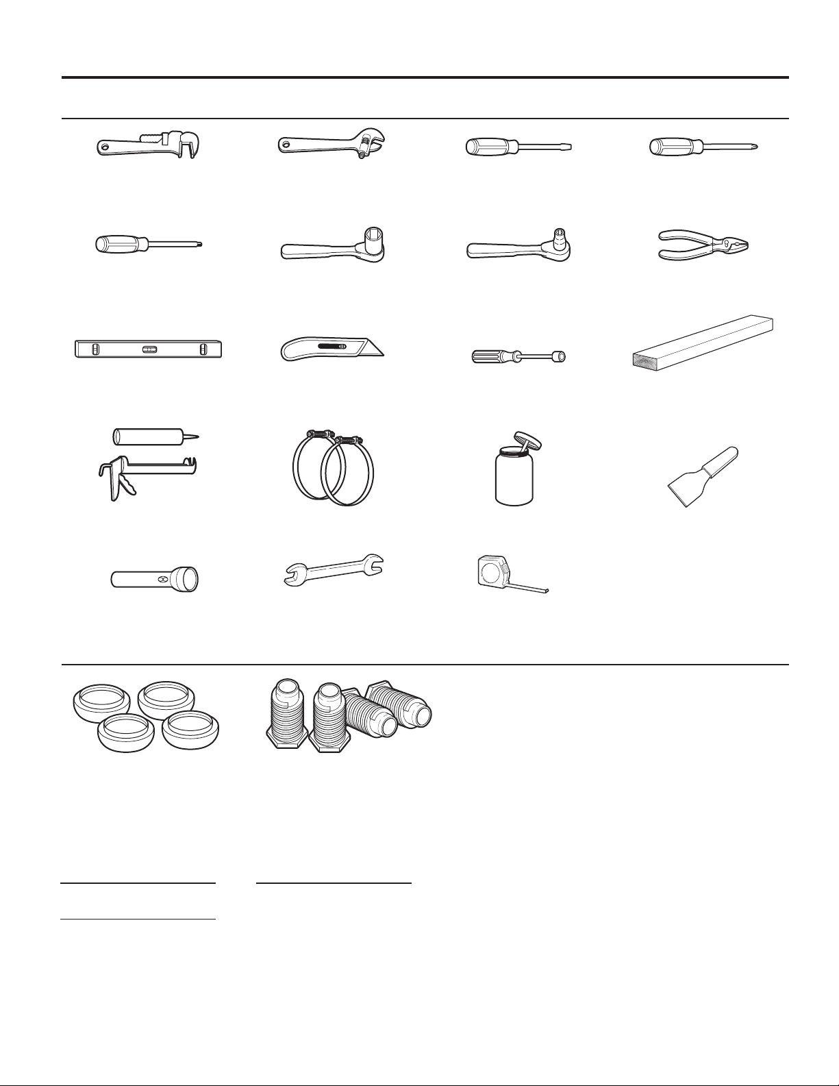
TOOLS & PARTS
Tools Needed:
203 mm (8") 203 mm (8") or 254 mm (10") Flat-Blade Screwdriver Phillips Screwdriver
or 254 mm (10") Adjustable Wrench
Pipe Wrench that opens to 25 mm ( 1")
Torx®† T-20®† Security 25 mm (1") Hex-Head 8 mm ( 5⁄16") Socket Wrench Pliers (that open to
Screwdriver or Bit Socket Wrench 39 mm [19/16"])
Level Utility Knife 6 mm (1/4") Nut Driver 686 mm (27")
Wood Block
Caulk Gun and Caulk Vent Clamps Pipe-Joint Compound Putty Knife
(for installing new exhaust vent) Suitable for Gas Type
Flashlight (optional) 25 mm (1") Ruler or Measuring Tape
Open-End Wrenches
Parts Supplied:
Foot Boots (4) Leveling Legs (4)
NOTE: The circuit diagram for this dryer is located inside the
lower front panel, within the Tech Sheets.
Electric Model:
Technical Specications:
220 – 240 V, 50 Hz. AC
4575W
Total mass: 68 kg max.
Clothes Capacity:
9 kg max.
NOTE: Sound Pressure Level, Lpa: 58 dBA
(uncertainty, Kpa: +/–10 dBA).
†® TORX and T20 are registered trademarks of Acument Intellectual Properties, LLC.
7
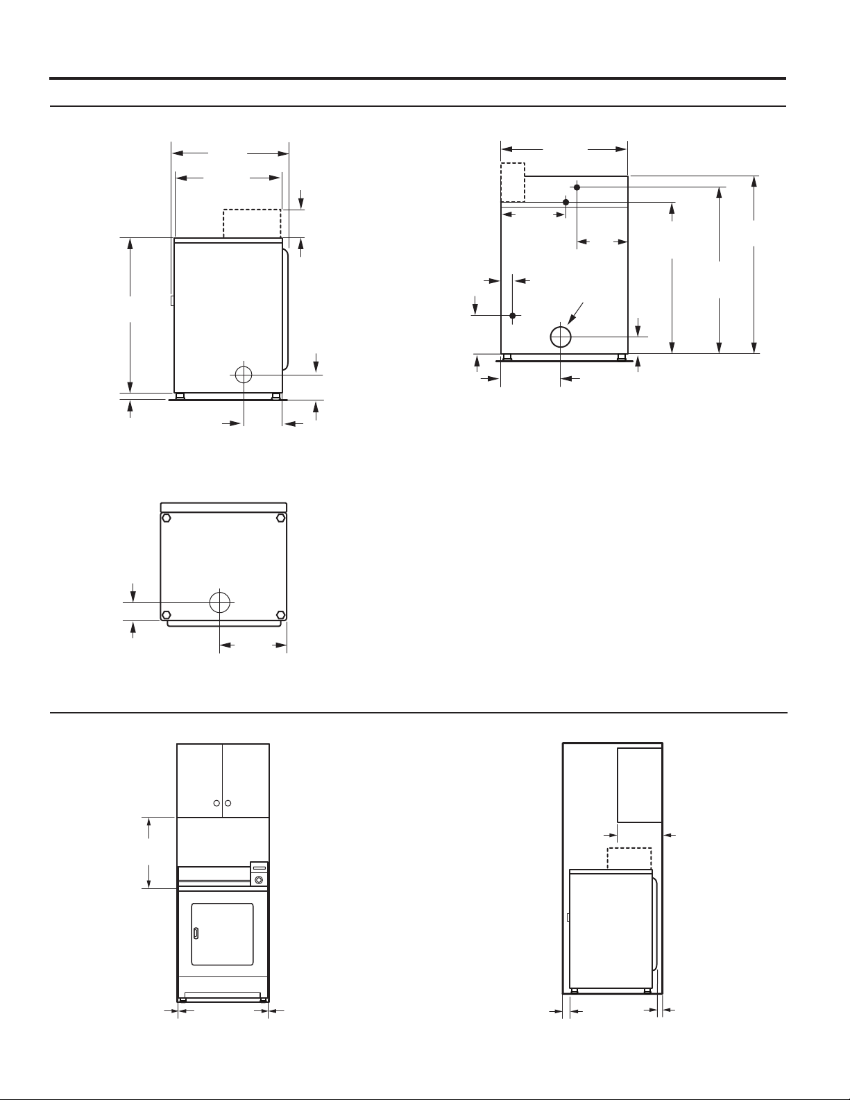
DIMENSIONS/CLEARANCES
Dimensions
Side View Back View
889 mm
(35")
743 mm
(291/4")
648 mm
(251/2")
210 mm
1
(8
/4")
83 mm
(31/4")
38 mm
1
(1
/2")
140 mm
(5
1
/2")
686 mm
(27")
Electric
343 mm
(131/2")
Gas
279 mm
(11")
102 mm
(4" dia)
889 mm
(35")
(electric models)
940 mm
(37")
(gas models)
1048 mm
1
(41
/4")
25 mm
(1")
260 mm
1
/4")
(10
330 mm
(13")
83 mm
(31/4")
Bottom Exhaust
178 mm
(7")
359 mm
1
(14
/8")
Clearances
Recessed Front View Closet Side View
381 mm
(15")
0 mm
(0")
0 mm
(0")
25 mm
(1")
356 mm
(14")
0 mm
(0")
8
DRYER INSTALLATION REQUIREMENTS
(Australia and New Zealand – for full details of installation requirements refer to AS/NZS 5601.1)
Location Requirements
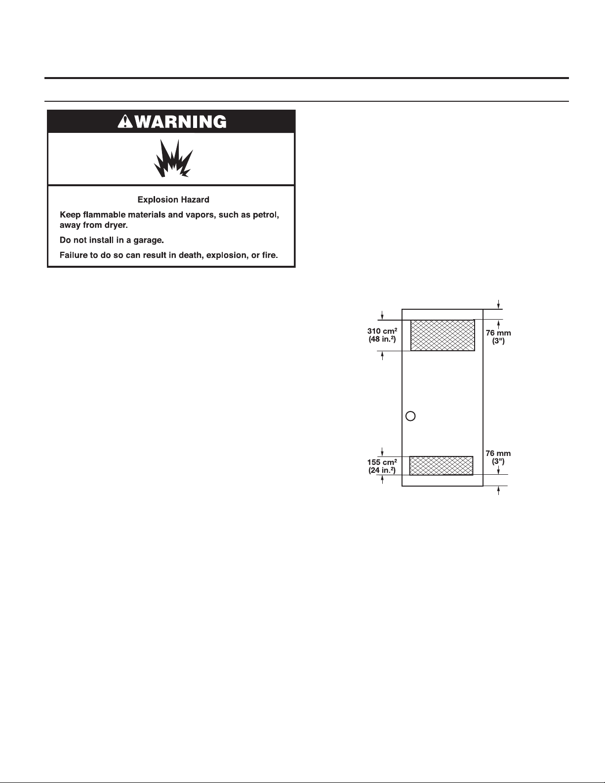
Recessed Area and Closet Installation Instructions
This dryer may be installed in a recessed area or closet. For
recessed area and closet installations, minimum clearances
can be found on the warning label on the rear of the dryer
or in “Dimensions/Clearances.”
The installation spacing is in millimeters and is the minimum
allowable. Additional spacing should be considered for ease
of installation, servicing, and compliance with local codes and
ordinances.
If closet door is installed, the minimum unobstructed air
opening in the top and bottom is required. Louvered doors
with equivalent air openings are acceptable.
The dryer must be exhausted outdoors.
No other fuel-burning appliance may be installed in the same
closet as the dryer.
Your dryer can be installed in a basement, laundry room,
or recessed area.
This dryer is not intended for installation in a mobile home.
Companion appliance location requirements should also be
considered.
IMPORTANT: Do not install or store the dryer where it
will be exposed to the weather. Proper installation is your
responsibility.
You will need:
■ An earthed electrical outlet located within 1.8 m (6 ft.) of
where the power cord is attached to the back of the dryer.
See “Electrical Requirements.”
■ A level oor with a maximum slope of 25 mm (1") under
entire dryer. Installing the dryer on soft oor surfaces,
such as carpets or surfaces with foam backing, is not
recommended.
Dryer installation clearances
■ The location must be large enough to allow the dryer door
to be fully opened.
■ Additional spacing should be considered for ease of
installation and servicing. The door opens more than 180°.
■ Additional clearances might be required for wall, door, and
oor moldings.
■ Additional spacing of 25 mm (1") on all sides of the dryer
is recommended to reduce noise transfer.
When installing a dryer:
IMPORTANT: Observe all governing codes and ordinances.
■ Check code requirements: Some codes limit or do not
permit installation of clothes dryers in garages, closets,
or sleeping quarters. Contact your local building inspector.
NOTE: For installation in Australia and New Zealand,
install dryer in accordance with AS/NZS 5601.1 and local
governance codes.
■ Gas Dryers only: Make sure that lower edges of the
cabinet, plus the back and bottom sides of the dryer, are
free of obstructions to permit adequate clearance of air
openings for combustion air. See “Recessed Area and
Closet Installation Instructions” below for minimum
spacing requirements.
NOTE: For installation in Australia and New Zealand, refer to
AS/NZS 5601.1 for ventilation requirements.
Front
View
Closet
Door
9
ELECTRIC DRYER INSTALLATION REQUIREMENTS
Electrical Requirements
This dryer is supplied without an electric cord and plug. It must
be connected by a competent electrician to a single-phase
electricity supply at the voltage shown on the dataplate, using
a suitable xed wiring installation in accordance with local and
national wiring regulations.
■ A 3-wire circular cord of minimum conductor size 2.5 mm2
cross-section area should be used.
■ A 25A (minimum) supply fuse should be used, and a switch
having a contact separation in both poles that provides full
disconnection under over-voltage category III conditions
must be incorporated into the xed wiring in accordance
with local wiring regulations. The dryer should be positioned
so that the disconnection switch is clearly visible and easily
accessible to the user. This disconnection switch also
provides the function of an emergency stop control for
the user.
■ A cord clamp bush is provided on the dryer, and should
be tightened on completion of wiring. The electrical mains
terminals are located behind the small rear access panel
(terminal block cover), and connections should be made
in accordance with the terminal markings. Remember to
replace the terminal access panel (terminal block cover).
NOTE: In accordance with the European EMC Directive
(2004/108/EC), the maximum electrical supply system
impedance to which the electric dryer should be connected
is declared to be 0.054 Ohm + j0.034 Ohm.
NOTE: Electrical safety standards: The manufacturer has
chosen compliance with IEC/EN.60335 standards as the most
appropriate for this product.
This is 3-wire appliance which must be earthed.
If codes permit and an additional earth bond wire is used, it is
recommended that a qualied electrician determine that the
earth bond path is adequate.
Recommended Earthing Method
It is your responsibility to contact a qualied electrical installer
to ensure that the electrical installation is adequate and in
conformance with all local codes and ordinances.
10
GAS DRYER INSTALLATION REQUIREMENTS
Electrical Requirements
IMPORTANT: Observe all governing codes and ordinances.
You will need an earthed electrical outlet located within
610 mm (2 feet) of either side of the dryer.
This dryer is supplied/tted with an electrical supply cord and
plug. It should be connected to electrical supply socket at
the voltage shown on the rating plate. The minimum supply
fuse capacity should be 10A. The dryer must be positioned so
that the plug is clearly visible and accessible. This plug also
provides the function of an emergency stop control for the user.
If the tted plug is not used, the electrical connection must be
carried out by a competent electrician in accordance with local
or national codes.
If the supply cord is damaged, it must be replaced with a
specially terminated cord by an authorized service agent
or a similarly competent person in order to avoid a hazard.
Do not use an adapter.
Do not use an extension cord.
NOTE: In accordance with the European EMC Directive
(2004/108/EC), the maximum electricity supply system
impedance to which the gas dryer should be connected is
declared to be 0.29 Ohm + j0.18 Ohm.
NOTE: Electrical safety standards: The manufacturer has
chosen compliance with IEC/EN.60335 standards as the most
appropriate for this product.
EARTHING INSTRUCTIONS
SAVE THESE INSTRUCTIONS
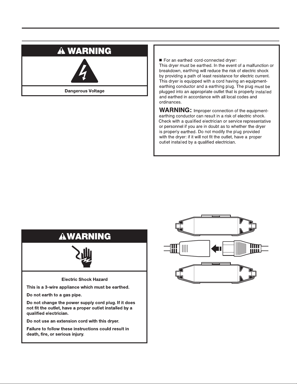
Using the universal cord included with this dryer:
The gas dryer is equipped with a universal cord with
interchangeable plugs.
1. To use the universal cord, select the plug end that ts your
electrical outlet, and plug it into the adapter on the supply
cord.
2. Secure the plug end in place on the cord by aligning the
2 cover halves over the cord adapter and clipping them
together.
If codes permit and an additional earth bond wire is used, it is
recommended that a qualied electrician determine that the
earth bond path is adequate.
11
GAS DRYER INSTALLATION REQUIREMENTS
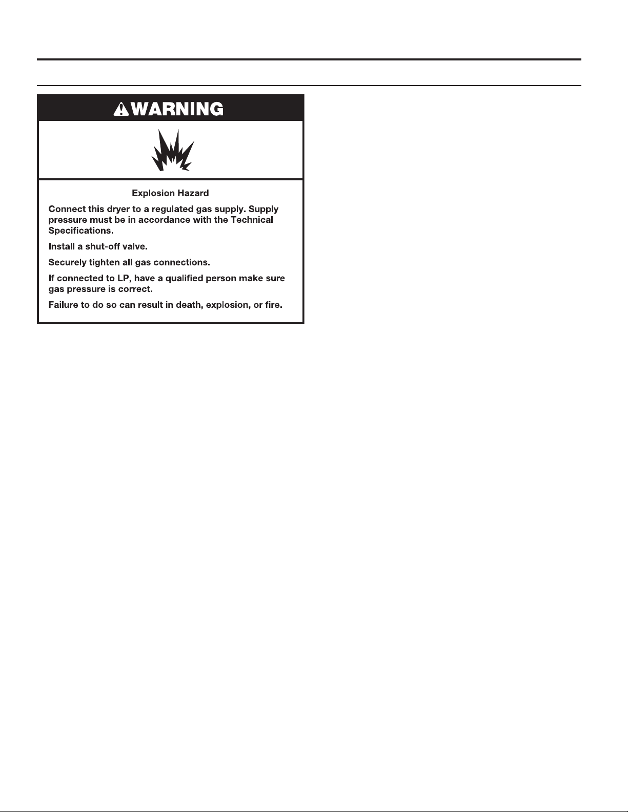
Gas Supply
Supply line requirements:
Provide a rigid gas supply line to the dryer location. It should
be minimum 12.5 mm (1/2") ID. When acceptable to the gas
supplier and local codes, 10 mm (3/8") ID rigid supply line may
be used for lengths under 6.1 m (20'). Pipe-joint compounds
resistant to the action of L.P. gas must be used.
NOTE: For installation in Australia and New Zealand, refer to
AS/NZS 5601 for pipe sizing details. All piping is to be in
accordance with AS/NZS 5601.1 – Gas Installations.
Gas connection to the dryer itself should be made by means
of a exible gas hose suitable for the appliance and gas
category in accordance with national installation regulations.
If in doubt, contact the gas supplier. It should be minimum
10 mm (3/8") ID.
A means of restraint should be used between the dryer and the
wall to avoid straining of the rigid gas supply when the dryer
is moved. An appropriate length of chain and a wall hook is
recommended.
The dryer gas inlet connection is a 10 mm (3/8") NPT thread.
An adapter is supplied for conversion to standard ISO.228-1
thread (10 mm [3/8"] BSP).
IMPORTANT: Observe all governing codes and ordinances.
In Australia and New Zealand, refer to AS/NZS 5601.1 – Gas
Installations.
Gas Supply
Before installation, check that the local gas distribution
conditions, nature of gas and pressure, and the adjustment of
the appliance are compatible. Burner information will be found
on the model/serial rating plate in the door recess of the dryer.
If this information does not agree with the type of gas available,
see your dealer.
Natural Gas:
This dryer is factory adjusted for use with NATURAL GAS (G20),
and no further adjustment should be required at installation.
L.P. Gas:
This dryer is also certied for use with L.P. (propane or butane)
gases with appropriate conversion. No attempt shall be made
to convert the appliance from the gas specied on the model/
serial rating plate for use with a different gas without consulting
the serving gas supplier.
Conversion must be done by a competent service technician.
Gas conversion kit (European Country), part number
W10233219, is available for purchase from your dealer. Gas
conversion kit (Australia), part number W10315369, is available
for purchase from your dealer. Full instructions are supplied
with the kit.
Natural Gas (France/Belgium):
This dryer is also certied for France/Belgium for use with G20/
G25 gases (20 mbar/25 mbar) with appropriate conversion. No
attempt should be made to convert this appliance from the gas
specied on the gas rating label for use with a different gas
without consulting the serving gas supplier. Gas conversion
must be done by a qualied gas service technician. Conversion
kit, part number (W10181947) is available for purchase from
your dealer. Full instructions are supplied with the kit.
Check for leaks by using an approved noncorrosive leakdetection solution. Bubbles will show a leak. Correct any leak
found. A pressure measurement tapping is provided on the gas
valve within the dryer, accessible after removal of the lower
front panel.
The dryer must be disconnected from the gas supply piping
system during any pressure testing of that system.
12
DRYER VENTING REQUIREMENTS
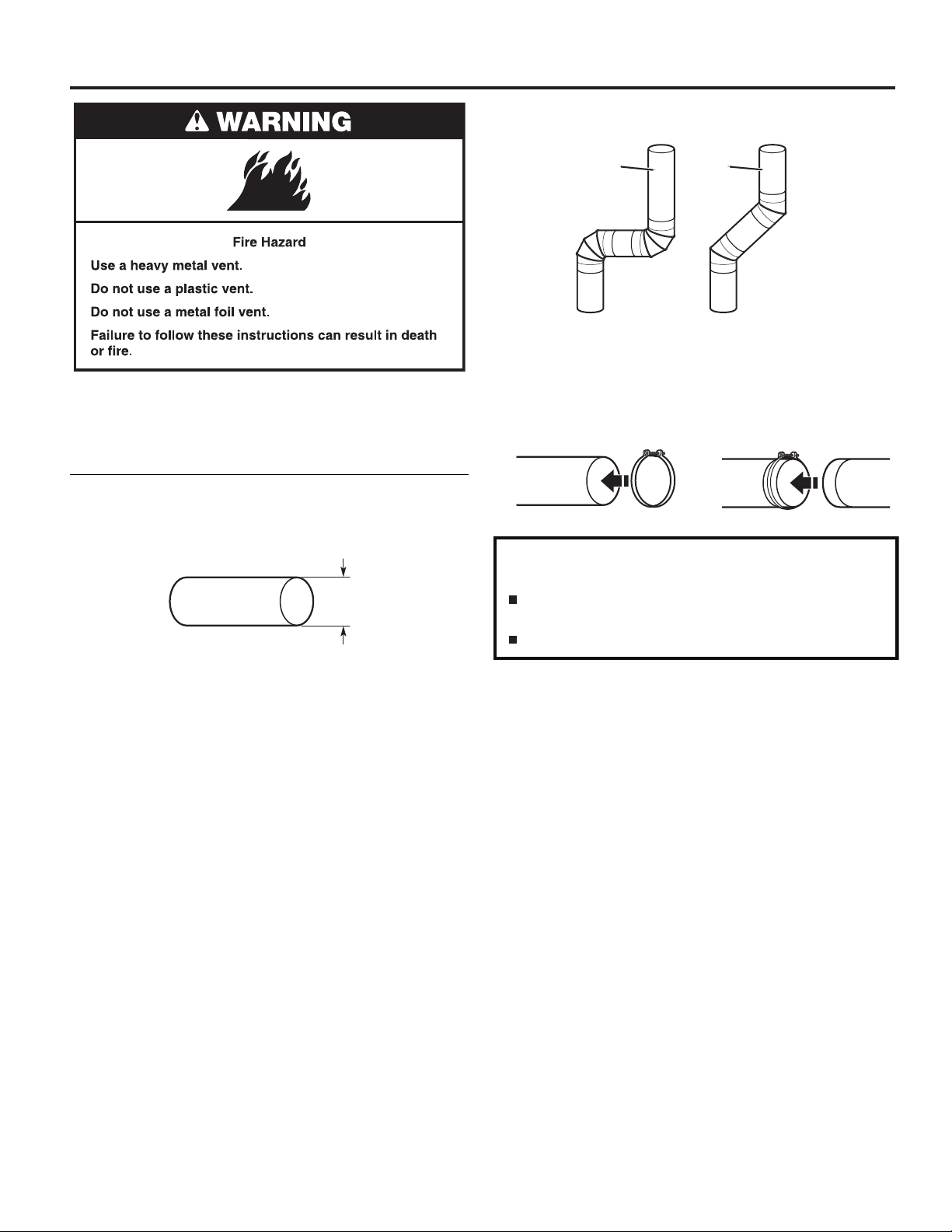
Elbows:
■ 45° elbows provide better airow than 90° elbows.
WARNING: To reduce the risk of re, this dryer MUST BE
EXHAUSTED OUTDOORS.
IMPORTANT: Observe all governing codes and ordinances.
In Australia and New Zealand, refer to AS/NZS 5601.1 – Gas
Installations.
Dryer exhaust must not be connected into any gas vent,
chimney, wall, ceiling, attic, crawlspace, or a concealed space
of a building. Only rigid or exible metal vent shall be used for
exhausting.
102 mm
(4")
102 mm (4") Heavy, Metal Exhaust Vent
Good
Better
Clamps:
■ Use clamps to seal all joints.
■ Exhaust vent must not be connected or secured with screws
or other fastening devices that extend into interior of duct
and catch lint. Do not use duct tape.
Improper venting can cause moisture and lint to collect
indoors, which may result in:
Moisture damage to woodwork, furniture, paint, wallpaper,
carpets, etc.
Housecleaning problems and health problems.
■ Only a 102 mm (4") heavy, metal exhaust vent and clamps
may be used.
■ Do not use plastic or metal foil vent.
Rigid metal vent:
■ Recommended for best drying performance and to avoid
crushing and kinking.
Flexible metal vent: (Acceptable only if accessible to clean)
■ Must be fully extended and supported in nal dryer location.
■ Remove excess to avoid sagging and kinking that may result
in reduced airow and poor performance.
■ Do not install in enclosed walls, ceilings, or oors.
■ The total length should not exceed 2.4 m (7
3
⁄4 ft.).
NOTE: If using an existing vent system, clean lint from entire
length of the system and make sure exhaust hood is not
plugged with lint. Replace plastic or metal foil vents with rigid
metal or exible metal vents. Review “Vent System Chart” and,
if necessary, modify existing vent system to achieve best drying
performance.
13
DRYER VENTING REQUIREMENTS
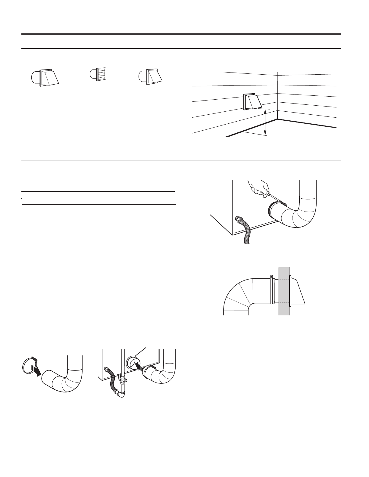
Vent Hoods
102 mm (4") Diameter Exhaust Hoods
Exhaust hood must be at least 305 mm (12") from the ground
or any object that may be in the path of the exhaust (such as
owers, rocks, bushes, or snow).
Box Hood Louvered Hood Angled Hood
Vent System Length
Maximum Vent Length/Vent Connection
Maximum length of vent system depends upon the type of vent
used, number of elbows, and type of exhaust hood.
Vent System Chart (Rigid Metal Vent)
No. of Box and Angled
90˚ Turns Louvered Hood Hood
0 39.6 m (130 ft.) 39.3 m (129 ft.)
1 38.1 m (125 ft.) 36.3 m (119 ft.)
2 35.1 m (115 ft) 33.2 m (109 ft.)
3 32.3 m (106 ft.) 30.5 m (100 ft.)
4 29.9 m (98 ft.) 28.0 m (92 ft.)
For vent systems not covered by the vent specication chart,
see your parts distributor.
Provision must be made for enough air for combustion and
ventilation. (Check governing codes and ordinances.) See
“Recessed Area and Closet Installation Instructions” in the
“Location Requirements” section.
A 102 mm (4") outlet hood is preferred. However, a 64 mm
(21⁄2") outlet exhaust hood may be used. A 64 mm (21⁄2") outlet
creates greater back pressure than other hood types. For
permanent installation, a stationary vent system is required.
Connect Vent
1. If connecting to existing vent, make sure the vent is clean.
2. Using a 102 mm (4") clamp, connect vent to exhaust outlet
in dryer.
Vent Collar
12" min.
305 mm min.
(305 mm)
(12")
3. Tighten hose clamp with Phillips screwdriver.
4. Make sure the vent is secured to exhaust hood with
a 102 mm (4") clamp.
5. Move dryer into nal position. Do not crush or kink vent.
Make sure dryer is level.
NOTE: Do not remove vent collar.
14
DRYER VENTING REQUIREMENTS
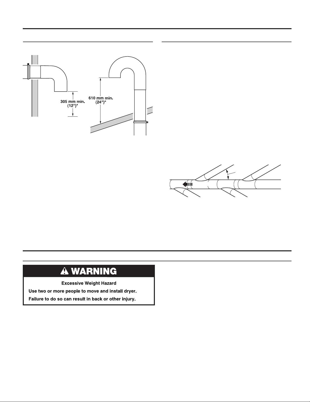
If an Exhaust Hood Cannot be Used Multiple Dryer Venting
The outside end of main vent should have a sweep elbow
directed downward.
* Minimum clearance above any
accumulation of snow, ice, or
debris such as leaves
If main vent travels vertically through the roof, rather than
through wall, install a 180° sweep elbow on end of vent at least
610 mm (2 ft.) above surface of roof.
The opening in wall or roof shall have a diameter 13 mm (1⁄2")
larger than vent diameter. Vent should be centered in opening.
Do not install screening over end of vent for best performance.
A main vent can be used for venting a group of dryers. The
main vent should be sized to remove 5663 l/min. (200 CFM) of
air per dryer. Large-capacity lint screens of proper design may
be used in main vent if checked and cleaned frequently. The
room where the dryers are located should have make-up air
equal to or greater than CFM of all the dryers in the room.
Back-draft dampers are available from your distributor and
should be installed in the vent of each dryer to keep exhausted
air from returning into dryers and to keep exhaust in balance
within main vent. Unobstructed return air openings are required.
Although usually each single-load dryer should have an
unobstructed outdoor air opening of 154 cm2 (24 in.2) (based
on 6.5 cm2 [1 in.2] per 252 kcal [1,000 Btu]), common make-up
air openings are also acceptable. Set up common openings so
the make-up air is distributed equally to all of the dryers. Keep
in mind that the coverage area must be increased by 33% to
account for the use of registers or louvers over the openings.
Also, make-up air openings should not be installed near the
location where exhaust vents exit the building.
Each vent should enter the main vent at an angle pointing in
the direction of the airow. Vents entering from the opposite
side should be staggered to reduce the exhausted air from
interfering with the other vents.
Air Flow
air ow
30˚ max.
GAS SUPPLY CONNECTION (on some models)
Make Gas Connection
1. Remove red cap from gas pipe on back of dryer.
2. Connect gas supply to dryer. If the exible gas hose has
10 mm (3/8") BSP thread, use the supplied conversion
thread adapter. Use pipe-joint compound resistant to the
action of L.P. gas for gas connections.
If necessary for service, open the toe panel. Use a putty
knife to press on the 2 toe panel locks located at the top
of the toe panel. Pull downward on the toe panel to open.
Toe panel is hinged at the bottom.
3. Open the shut-off valve in the gas supply line and make sure
the dryer has its own gas supply opened.
4. Test all connections by brushing on an approved
noncorrosive leak-detection solution. Bubbles will show
a leak. Correct any leaks found.
The maximum angle of each vent entering the main vent should
be no more than 30°.
Keep air openings free of dry cleaning uid fumes. Fumes
create acids which, when drawn through the dryer heating
units, can damage dryers and items being dried.
A clean-out cover should be located on the main vent for
periodic cleaning of the vent system.
15
INSTALLING LEVELING LEGS
2. Screw in leveling legs
Examine leveling legs and nd diamond
marking. Screw legs into leg holes by
hand. Use an adjustable wrench or
25 mm (1") hex-head socket wrench
to nish turning legs until diamond
marking is no longer visible. Then t
a covered foot boot over each leg foot.
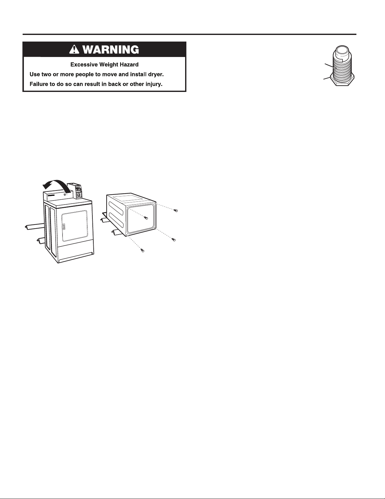
1. Prepare dryer for leveling legs
NOTE: Slide dryer onto cardboard or hardboard before moving
to avoid damaging oor covering.
Using two or more people, move dryer to desired installation
location.
Take tape off front corners of dryer. Open dryer and remove
the literature and parts packages. Wipe drum interior with a
damp cloth to remove any dust.
Take two cardboard corners from the dryer carton and place
them on the oor in back of the dryer. Firmly grasp the body of
the dryer and gently lay it on its back on the cardboard corners.
To protect the oor, use a large piece of cardboard from the
dryer carton. Stand dryer up on the cardboard. Slide the dryer
until it is close to its nal location. Leave enough room for
electrical connection and to connect the exhaust vent.
Diamond
Marking
Foot
16
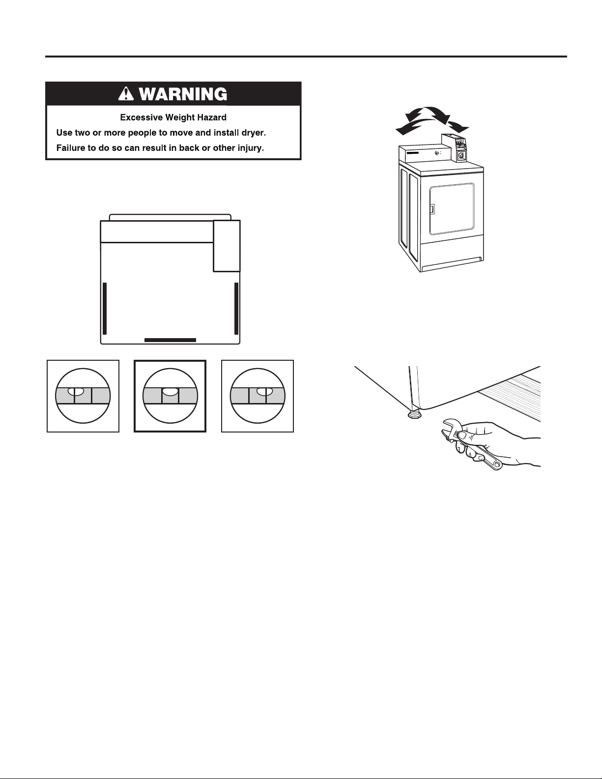
LEVELING
Leveling your dryer properly reduces excess noise and vibration.
1. Remove cardboard from beneath dryer. Place a level on top
edges of dryer, checking each side and front. If not level,
tip dryer and adjust legs up or down as shown in Step 3,
repeating as necessary.
2. Grip dryer from top and rock back and forth, making sure all
four legs are rmly on oor. Repeat, rocking dryer from side
to side. If dryer rocks, go to Step 3 and adjust leveling legs.
3. If dryer is not level, use a 25 mm (1") open-end or adjustable
wrench to turn the leveling leg counterclockwise to lower the
dryer or clockwise to raise the dryer. Recheck levelness of
dryer and that all four legs are rmly in contact with the oor.
Repeat as needed.
HELPFUL TIP: You may want to prop up front of dryer about
102 mm (4") with a wood block or similar object that will
support weight of dryer.
Not Level LEVEL Not Level
17
COMPLETE INSTALLATION
1. Check the electrical requirements. Be sure that you have
the correct electrical supply and the recommended earthing
method. See “Electrical Requirements.”
2. Check that all parts are now installed. If there is an extra part,
go back through the steps.
3. Check that you have all of your tools.
4. Dispose of/recycle all packaging materials.
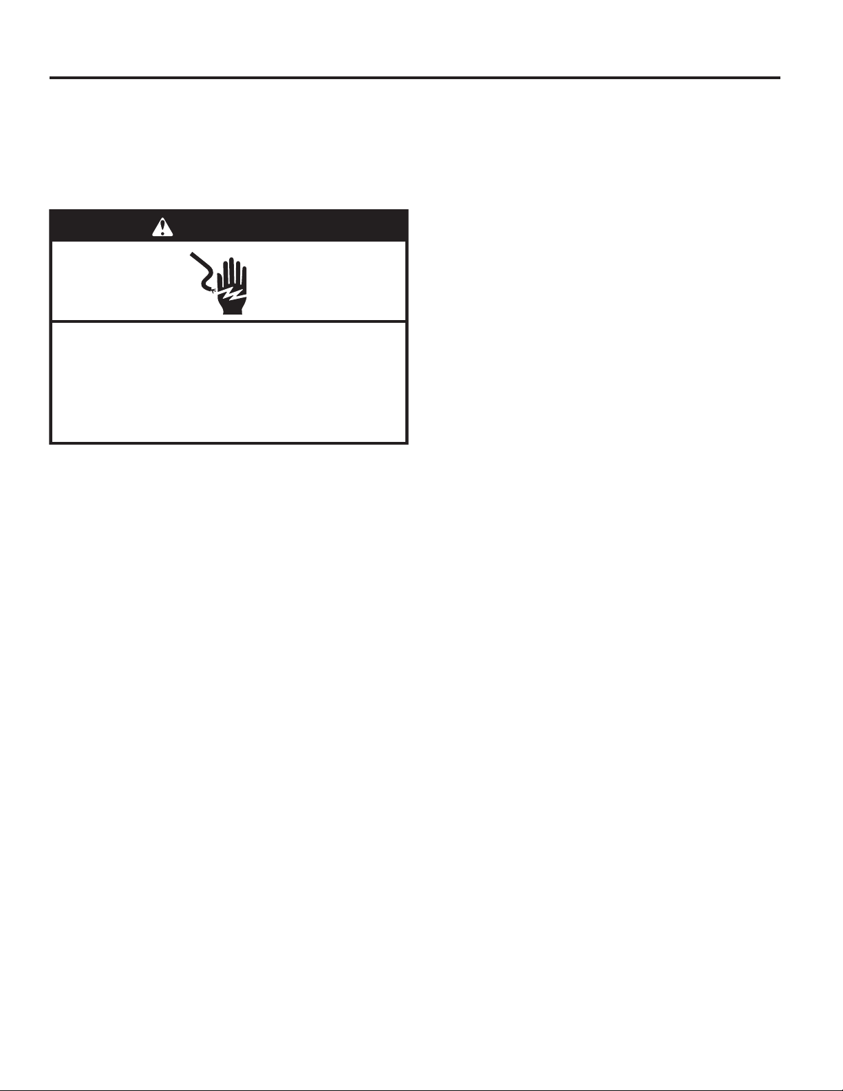
WARNING
Electric Shock Hazard
This dryer must be earthed.
Securely tighten all electrical connections.
Failure to do so can result in death, fire, or
electric shock.
5. Plug into an earthed outlet, or connect power.
6. Check dryer operation (some accumulated time may be
on the timer due to factory testing). Close dryer door. Insert
coins in slide and press slide in slowly. (Operating time will
accumulate per number of coins and type of timing cam
used.) Push START button. Using a full heat cycle (not the
air cycle), let the dryer run for at least ve minutes. Dryer will
stop when time is used up.
NOTE: Dryer door must be closed for dryer to operate.
When door is open, dryer stops, but timer continues to run.
To restart dryer, close door and push START button.
7. Gas models only: Open the dryer door. Check that the
inside of the dryer is warm. If the burner does not ignite and
you can feel no heat inside the dryer, shut off dryer for ve
minutes. Check that all supply valve controls are in “ON”
position and that the electrical cord is plugged in. Repeat
ve-minute test.
8. If drying time is too long, make sure that the lint screen is
clean and that there are no obstructions to airow in the
dryer vent system.
9. Restart the dryer and allow it to complete a full heat cycle
(not air cycle) to make sure it is working properly.
18
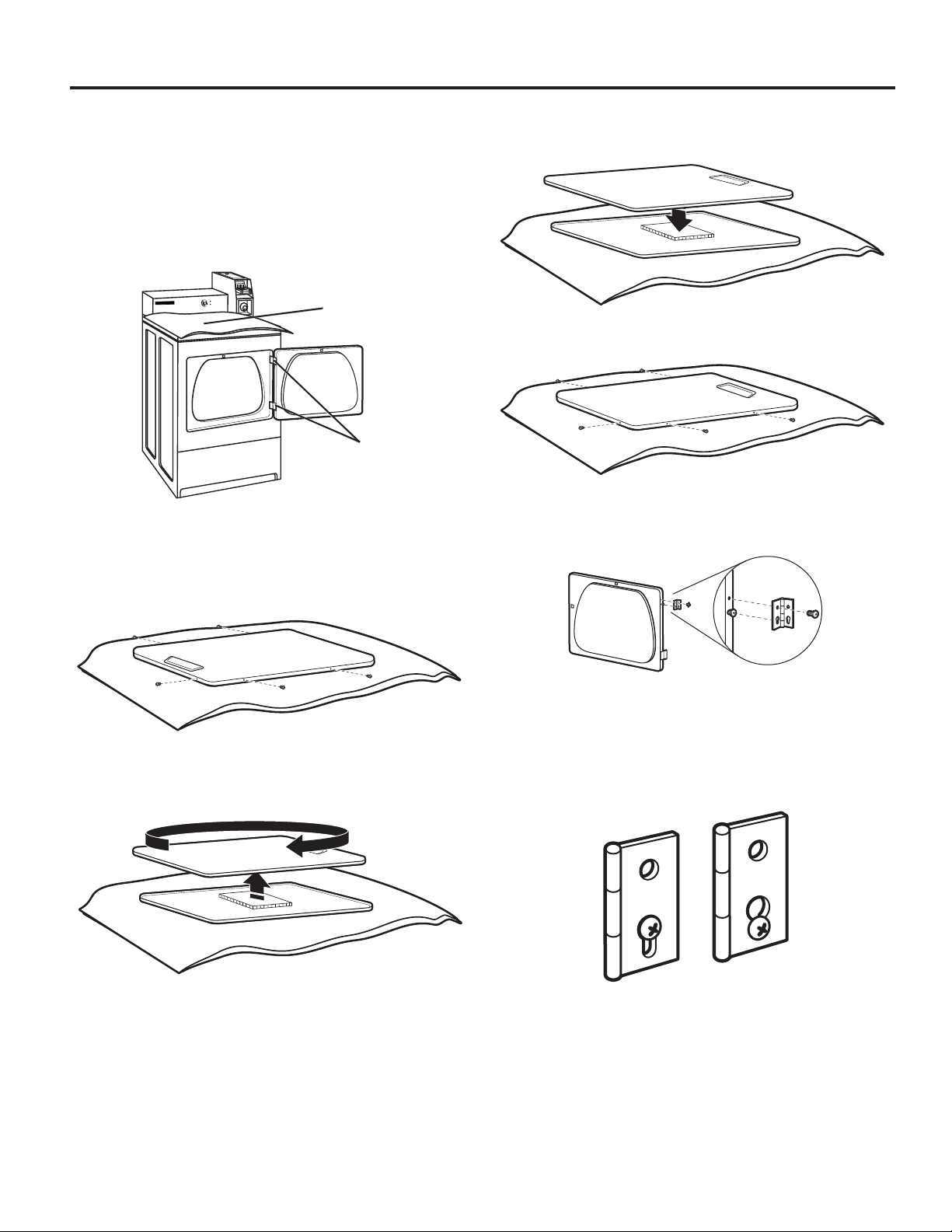
REVERSING DRYER DOOR SWING (OPTIONAL)
You can change your door swing from a right-side opening
to left-side opening, if desired.
Remove the Door Assembly
1. Place a towel or soft cloth on top of dryer or work space to
avoid scratching of the surface.
2. Open dryer door. Remove bottom screws from cabinet side
of hinges. Loosen (do not remove) top screws from cabinet
side of hinges.
Towel
Hinges
3. Lift door until top screws in cabinet are in large part of hinge
slot. Pull forward off screws. Set door (handle side up) on
top of dryer. Remove top screws from cabinet.
4. Remove screws attaching hinges to door.
5. Remove screws at top, bottom, and side of door (5 screws).
7. Be certain to keep cardboard spacer centered between
doors. Reattach outer door panel to inner door panel so
handle is on the side where hinges were just removed.
8. Reattach screws at top, bottom, and side of door (5 screws).
9. Attach door hinges to dryer door so that larger hole is at the
bottom of the hinge and the hinge pin is toward the door
front.
6. Holding door over towel on dryer, grasp sides of outer door
and gently lift to separate it from inner door. Do not use a
putty knife to pry apart. Do not pull on door seal or plastic
door catch.
10. Remove the 4 screws that attach 2 plugs on the left side.
Attach plugs to right side using the same 4 screws.
11. Insert screws into bottom holes on left side of cabinet.
Tighten screws halfway. Position door so large end of door
hinge slot is over screws. Slide door up so screws are in
bottom of slots. Tighten screws. Insert and tighten top
screws in hinges.
12. Close door and check that door strike aligns with door
catch. If needed, slide door catch left or right within slot to
adjust alignment.
19
MAINTENANCE INSTRUCTIONS
GPO, Schorndorf
GPO, Schorndorf
■ Clean lint screen before and after each cycle.
■ Removing accumulated lint:
From inside the dryer cabinet:
Lint should be removed every 2 years or more often,
depending on dryer usage. Cleaning should be done by
a qualied person.
From the exhaust vent:
Lint should be removed every 2 years, or more often,
depending on dryer usage.
■ Keep area around dryer clear and free from combustible
materials, petrol, and other ammable vapors and liquids.
■ Keep dryer area clear and free from items that would
obstruct the ow of combustion and ventilation air.
IF YOU NEED ASSISTANCE
If you need help, contact the dealer from whom you purchased
the appliance, or a Whirlpool designated service company.
When calling, please know the purchase date and the complete
model and serial number of your appliance. This information will
help us to better respond to your request.
If dryer does not operate, check the following:
■ Electrical supply is connected.
■ Circuit breaker is not tripped or house fuse is not blown.
■ Door is closed. Listen closely to hear the door switch
activate.
■ Controls are set in a running or “on” position.
■ START button has been pushed rmly.
■ For gas dryers, check that gas supply shut-off valves are set
in open position.
EU - DECLARATION OF CONFORMITY
CE - DECLARATION DE CONFORMITE
WE (nous):
BAUKNECHT HAUSGERÄTE GmbH, D-73614 Schorndorf
representing (représentant):
declare under our sole responsibility that the product
déclarons sous notre propre respon sabilité que le produit
dryer Maytag MDE18CS
(séche linge):
Whirlpool XCEM2763
to which this declaration relates is in conformity with the following standard(s) or other
normative document(s)
auquel se référe cette déclaration est con forme aux normes suivantes ou autres documents normatifs
EN 60335-1: 2002+A1+A2+A11+A12+A13+A14+A15
EN 60335-2-11: 2010
EN 62233: 2008+Ber.1: 2008
EN ISO 10472-1: 2008
EN ISO 10472-4: 2008
EN ISO 14121-1: 2007
EN 55014-1: 2006+A1:2009+A2:2011 (Test method > 30 MHz: Disturbance pow er)
EN 55014-2: 1997+A1:2001+A2:2008
EN 61000-3-12: 2005
EN 61000-3-11: 2000
following the provisions of Directive(s
suivant les previsions des Directives:
2006/42/EC Machinery Directive
2006/95/EC Low Voltage Directive
2004/108/EC Electromagnetic Compatibility Directive
2011/65/EU RoHS Directive
Schorndorf, 10.10.2013
Place and date:
lieu et date
Name and signature of aurthorised perso n
Nom et signature de la personne autorisée
WHIRLPOOL EUROPE S.r.l I-21025 COMERIO
Maytag MDE18MN
(CEE Directive Machine)
(CEE Directive RoHs)
Year of CE Marking (Année d’apposition du marquage CE): 2013
):
(CEE Directive Basse Tension)
Micael Zirondi Karl-Dieter Kli ngenstein
Director PDC FC EMEA Product Approval
(CEE Directive Compatibilité Electro-magnétique)
EU - DECLARATION OF CONFORMITY
CE - DECLARATION DE CONFORMITE
WE (nous):
BAUKNECHT HAUSGERÄTE GmbH, D-73614 Schorndorf
representing (représentant):
declare under our sole responsibility that the product
déclarons sous notre propre respon sabilité que le produit
dryer Maytag MDG18CS
(séche linge):
Whirlpool XCGM2763
to which this declaration relates is in conformity with the following standard(s) or other
normative document(s)
auquel se référe cette déclaration est con forme aux normes suivantes ou autres documents normatifs
EN 60335-1: 2012
EN 60335-102: 2006+A1:2010 incl. Corr 1&2
EN 62233: 2008+Ber.1: 2008
EN ISO 10472-1: 2008
EN ISO 10472-4: 2008
EN ISO 14121-1: 2007
EN 55014-1: 2006+A1:2009+A2:2011 (Test method > 30 MHz: Disturbance pow er)
EN 55014-2: 1997+A1:2001+A2:2008
EN 61000-3-2:2006+A1:2009+A2:2009
EN 61000-3-3:2008
following the provisions of Directive(s
suivant les previsions des Directives:
2006/42/EC Machinery Directive
2006/95/EC Low Voltage Directive
2009/142/EC Gas Appliances Directive
2004/108/EC Electromagnetic Compatibility Directive
2011/65/EU RoHS Directive
Schorndorf, 10.10.2013
Place and date:
lieu et date
Name and signature of aurthorised perso n
Nom et signature de la personne autorisée
WHIRLPOOL EUROPE S.r.l I-21025 COMERIO
Maytag MDG18MN
(CEE Directive Machine)
(CEE Directive RoHs)
Year of CE Marking (Année d’apposition du marquage CE): 2013
):
(CEE Directive Basse Tension)
(CEE Directive relative aux appareils à gaz)
(CEE Directive Compatibilité Electro-magnétique)
Micael Zirondi Karl-Dieter Kli ngenstein
Director PDC FC EMEA Product Approval
20
TECHNICAL SPECIFICATIONS – GAS DRYER
220–240V~50Hz 1ph 3A max. IP24 Clothes capacity: 9.0 kg max. Sound pressure level, Lpa: 58 dBA (uncertainty, Kpa: +/-10 dBA) Total mass: 68 kg max.
Factory set for NATURAL GAS: Injector size: 2.2 mm Heat input gross: 5.9 kW
Country: CH, CZ, CY, ES, GB, GR,
HR, IE, IT, PT, SI, SK, TR
European Gas Category:
Gas Flow Rate: .562703 m3/hr 0.562703 m3/hr
Supply Pressure (G20): 20 mbar 20 mbar
Factory Adjusted Pressure: 7.4 mbar 7.4 mbar
With LP Gas Conversion Kit: Injector size: 1.25 mm Heat input gross: 6.4 kW
European Country: CH, CZ, CY, ES, GB, GR, HR,
European Gas Category:
Butane Supply Pressure (G30): 28–30 mbar 30 mbar
Adjusted Pressure: N/A N/A
Propane Supply Pressure (G31): 37 mbar 30 mbar
Adjusted Pressure: N/A N/A
With France/Belgium NATURAL GAS conversion kit: Injector size 1.65 mm Heat input gross: 5.9 kW
European Country: FR, BE
European Gas Category:
Supply Pressure (G20): 20 mbar
Supply Pressure (G25): 25 mbar
Adjusted Pressure: N/A
II
2H3+
IE, IT, PT, SI, SK, TR
II
2H3+
I
2E+
CY, CZ, DK, EE, FI, GR, HU,
IT, NO, RO, SE, SK, TR
II
2H3B/P
CY, CZ, DK, EE, FI, GR, HU,
IT, NO, RO, SE, SK, TR
II
2H3B/P
Factory set for Australia/New Zealand NATURAL GAS: Injector size: 2.2 mm Heat input gross: 5.9 kW
Country: AS, NZS
Supply Pressure (G20) minimum 1.13 kPa
Adjusted Pressure (Test Point Pressure): 0.74 kPa
Nominal Hourly Gas Consumption 21.1 MJ/h
With Australia LG Gas Conversion Kit: Injector Size: 1.40 mm Heat input gross: 6.54 kW
Country: AS, NZS
Propane Supply Pressure: 2.75 kPa
Adjusted Pressure: 2.75 kPa
Nominal Hourly Gas Consumption: 23 MJ/h
Factory set for NATURAL GAS: Injector size: 2.2 mm Heat input gross: 5.0 kW
Country: NL
European Gas Category:
Gas Flow Rate: 0.562703 m3/hr
Supply Pressure (G25): 25 mbar
Factory Adjusted Pressure (G25) : 7.4 mbar
Supply Pressure (G30/G31): 30 mbar
Factory Adjusted Pressure (G30/G31): N/A
NOTE: Conversion kit: From Natural Gas to LP Gas - Europe: Whirlpool Part No. W10233219.
Conversion kit: From Natural Gas to LP Gas - Australia: Whirlpool Part No. W10315369.
Conversion kit: From Natural Gas to Natural Gas - France/Belgium: Whirlpool Part No. W10181947.
Manufacturer: Whirlpool Corporation, Benton Harbor, Michigan 49022, U.S.A.
Manufacturing Site: Whirlpool Corporation, 1300 Marion-Agosta Rd., Marion, OH, 43302, U.S.A.
EU Representatives: Maytag UK Ltd., 2 St. Annes Blvd., Redhill, RH1 1AX, UK & Bauknecht Hausgeräte GmbH, D-73614 Schorndorf, Germany
II
2L3B/P
21
WHIRLPOOL COMMERCIAL LAUNDRY® WARRANTY
THREE YEAR LIMITED WARRANTY (PARTS ONLY – LABOR NOT INCLUDED)
For three years from the original date of purchase, when this commercial appliance is installed, maintained and operated according
to instructions attached to or furnished with the product, Whirlpool Corporation (thereafter “Whirlpool”) will pay for factory specied
replacement parts to correct defects in materials or workmanship that existed when this commercial appliance was purchased. This
limited warranty does not include labor.
YOUR SOLE AND EXCLUSIVE REMEDY UNDER THIS LIMITED WARRANTY SHALL BE PRODUCT REPAIR AS PROVIDED HEREIN.
Whirlpool recommends that you use an “in network” service provider to diagnose and repair your Commercial Laundry product.
Whirlpool will not be responsible under this warranty to provide additional replacement parts as a result of incorrect diagnosis or
repair by an “out of network” service company. This limited warranty is valid in the United States or Canada and applies only when
the major appliance is used in the country in which it was purchased. This limited warranty is effective from the date of the original
consumer purchase. Proof of original purchase date is required to obtain service under this limited warranty.
ITEMS EXCLUDED FROM WARRANTY
This limited warranty does not cover:
1. All other costs including labor, transportation, shipping, or custom duties for covered parts.
2. Factory specied replacement parts if this commercial appliance is used for other than normal, commercial use or when it is
used in a manner that is inconsistent to published user or operator instructions and/or installation instructions.
3. Service calls to correct the installation of your commercial appliance, to instruct you on how to use your commercial appliance,
to replace or repair fuses, or to correct external wiring or plumbing.
4. Service calls to repair or replace appliance light bulbs, air lters, or water lters. Consumable parts are excluded from warranty
coverage.
5. Damage resulting from improper handling of product during delivery, theft, accident, alteration, misuse, abuse, re, ood, acts
of God, improper installation, installation not in accordance with local electrical or plumbing codes, or use of products not
approved by Whirlpool.
6. Pick up and Delivery. This commercial appliance is designed to be repaired on location.
7. Repairs to parts or systems resulting from unauthorized modications made to the commercial appliance.
8. The removal and reinstallation of your commercial appliance if it is installed in an inaccessible location or is not installed in
accordance with published installation instructions.
9. Damage resulting from exposure to chemicals.
10. Changes to the building, room, or location needed in order to make the commercial appliance operate correctly.
11. Factory specied replacement parts on commercial appliances with original model/serial numbers that have been removed,
altered, or cannot be easily determined.
12. Discoloration, rust, or oxidation of stainless steel surfaces.
13. Factory specied replacement parts as a result of incorrect diagnosis or repair by an “out of network” service company.
The cost of repair or replacement under these excluded circumstances shall be borne by the customer.
DISCLAIMER OF IMPLIED WARRANTIES
IMPLIED WARRANTIES, INCLUDING ANY IMPLIED WARRANTY OF MERCHANTABILITY OR IMPLIED WARRANTY OF FITNESS
FOR A PARTICULAR PURPOSE, ARE LIMITED TO THREE YEARS OR THE SHORTEST PERIOD ALLOWED BY LAW. Some states
and provinces do not allow limitations on the duration of implied warranties of merchantability or tness, so this limitation may
not apply to you. This warranty gives you specic legal rights, and you also may have other rights that vary from state to state
or province to province.
DISCLAIMER OF REPRESENTATIONS OUTSIDE OF WARRANTY
Whirlpool makes no representations about the quality, durability, or need for service or repair of this major appliance other than
the representations contained in this Warranty. If you want a longer or more comprehensive warranty than the limited warranty that
comes with this major appliance, you should ask Whirlpool or your retailer about buying an extended warranty.
LIMITATION OF REMEDIES; EXCLUSION OF INCIDENTAL AND CONSEQUENTIAL DAMAGES
YOUR SOLE AND EXCLUSIVE REMEDY UNDER THIS LIMITED WARRANTY SHALL BE PRODUCT REPAIR AS PROVIDED HEREIN.
WHIRLPOOL SHALL NOT BE LIABLE FOR INCIDENTAL OR CONSEQUENTIAL DAMAGES. Some states and provinces do not allow
the exclusion or limitation of incidental or consequential damages, so these limitations and exclusions may not apply to you. This
warranty gives you specic legal rights, and you also may have other rights that vary from state to state or province to province.
If you need service, please contact your authorized Whirlpool Commercial Laundry® distributor. Outside the 50 United States
and Canada, this warranty does not apply. Contact your authorized Whirlpool dealer to determine if another warranty applies.
To locate your authorized Whirlpool Commercial Laundry® distributor, call 1-800-662-3587, or for web inquiries, visit
www.WhirlpoolCommercialLaundry.com.
For written correspondence:
Whirlpool Commercial Laundry® Service Department
2000 N M 63
Benton Harbor, Michigan 49022-2632 USA
11/13
22
SECURITE DU SECHE-LINGE
■ On recommande que le propriétaire place les instructions à l’usage du client en un lieu bien visible, au cas où le client percevrait
une odeur de gaz. Ces renseignements doivent être obtenus auprès de votre fournisseur en gaz.
■ Placer l’avertissement qui suit à un endroit bien visible.
POUR VOTRE SECURITE
1. NE PAS UTILISER OU REMISER D’ESSENCE OU AUTRES MATÉRIAUX INFLAMMABLES DANS CET APPAREIL MÉNAGER
O U À PROXIMITÉ DE CELUI-CI.
2. NE PAS VAPORISER D’AÉROSOLS À PROXIMITÉ DE CET APPAREIL MÉNAGER LORSQU’IL EST EN FONCTIONNEMENT.
3. NE PAS MODIFIER CET APPAREIL MÉNAGER.
23
SECURITE DU SECHE-LINGE
IMPORTANT : Pour mettre l’ancien sèche-linge au rebut ou pour la remiser, enlever la porte.
24

SECURITE DU SECHE-LINGE
IMPORTANTES INSTRUCTIONS DE SÉCURITÉ
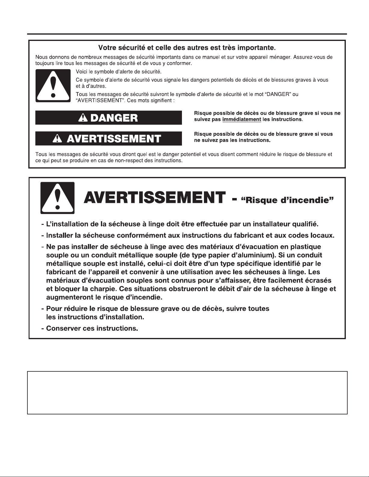
AVERTISSEMENT : Pour réduire les risques d’incendie, de choc électrique ou de blessures lors de l’utilisation
du sèche-linge, suivre les précautions fondamentales dont les suivantes :
■ Lire toutes les instructions avant d’utiliser le sèche-linge.
■ Ce sèche-linge est conçue uniquement pour le séchage
de vêtements et de textiles ayant été nettoyés à l’eau.
Ne pas l’utiliser à toute autre n.
■ AVERTISSEMENT: Si l’on détecte une odeur de gaz,
ne pas utiliser le sèche-linge ou tout autre équipement
électrique situé à proximité. Avertir les autres personnes
qu’elles doivent évacuer cette zone. Contacter
le propriétaire du sèche-linge immédiatement.
■ Ne pas placer des articles exposés aux huiles de cuisson
dans votre sèche-linge. Les articles contaminés par des
huiles de cuisson peuvent contribuer à une réaction
chimique qui pourrait causer à la charge de s’enammer.
■ Si on doit absolument placer des tissus qui contiennent
de l’huile végétale ou de cuisson ou qui ont été
contaminés par des produits de soin des cheveux dans
un sèche-linge, faut d’abord les laver dans de l’eau
chaude avec un supplément de détergent; ceci réduira
le danger, sans toutefois l’éliminer.
■ Ne pas faire sécher des articles qui ont été nettoyés ou
lavés avec de l’essence ou imbibés d’essence, solvants
de nettoyage à sec, ou autres substances inammables
ou explosives; ces substances peuvent émettre des
vapeurs susceptibles de s’enammer ou d’exploser.
■ Les articles qui ont été souillés avec des substances
comme de l’acétone, de l’alcool, du pétrole, du kérosène,
des détachants, de la térébenthine, des cires et des
décapants pour cire doivent être lavés à l’eau chaude
avec un supplément de détergent avant d’être séchés
dans le sèche-linge.
■ Ne pas faire sécher dans le sèche-linge des articles
nonlavés.
■ Ne pas utiliser ce sèche-linge si l’on a utilisé des
produits chimiques industriels pour le nettoyage. La
présence éventuelle de quantités résiduelles de produits
chimiques corrosifs ou décomposés dans la charge
peut endommager le sèche-linge et produire des fumées
toxiques.
■ Ne pas laisser des enfants jouer sur ou à l’intérieur
du sèche-linge. Bien surveiller les enfants lorsque
le sèche-linge est utilisé à proximité d’enfants.
■ Ce sèche-linge n’est pas conçu pour une utilisation
par des personnes (notamment des enfants) aux
capacités physiques, sensorielles ou mentales réduites,
ou manquant d’expérience ou de connaissances, à
moins qu’elles soient supervisées par une personne
responsable ou aient reçu des instructions adaptées
pour utiliser le sèche-linge en toute sécurité.
■ Avant de retirer le sèche-linge pour un dépannage
ou pour le jeter, ôter la porte du compartiment
du sèche-linge.
■ Ne pas tenter d’atteindre un article à l’intérieur de la cuve
du sèche-linge lorsque le tambour est en mouvement.
■ Ne pas ouvrir la porte lorsque le sèche-linge est
en marche. Il s’arrêtera.
■ Lors du chargement ou du rechargement du sèche-linge,
éviter de toucher les parties métalliques chaudes du
tambour (risque de brûlure).
■ Si la rotation du tambour est entravée par des tissus
coincés, déconnecter le sèche-linge de l’alimentation
électrique avant de retirer la source d’obstruction avec
précaution.
■ Ne pas utiliser le sèche-linge s’il ne chauffe pas, s’il
semble défectueux ou endommagé. Contacter le
propriétaire.
■ Ne pas installer ou remiser ce sèche-linge à un endroit
où il serait exposée aux intempéries.
■ Ne pas modier les organes de commande.
■ Nettoyer le ltre à charpie avant et après chaque charge.
■ Ne pas utiliser ce sèche-linge si le ltre à peluches
n’est pas installé.
■ Ne pas réparer ou remplacer un composant quelconque
du sèche-linge, ni entreprendre une opération de
service, si ce n’est spéciquement recommandé
dans ce manuel ou dans un manuel d’instructions
de réparations destiné à l’utilisateur; il est alors essentiel
que la personne concernée comprenne ces instructions
et soit compétente pour les exécuter.
■ Ne pas utiliser un produit assouplissant de tissu ou des
produits pour éliminer la statique à moins qu’ils ne soient
recommandés par le fabricant du produit assouplissant
de tissu ou du produit.
■ Ne pas utiliser la chaleur pour faire sécher des articles
fabriqués avec du caoutchouc mousse ou de matériaux
semblables.
■ La dernière partie d’un programme de séchage
par culbutage a lieu sans chaleur (programme de
refroidissement) pour faire en sorte que les articles
soient laissés à une température qui garantit que les
articles ne seront pas endommagés.
■ AVERTISSEMENT: Ne jamais arrêter le séchage par
culbutage avant la n du programme de séchage sauf
si tous les articles sont retirés rapidement et répartis pour
une dissipation de la chaleur (permet d’éviter le risque de
combustion spontanée).
■ En cas de coupure de l’alimentation électrique, retirer
rapidement la charge et l’étaler pour éviter tout risque
de combustion spontanée.
■ Ne pas laisser la charpie, la poussière, ou la saleté
s’accumuler autour du système d’évacuation ou autour
de l’appareil.
■ Les ouvertures de ventilation pour l’arrivée d’air frais
dans la pièce et dans le sèche-linge ne doivent pas être
obstruées ou scellées.
■ Commande d’arrêt d’urgence : En cas d’urgence, la prise
d’alimentation secteur doit être retirée.
■ Un nettoyage périodique de l’intérieur du sèche-linge
et du conduit d’évacuation doit être effectué par une
personne qualiée.
■ Voir la section “Spécications électriques” pour les
instructions de mise à la terre.
CONSERVEZ CES INSTRUCTIONS
25
ELIMINATION DU SECHE-LINGE
NOMENCLATURE DES MODÈLES :
CGM – Whilrpool gaz CS – Module de commande électronique avec chute de pièce activé
CEM – Whirlpool électrique MN – Module de commande électronique sans paiement
2763 – Numéro de type du modèle
26
 Loading...