

Whirlpool WTW8100BW, MVWB700BW, MVWB725BW, WTW8000BW Quick Start Manual
Washer Installation Instructions
Instructions d’installation de la laveuse
Para una versión de estas instrucciones en español, visite www.whirlpool.com
Table of Contents
WASHER SAFETY .............................................................1
INSTALLATION REQUIREMENTS ....................................2
Tools and Parts .................................................................... 2
Location Requirements ...................................................... 3
Drain System ....................................................................... 4
Electrical Requirements ..................................................... 4
INSTALLATION INSTRUCTIONS ......................................5
Remove Shipping Materials ............................................... 5
Connect Drain Hose ............................................................ 5
Connect Inlet Hoses ............................................................ 6
Level Washer ....................................................................... 7
COMPLETE INSTALLATION CHECKLIST .......................9
INSTALLATION NOTES
Date of purchase: _________________________________
Date of installation: _______________________________
Installer: ________________________________________
Model number: ___________________________________
Serial number: ___________________________________
Table des matières
SÉCURITÉ DE LA LAVEUSE ...........................................10
EXIGENCES D’INSTALLATION .......................................11
Outillage et pièces ............................................................. 11
Exigences d’emplacement ................................................ 12
Système de vidange .......................................................... 13
Spécications électriques ................................................. 13
INSTRUCTIONS D’INSTALLATION .................................14
Retrait de la base d’expedition et
de l’emballage en anneau .................................................. 14
Raccordement du tuyau d’evacuation ............................. 14
Raccordement des tuyaux de vidange ............................. 15
Mise à niveau de la laveuse ............................................... 17
LISTE DE VÉRIFICATION
POUR INSTALLATION TERMINÉE ..................................19
NOTES CONCERNANT L’INSTALLATION
Date d’achat : _____________________________________
Date d’installation : ________________________________
Installateur : ______________________________________
Numéro du modèle : ________________________________
Numéro de série : __________________________________
W10196566C
W10196567C-SP
WASHER SAFETY
INSTALLATION REQUIREMENTS
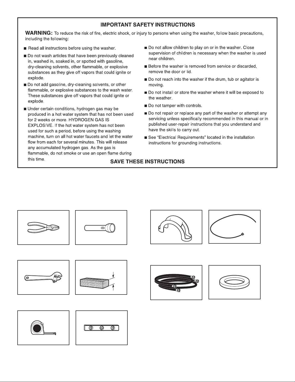
TOOLS AND PARTS
Gather the required tools and parts before starting installation.
Tools needed:
Pliers that open to 19/16"
(39.5 mm)
Adjustable or open end
wrench 9/16" (14 mm)
Flashlight (optional)
4" min
(102 mm)
Wood block
Parts supplied (located in the washer basket):
Drain hose form
Cable Tie
Parts needed (Not supplied with washer):
Water inlet hoses (2)
Flat inlet hose washers (4)
Tape measure or ruler Level
2
To order, please refer to the phone number or website on the
14" max.
(356 mm)
back page of your “Use and Care Guide.”
■ 8212656RP 10 ft. (3.0 m) Inlet hose, Black EPDM (2 pack)
■ 8212641RP 5 ft. (1.5 m) Inlet hose, Black EPDM (2 pack)
■ 8212646RP 4 ft. (1.2 m) Inlet hose, Black EPDM (2 pack)
■ 8212545RP 5 ft. (1.5 m) Inlet hose, Red and Blue EPDM
(2 pack)
■ 8212487RP 5 ft. (1.5 m) Nylon braided inlet hose (2 pack)
■ 8212638RP 6 ft. (1.8 m) Nylon braided inlet hose, space
saving 90° elbow, hypro-blue steel couplings
(2 pack)
■ 8212637RP 6 ft. (1.8 m) Inlet hose, Black EPDM, space
saving 90° elbow, hypro-blue steel couplings
(2 pack)
Alternate parts (Not supplied with washer):
Your installation may require additional parts. To order, please
refer to the phone number or website on the back page of your
“Use and Care Guide.”
You will need:
■ A water heater set to deliver 120°F (49°C) water to the washer.
■ A grounded electrical outlet located within 4 ft. (1.2 m) of
where the power cord is attached to the back of the washer.
See “Electrical Requirements.”
■ Hot and cold water faucets located within 3 ft. (900 mm)
of the hot and cold water ll valves, and water pressure
of 20–100 psi (138–690 kPa) for best performance.
■ Level oor with maximum slope of 1" (25 mm) under entire
washer. Installing the washer on carpet is not recommended.
■ A sturdy oor to support the washer weight (washer, water,
and load) of 315 lbs (143 kg).
IMPORTANT: Do not operate, install, or store washer where
it will be exposed to water, weather, or at temperatures below
32° F (0° C). Some water can remain in washer and can cause
damage in low temperatures. See your “Use and Care Guide”
for information on winterizing.
Proper installation is your responsibility.
If you have: You will need:
Laundry tub or Sump pump system (if not already
standpipe taller available)
than 96" (2.4 m)
1" (25 mm) 2" (50 mm) diameter to 1" (25 mm)
diameter standpipe diameter Standpipe Adapter Kit,
Part Number 3363920 and
Connector Kit, Part Number 285835
Overhead sewer Standard 20 gal. (76 L) 39" (990 mm)
tall drain tub or utility sink, sump
pump, and connectors (available from
local plumbing suppliers)
Floor drain Siphon Break Kit,
Part Number 285834
Extension Drain Hose,
Part Number 285863
Connector Kit, Part Number 285835
Drain hose too short Extension Drain Hose,
Part Number 285863
Connector Kit, Part Number 285835
Lint clogged drain Drain protector, Part Number 376031
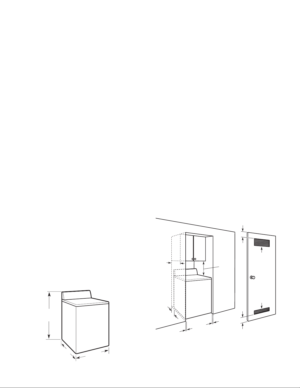
LOCATION REQUIREMENTS
Select proper location for your washer to improve performance
and minimize noise and possible “washer walk.” Install your
washer in a basement, laundry room, closet, or recessed area.
Spacing for recessed area or closet installation
All dimensions show recommended spacing allowed, with tested
spacing of 0" (0 mm) clearance on sides.
■ Additional spacing should be considered for ease of
installation and servicing.
■ Additional clearances might be required for wall, door, and
oor moldings.
■ Additional spacing should be considered on all sides of the
washer to reduce noise transfer.
■ For closet installation, with a door, minimum ventilation
openings in the top and bottom of the door are required.
Louvered doors with equivalent ventilation openings are
acceptable.
■ Companion appliance spacing should also be considered.
3"
*
(76 mm)
2
*
*
*
17"
(432 mm)
48 in.
(310 cm2)
44"
(1118 mm)
27.5"
(698 mm)
27.5"
(698 mm)
5"
(126 mm)
* Required spacing
1"
(25 mm)
1"
(25 mm)
3"
*
(76 mm)
2
24 in.
(155 cm2)
*
3
DRAIN SYSTEM
41/2"
(114 mm)
Drain system can be installed using a oor drain, wall standpipe,
oor standpipe, or laundry tub. Select method you need.
Floor standpipe drain system
39"
41/2"
(114 mm)
Minimum diameter for a standpipe drain: 2" (51 mm). Minimum
carry-away capacity: 17 gal. (64 L) per minute. Top of standpipe
must be at least 39" (990 mm) high; install no higher than 96"
(2.44 m) from bottom of washer. If you must install higher than
96" (2.44 m), you will need a sump pump system.
(990 mm)
ELECTRICAL REQUIREMENTS
Wall standpipe drain system
41/2"
(114 mm)
See requirements for oor standpipe drain system.
Floor drain system
Floor drain system requires a Siphon Break Kit (Part Number
285834), 2 Connector Kits (Part Number 285835), and an
Extension Drain Hose (Part Number 285863) that may be
purchased separately. To order, please see toll-free phone
numbers in your “Use and Care Guide.” Minimum siphon break:
28" (710 mm) from bottom of washer. (Additional hoses may
be needed.)
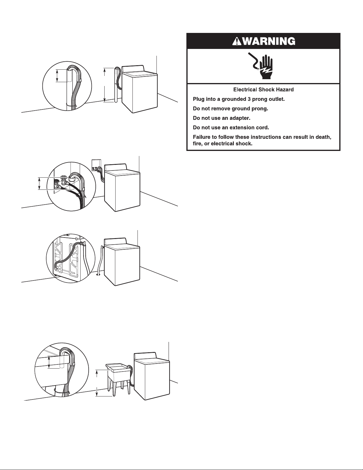
■ A 120 volt, 60 Hz., AC only, 15- or 20-amp, fused electrical
supply is required. A time-delay fuse or circuit breaker on
a separate circuit serving only this washer is recommended.
■ This washer is equipped with a power supply cord having
a 3-prong grounding plug.
■ To minimize possible shock hazard, the cord must be
plugged into a mating, 3-prong, grounding-type outlet,
grounded in accordance with local codes and ordinances.
If a mating outlet is not available, it is the personal
responsibility and obligation of the customer to have the
properly grounded outlet installed by a qualied electrician.
■ If codes permit and a separate ground wire is used, it is
recommended that a qualied electrician determine that
the ground path is adequate.
■ Do not ground to a gas pipe.
■ Check with a qualied electrician if you are not sure
the washer is properly grounded.
■ Do not have a fuse in the neutral or ground circuit.
Laundry tub drain system
30"
39"
(762 mm)
(990 mm)
Minimum capacity: 20 gal. (76 L). Top of laundry tub must be at
least 39" (990 mm) above oor; install no higher than 96" (2.44 m)
from bottom of washer.
IMPORTANT: To avoid siphoning, no more than 4 ½" (114 mm)
of drain hose should be inside standpipe or below the top of
wash tub. Secure drain hose with cable tie.
4
INSTALLATION INSTRUCTIONS
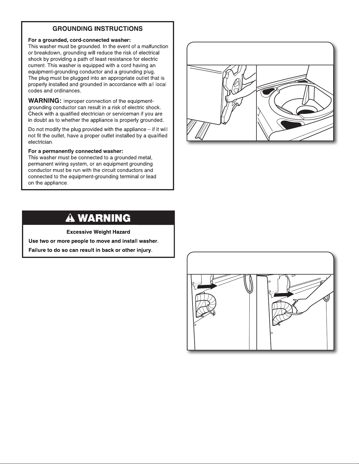
REMOVE SHIPPING BASE
AND PACKING RING
1. Remove shipping base
and packing ring
Place cardboard supports from shipping carton on oor
behind washer for support. Secure the lid with tape. Using
two or more people, tip the washer onto its back and place
on cardboard supports. Remove foam shipping base. Then,
set washer back upright, and remove the tape from the lid
so that you can open the lid and remove the foam packing
ring from the washer tub.
NOTE: Keep foam packing ring in case you need to move
the washer in the future.
Before you start: remove shipping materials.
It is necessary to remove all shipping materials for proper
operation and to avoid excessive noise from washer.
NOTE: To avoid oor damage during installation, set the washer
onto cardboard before moving across the oor.
IMPORTANT:
■ Be sure the foam shipping base has been removed from the
bottom of the washer as directed in the “Remove Shipping
Base and Packing Ring” section.
■ If foam shipping base has not been removed, be sure lid is
secured with tape before laying washer on its back.
■ Removing the foam shipping base is necessary for proper
operation.
CONNECT DRAIN HOSE
IMPORTANT: Proper connection of the drain hose helps
to avoid water leakage and damage to your oors. The drain
hose is connected to your washer and is stored inside the
washer cabinet.
1.
Remove drain hose from washer
cabinet
Gently pull hose out of back of washer cabinet from top until
end emerges.
IMPORTANT: Do not force excess drain hose back into rear
of washer.
5

2. Connect drain hose form
For a laundry tub or standpipe drain, connect the drain hose
form. For a oor drain, do not install drain hose form. You
may need alternate parts with separate directions. See
“Tools and Parts” to determine what you may need.
Feed hose into one end of form. Bend hose and feed through
other side, anchoring form on smooth sections of hose. The
hose must extend 4.5" (114 mm) beyond the form.
3. Place drain hose in standpipe
CONNECT INLET HOSES
Insert new at washers
1.
A B
A. Coupling
B. Washer
IMPORTANT: To avoid leaks, check that your water inlet
hoses have at washers at both ends. Washer must be
connected to water faucets with new inlet hoses with at
washers (not provided). Do not use old hoses. Do not use
hoses without washers.
Connect inlet hoses to water
2.
faucets
4.5"
(114 mm)
Place hose into standpipe (shown in picture) or over side
of laundry tub.
IMPORTANT: To keep drain water from going back into
the washer:
■ Do not force excess drain hose into standpipe. Hose
should be secure but loose enough to provide a gap
for air.
■ Do not lay excess hose on the bottom of the laundry
tub.
Make sure the washer basket is empty. Attach the hose
labeled hot to hot water faucet. Screw on coupling by hand
until it is seated on washer. Use pliers to tighten couplings
an additional two-thirds turn. Repeat this step with the hose
labeled cold for the cold water faucet. Both hoses must
be connected for washer to work properly.
IMPORTANT: Do not overtighten or use tape or sealants
on valve when attaching to faucets or washer. Damage
can result.
HELPFUL TIP: Make note of which hose is connected
to hot water to help in attaching hoses to washer correctly.
3. Clear water lines
Run water for a few seconds through hoses into a laundry
tub, drainpipe, or bucket to avoid clogs. Water should run
until clear. Check the temperature of the water to make sure
that the hot water hose is connected to the hot water faucet
and the cold water hose is connected to the cold water faucet.
6
 Loading...