

Whirlpool WTW5500XL1 Installation Guide
WASHER INSTALLATION INSTRUCTIONS
INSTRUCTIONS POUR L’INSTALLATION DE LA LAVEUSE
Table of Contents Table des matières
WASHER SAFETY ..............................................................1
INSTALLATION REQUIREMENTS .....................................2
Tools and Parts ..................................................................... 2
Location Requirements .......................................................2
Drain System ........................................................................ 3
Electrical Requirements ......................................................4
INSTALLATION INSTRUCTIONS .......................................4
Connect Drain Hose ............................................................. 5
Connect Inlet Hoses ............................................................. 6
Level Washer ........................................................................7
Complete Installation Checklist .......................................... 8
Para obtener acceso al instrucciones de instalación en español, o para obtener información adicional acerca
de su producto, visite: www.whirlpool.com
INSTALLATION NOTES
Date of purchase: _________________________________
Date of installation: _______________________________
Installer: ________________________________________
Model number: ___________________________________
Serial number: ___________________________________
SÉCURITÉ DE LA LAVEUSE .............................................9
EXIGENCES D’INSTALLATION .........................................9
Outillage et pièces ................................................................. 9
Exigences d’emplacement ................................................. 10
Système de vidange ............................................................. 11
Spécications électriques ................................................... 11
INSTRUCTIONS D’INSTALLATION .................................12
Raccordement du tuyau de vidange...................................13
Raccordement des tuyaux d’arrivée d’eau ........................ 14
Établissement de l’aplomb de la laveuse ........................... 15
Liste de vérication pour l’achèvement de l’installation .. 16
NOTES SUR L’INSTALLATION
Date d’achat : ____________________________________
Date d’installation : _______________________________
Installateur : _____________________________________
Numéro de modèle : _______________________________
Numéro de série : _________________________________
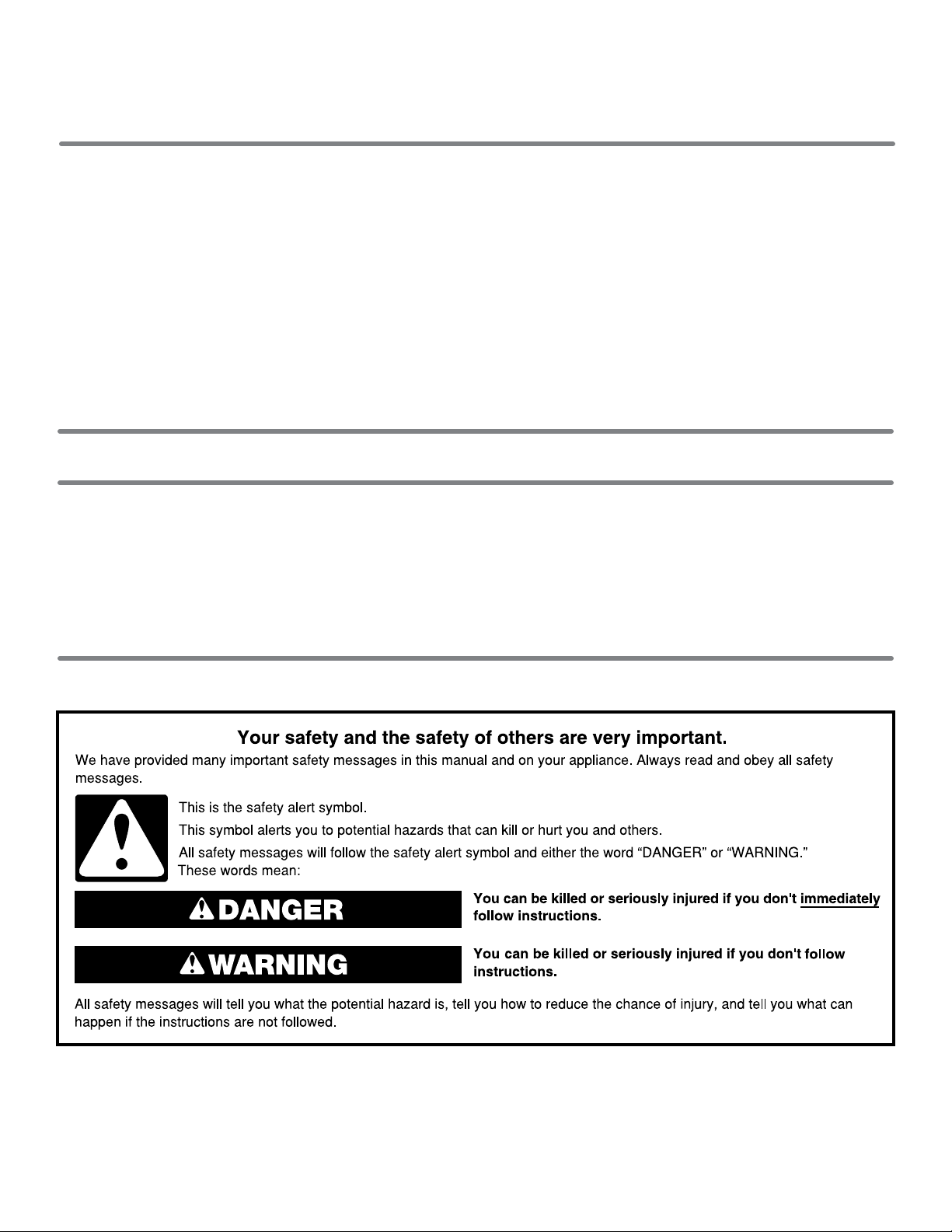
WASHER SAFETY
W10240509E
W10240510E-SP
INSTALLATION REQUIREMENTS
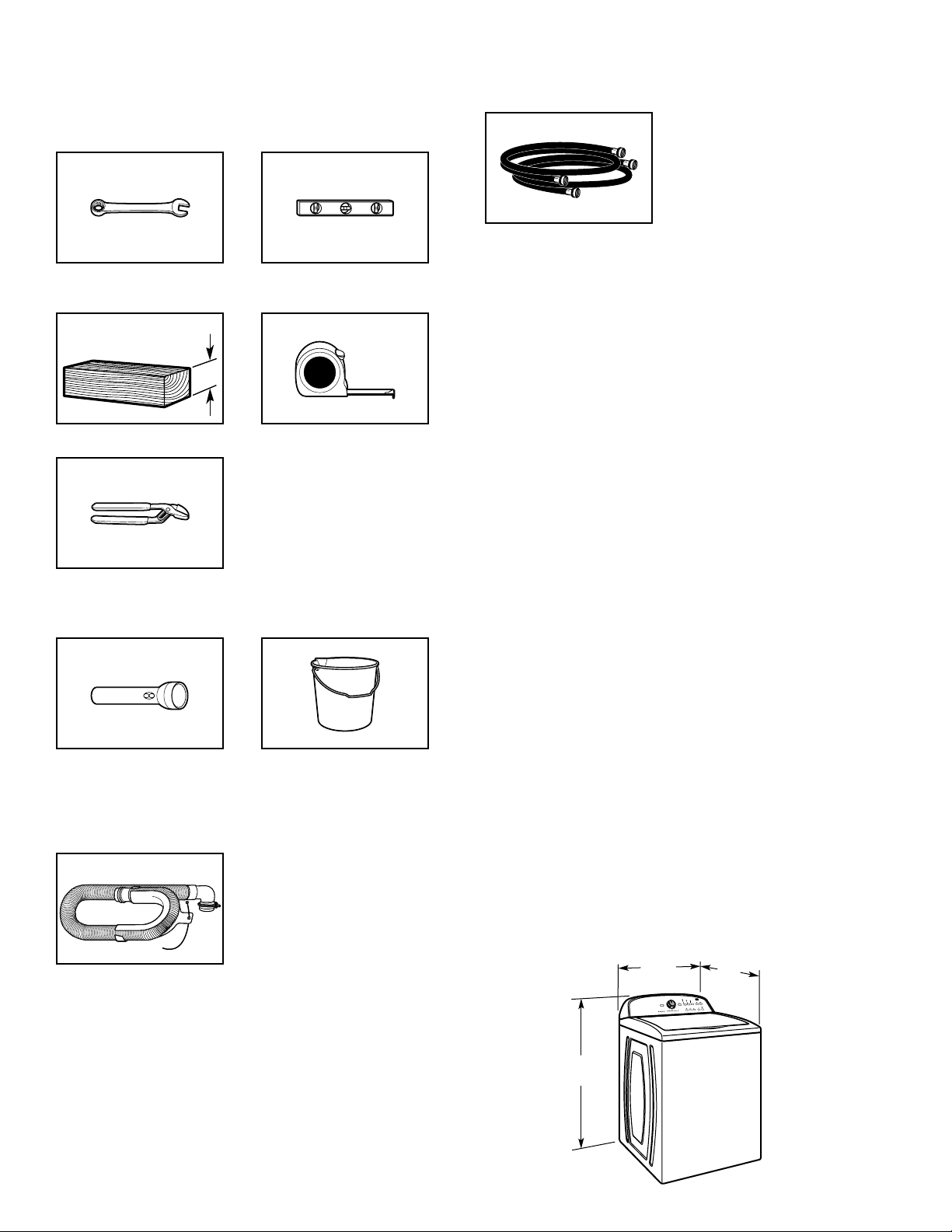
Tools and Parts
Gather required tools and parts before starting installation.
Tools needed:
Adjustable or open end
wrench
9
/16" (14 mm)
Level
4" min
(102 mm)
Wood block
Pliers that open to
3
⁄4" (44.5 mm)
1
Optional tools:
Flashlight Bucket
Parts supplied:
NOTE: All parts supplied for installation are in
cardboard insert in the top of the washer.
Ruler or measuring tape
Parts needed: (Not supplied with washer)
Inlet hoses with
flat washers
To order, please refer to toll-free phone numbers on back page
of your Use and Care Guide.
n
8212656RP 10 ft. (3.0 m) Inlet hose, Black EPDM (2 pack)
n
8212641RP 5 ft. (1.5 m) Inlet hose, Black EPDM (2 pack)
n
8212646RP 4 ft. (1.2 m) Inlet hose, Black EPDM (2 pack)
n
8212545RP 5 ft. (1.5 m) Inlet hose, Red and Blue EPDM
(2 pack)
n
8212487RP 5 ft. (1.5 m) Nylon braided inlet hose (2 pack)
n
8212638RP 6 ft. (1.8 m) Nylon braided inlet hose, space
saving 90° elbow, hypro-blue steel couplings
(2 pack)
n
8212637RP 6 ft. (1.8 m) Inlet hose, Black EPDM, space
saving 90° elbow, hypro-blue steel couplings
(2 pack)
Alternate parts: (Not supplied with washer)
Your installation may require additional parts. To order, please
refer to toll-free numbers on back page of your Use and Care
Guide.
If you have: You will need:
Overhead sewer Standard 20 gal. (76 L) 39" (990 mm)
tall drain tub or utility sink, sump
pump and connectors (available from
local plumbing suppliers)
1" (25 mm) standpipe 2" (51 mm) diameter to 1" (25 mm)
diameter Standpipe Adapter
Part Number 3363920
Connector Kit Part Number 285835
Drain hose too short Extension Drain Hose Part
Number 285863
Connector Kit Part Number 285835
Lint clogged drain Drain Protector Part Number 367031
Connector Kit Part Number 285835
Drain hose with clamp,
U-form, and cable tie
2
LOCATION REQUIREMENTS
Select proper location for your washer to improve performance
and minimize noise and possible “washer walk”. Install your
washer in a basement, laundry room, closet, or recessed area.
1
/2"
43"
42"
(1092 mm)
(1067 mm)
27
(699 mm)
27"
(686 mm)
You will need:
3"
(25 mm)
4.5"
(114 mm)
n
A water heater set to 120° F (49° C).
n
A grounded electrical outlet located within 4 ft (1.2 m) of
power cord on back of washer.
n
Hot and cold water faucets located within 3 ft (0.9 m) of hot
and cold water ll valves on washer, and water pressure
of 20-100 psi (138-690 kPa).
n
A level oor with maximum slope of 1" (25 mm) under entire
washer. Installing on carpet is not recommended.
n
Floor must support washer’s total weight (with water and load)
of 315 lbs (143 kgs).
IMPORTANT: Do not install, store, or operate washer where it will
be exposed to weather or in temperatures below 32° F (0° C).
Water remaining in washer after use may cause damage in low
temperatures. See “Washer Care” in your Use and Care Guide
for winterizing information.
Proper installation is your responsibility.
Recessed area or closet installation
(76 mm)
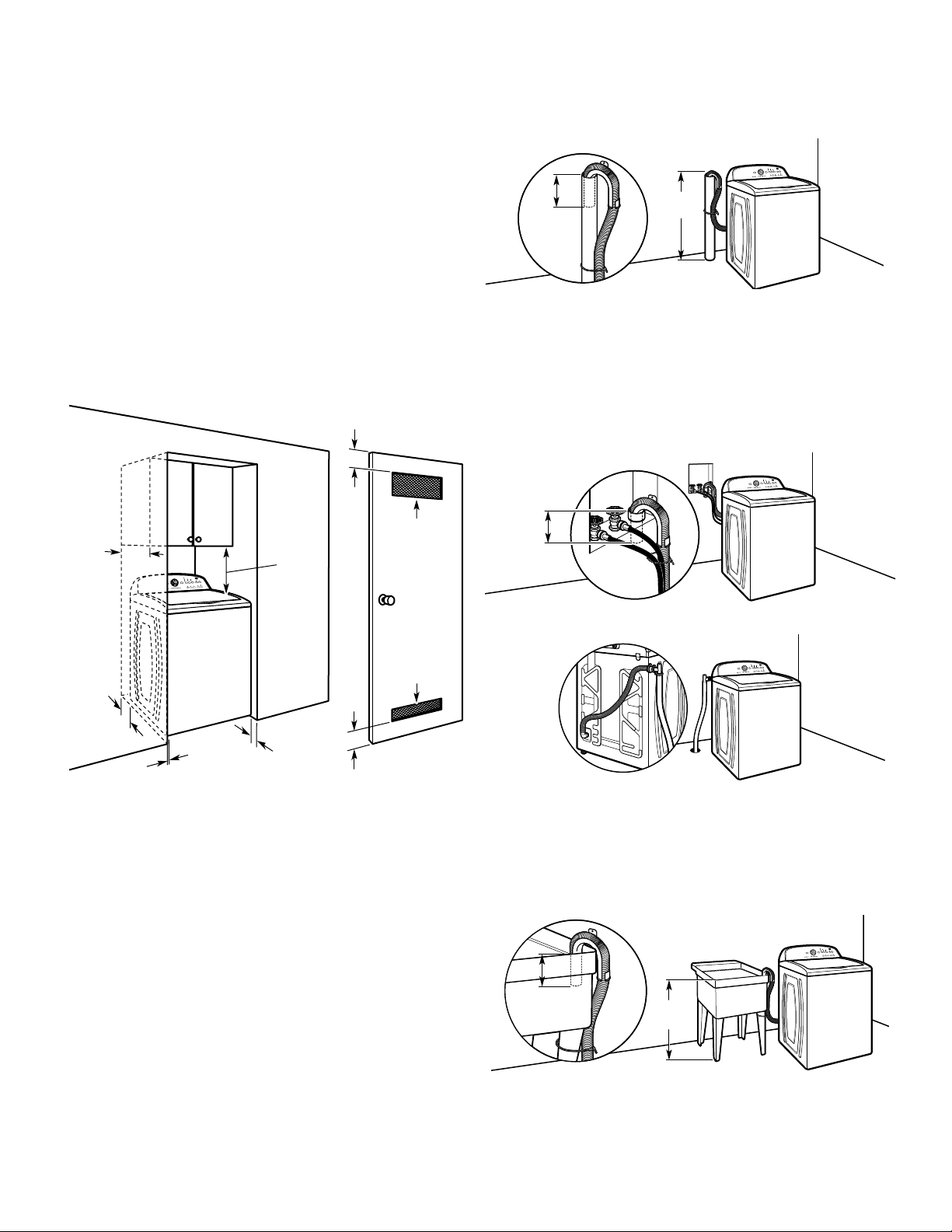
DRAIN SYSTEM
Drain system can be installed using a oor drain, wall standpipe,
oor standpipe, or laundry tub. Select method you need.
Floor standpipe drain system
39"
4.5"
(114 mm)
Minimum diameter for a standpipe drain: 2" (51 mm). Minimum
carry-away capacity: 17 gal. (64 L) per minute. Top of standpipe
must be at least 39" (990 mm) high; install no higher than
96" (2.44 m) from bottom of washer. If you must install higher
than 96" (2.44 m), you will need a sump pump system.
It is the responsibility of the installer to install and secure the
drain hose into the provided plumbing/drain in a manner that
will avoid the drain hose coming out of or leaking from the
plumbing/drain.
Wall standpipe drain system
(990 mm)
14" max.
(356 mm)
5"
(126 mm)
1"
17"
(432 mm)
1"
(25 mm)
3"
(76 mm)
2
48 in.
(310 cm2)
2
24 in.
(155 cm2)
Dimensions show recommended spacing allowed, except for
closet door ventilation openings which are minimum required.
This washer has been tested for installation with spacing of
0" (0 mm) clearance on the sides. Consider allowing more space
for ease of installation and servicing, and spacing for companion
appliances and clearances for walls, doors, and oor moldings.
Add spacing of 1" (25 mm) on all sides of washer to reduce
noise transfer. If a closet door or louvered door is installed,
top and bottom air openings in door are required.
4.5"
(114 mm)
See requirements for oor standpipe drain system.
Floor drain system
Floor drain system requires a Siphon Break Kit (Part Number
285834), 2 Connector Kits (Part Number 285835), and an
Extension Drain Hose (Part Number 285863) that may be
purchased separately. To order, please see toll-free phone
numbers in your Use and Care Guide. Minimum siphon break:
28" (710 mm) from bottom of washer. (Additional hoses may
be needed.)
Laundry tub drain system
39"
(990 mm)
Minimum capacity: 20 gal. (76 L). Top of laundry tub must be at
least 39" (990 mm) above oor; install no higher than 96" (2.44 m)
from bottom of washer.
IMPORTANT: To avoid siphoning, no more than 4.5" (114 mm)
of drain hose should be inside standpipe or below the top of
wash tub. Secure drain hose with cable tie.
3
 Loading...