

Whirlpool WRX-17TM Service Manual
Model: Version: 12NC:
WRX-17TM WRX48FSBFW00 (Silver color)
Whirlpool LAR - Home Appliances Division MSEX0000i
International Business – SKIC 1st Edition
Prepared by Luciano Cidral January, 2008
Reviewed by Alvaro S Alcântara January, 2008
1

INDEX
1. INTRODUCTION ......................................................................................................................................................3
2. PRESENTATION......................................................................................................................................................3
3. CONCEPT & TECHNOLOGY ..................................................................................................................................3
3.1. ELECTRONIC SYSTEM ...................................................................................................................................3
3.2. AIR FLOW SYSTEM .........................................................................................................................................4
3.3. FUNCTIONS......................................................................................................................................................5
3.3.1. Adaptive Defrost ........................................................................................................................................5
4. MAIN COMPONENTS..............................................................................................................................................6
4.1. COOLING CIRCUIT ..........................................................................................................................................6
4.1.1. Compressor & Acessories .........................................................................................................................6
4.1.2. Condenser .................................................................................................................................................6
4.1.3. Evaporator .................................................................................................................................................7
4.2. DEFROST SYSTEM .........................................................................................................................................7
4.2.1. Defrost Heater............................................................................................................................................7
4.2.2. Defrost sensor............................................................................................................................................7
4.2.3. Thermofuse................................................................................................................................................8
4.3. FREEZER FAN MOTOR...................................................................................................................................8
4.4. REFRIGERATOR FAN MOTOR .......................................................................................................................8
4.5. ELECTRONIC CONTROL.................................................................................................................................8
4.6. INTERFACE BOARD (LCD DISPLAY) .............................................................................................................9
5. TESTS ......................................................................................................................................................................9
5.1. INITIAL TEST ROUTINE (FACTORY ROUTINE).............................................................................................9
5.2. SERVICE TEST ROUTINE .............................................................................................................................10
5.3. SENSOR .........................................................................................................................................................11
5.4. ALARM SYSTEM ............................................................................................................................................12
5.4.1. Party Mode time exceeded ......................................................................................................................12
5.4.2. Temperature Alarm ..................................................................................................................................13
5.4.3. Open door ................................................................................................................................................13
5.5. TECHNICAL TROUBLESHOOTING...............................................................................................................13
6. REQUIRED TOOLS ...............................................................................................................................................16
7. ASSEMBLAGE & DISMOUNT ..............................................................................................................................16
7.1. ELECTRONIC CONTROL...............................................................................................................................16
7.2. INTERFACE BOARD – LCD DISPLAY...........................................................................................................17
7.3. LAMP SWITCH ...............................................................................................................................................18
7.4. AIR DIFFUSER................................................................................................................................................19
7.5. EVAPORATOR ...............................................................................................................................................20
7.6. SENSORS (REFRIGERATOR, FREEZER & DEFROST) ..............................................................................21
7.7. DOOR REVERSAL .........................................................................................................................................22
2

1. INTRODUCTION
This following manual objectives give you general information that will allow you can evaluate and do
interventions in whole product family.
Specific information like values of electrical and mechanical specifications, diagrams must be consulted in the
Technical Data, sent by specific markets product codes. To Spare Parts and Exploded Views, consult the Spare
Parts List.
Instructions of working and installation must be consulted in the customer manual (Users Guide).
2. PRESENTATION
Their main characteristics are: Easy Ice system with automatic feeder, External handle, Door cooling system,
Can rack & Skin condenser (Clinched condenser).
1- Refrigerator light
2- Shelves
2a- Bottle holder (depending on model)
3- Crisper drawer
3a- Moisture control
4- Door trays
5- Removable bottle holder
6- Can holder (depending on model)
6a- Multiflow outlets
7- Crisper drawer divider (depending on
model)
8- Divider (depending on model)
9- Ice maker (depending on model)
10- Freezer shelves (depending on
model)
11- Egg tray
12- Freezer compartment door
13- Freezer compartment door trays
14- Fresh control compartment
C- Anti-bacterial filter (depending on
model)
Attention:
The anti-bacterial filter assures a higher level of hygiene in the refrigerator through continuous purifying the air
of bacteria. Remove it from the box (found in the crisper drawer) and insert into the grille in the back wall of the
refrigerator compartment (item C). Replace the filter every 6 months.
3. CONCEPT & TECHNOLOGY
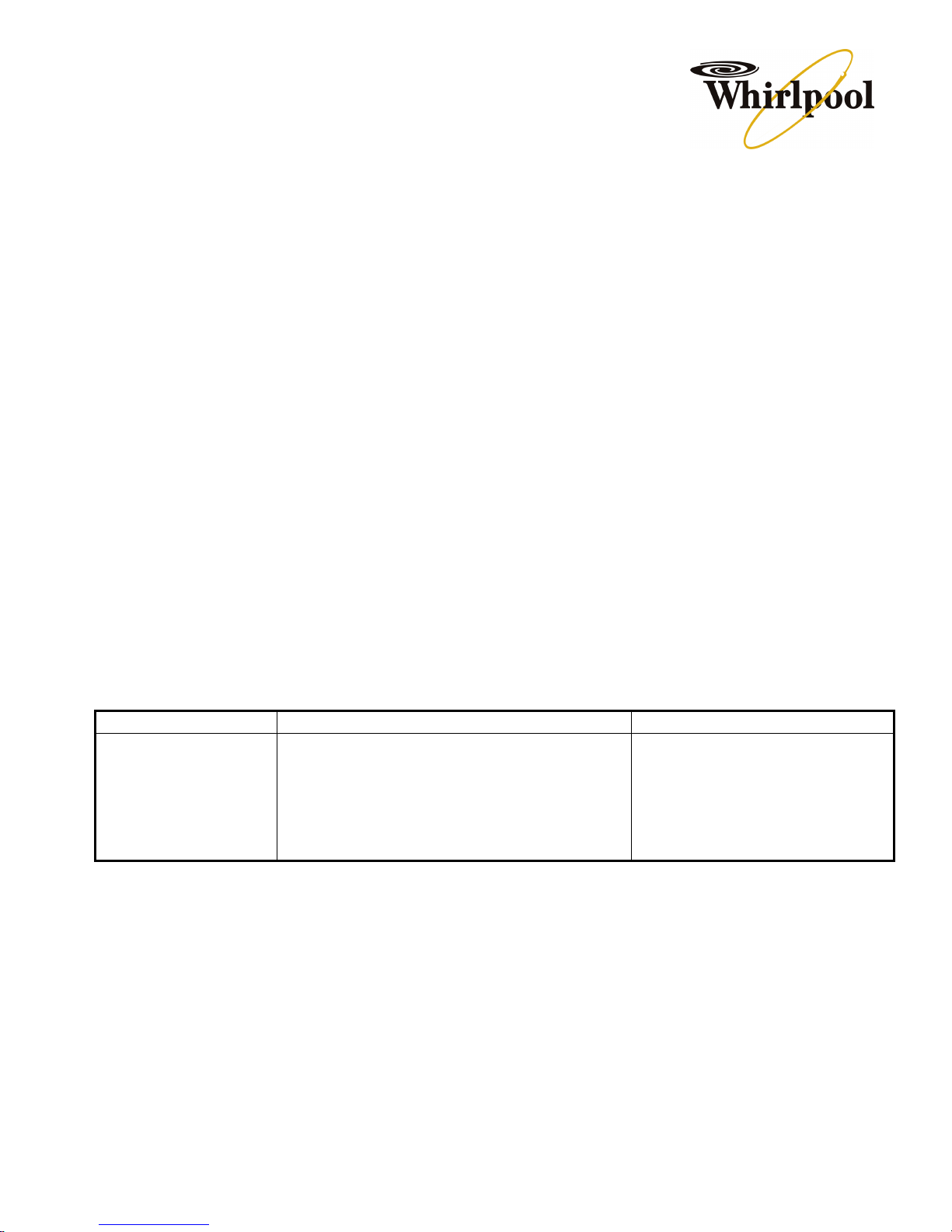
3.1. Electronic System
This is a no frost refrigerator managed by an electronic system, assisted by some peripherical components, as
follows:
- Electronic control;
- Interface board;
- Reed-switch board;
- Temperature sensors (Refrigerator , freezer & defrost);
- Compressor;
- Freezer Fan Motor (V dc);
- Refrigerator Fan Motor (V dc);
- Defrost Heater;
- Lamps.
3
Basically, the temperature read inside the freezer by the temperature sensor is sent to the electronic control,
which controls the working of the compressor, of the fan motor, and of the heater (each 8 hours of working of
the compressor (or each 4 fours in the adaptive mode, as you will see following this manual).
Variables:
a) The internal lamp is lighted when the door is opened. An electromechanical switch is connected in series
between the lamp and the electronic control.
b) The temperature inside the refrigerator compartment is controlled by an mechanical thermostatic damper,
which controls the air flow from the freezer to the refrigerator compartment, therefore, the changed air from
the refrigerator compartment rises till the temperature sensor located on the freezer. The factor which
defines when will occurs a defrost procedure, is therefore, strongly linked to the quantity of the opening of
doors, besides the quantity of food and external temperatures.
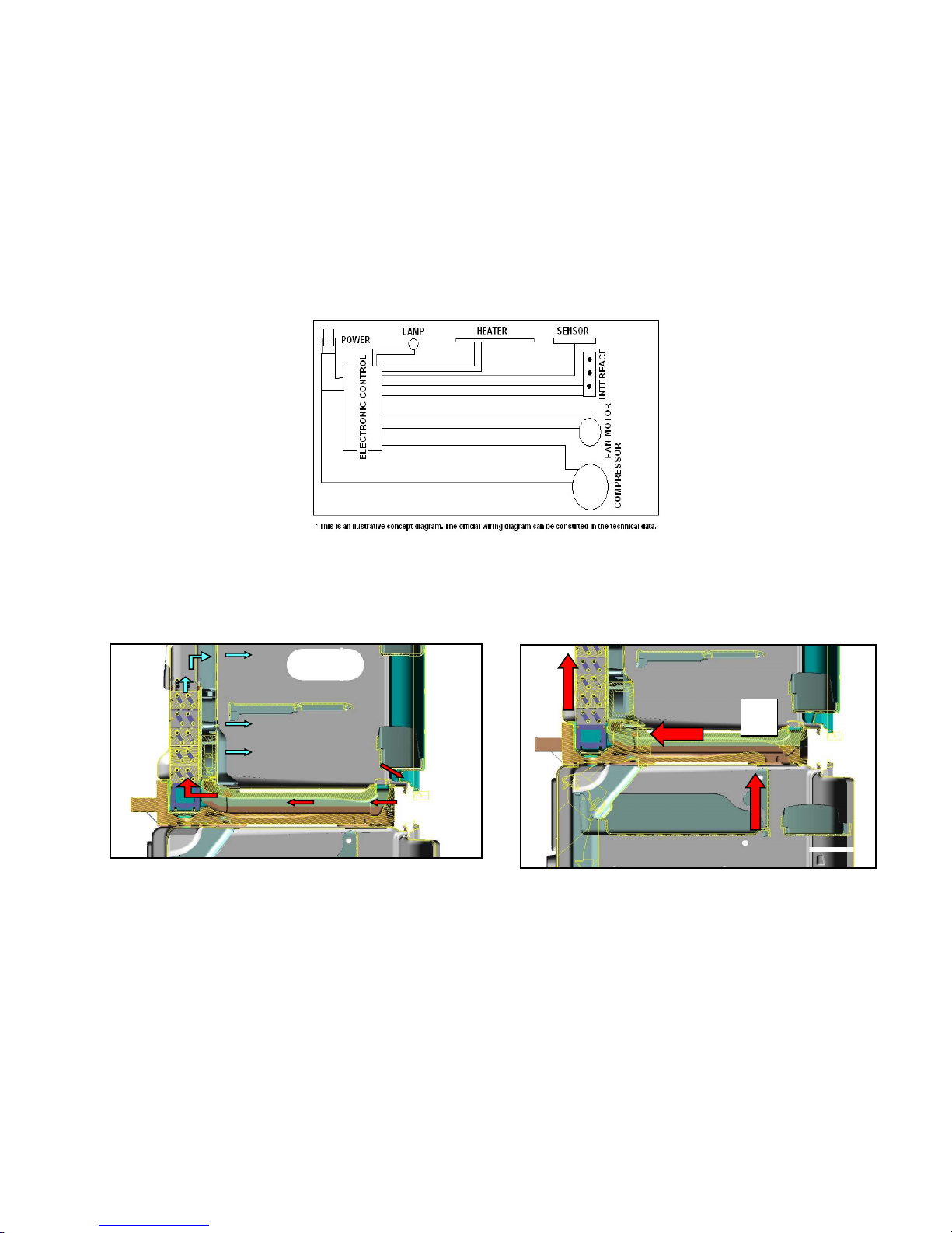
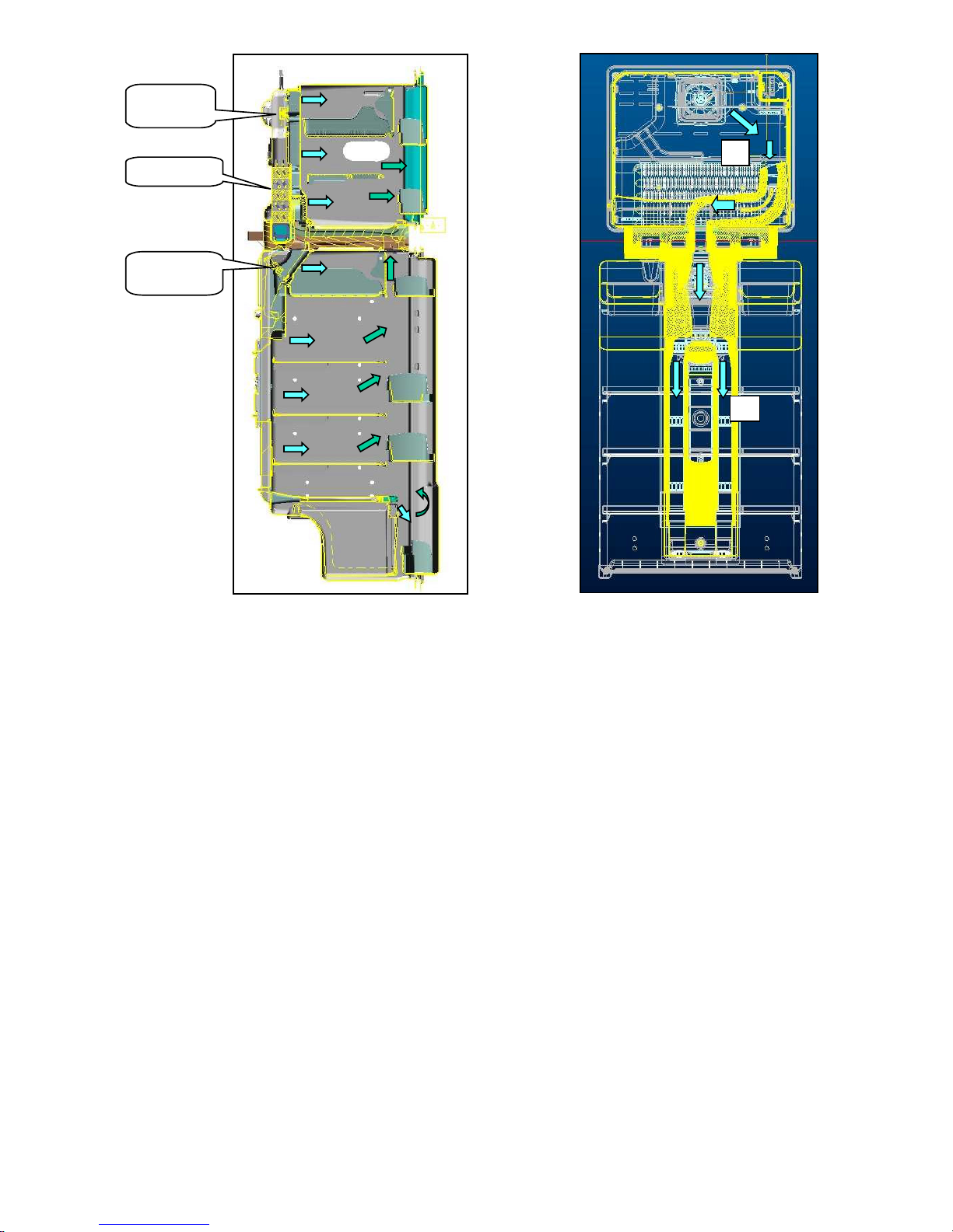
3.2. Air Flow System
The pictures below show us how the forced air, circulates on the product, and returns to the evaporator, when
suffers the cooling process again.
3
4
Freezer
1
2
Fan Motot
Evaporator
Thermostatic
Damper
The refrigerator air diffuser has a wind flow system, which provide a better air distribution over this compartment
due to the many outlets/windows available.
Protected by a front plastic cover, the air diffuser is made of styrofoam (expanded polyesthyrene - EPS). the
upper part houses the damper and the diffuser complement, whereas the rear portion is provided with several
seals to prevent air leaking through the sides
3.3. Functions
3.3.1. Adaptive Defrost
This refrigerator has an adaptive defrost system, which is adjustable according to client’s habits, environmental
conditions, etc.
Monitored by the electronic control, this system is constituted of the following components:
- Electronic control;
- Defrost heater;
- Defrost sensor temperature;
- Defrost gutter;
- Evaporation recipient (above the compressor).
The accurate frequency is defined by the electronic control throughout the following monitoring:
- Compressor activity time;
- Door opening frequency;
- Time of the last executed defrosts;
5

Defrosts shall occur in every 4 hours (of the compressor activity), able to be reduced (adaptive) to every 4 hours
(of the compressor activity) according to the usage (determined by the electronic control software). Defrost
average time is from 10 to 20 min. And the maximum is 40 min., Afterwards, the product will return to its normal
operation.
Summarily, the electronic control activates the defrost system, which will execute the following steps:
- Fan motor and compressors are turned-off;
- Heater is activated;
- Defrost sensor informs the defrost ending when reach 15°C (or 40 minutes, maximum time);
- Heater is turned-off;
- Compressor is turned on after 5 minutes the heater is off;
- Motor fan is turned on when the differential of temperature between defrost and freezer sensors reach
2°C;
- Product returns to the programmed function before defrost.
This defrost system has also a safety system which will put in action an immediate defrost in case of an existing
differential temperature between defrost sensor and freezer sensor higher than 10°C for 10 minutes, helping
contend against casual ice building up on the evaporator.
When the product is with fast freezing mode enable, the defrost system will be fixed and not adaptive, and 2
defrosts will occur during this period, it means, the first will occur 3 hours after the compressor activity and the
second just 9 hours after (compressor activity) the first defrost.
Upon ending the activity of the fast freezing function (18 hours), the next defrost cycles will occur as adaptive
normal cycles.
4. MAIN COMPONENTS
4.1. Cooling Circuit
4.1.1. Compressor & Acessories
Alternative hermetic and high efficient compressor, made by Embraco, to refrigerant R134a.
Remark: The compressor just works again when we have 7 minutes since its last cycle.
The relay and thermal protector are sold together the compressor, if necessary to change individually, consult
the spare parts list.
This compressor also has a capacitor (located on the electronic control box). Its function is help the compressor
works efficient and not to execute start-up.
The filter dryer to R134a is a filter with higher quantity of drier element. You can use a filter to R134a in systems
R12, but the inverse is not allowed.
To other information, norms and procedures, consult specific manuals to hermetic system interventions.
4.1.2. Condenser
This refrigerator has a new concept of built-in condenser, which is known as the “clinched”.
Different of a traditional built in condenser (which are inside the cabinet and in contact with another metallic
surface – by others manufacturers), the clinched condenser changes temperature direct to the ambient,
increases the yield, because its contact area is larger.
As this condenser does not be changed, like a normal condenser, it is necessary clean it very well when occurs
interventions on the hermetic systems. Use nitrogen pressure and/or the refrigerant gas (to severe
contamination).
6
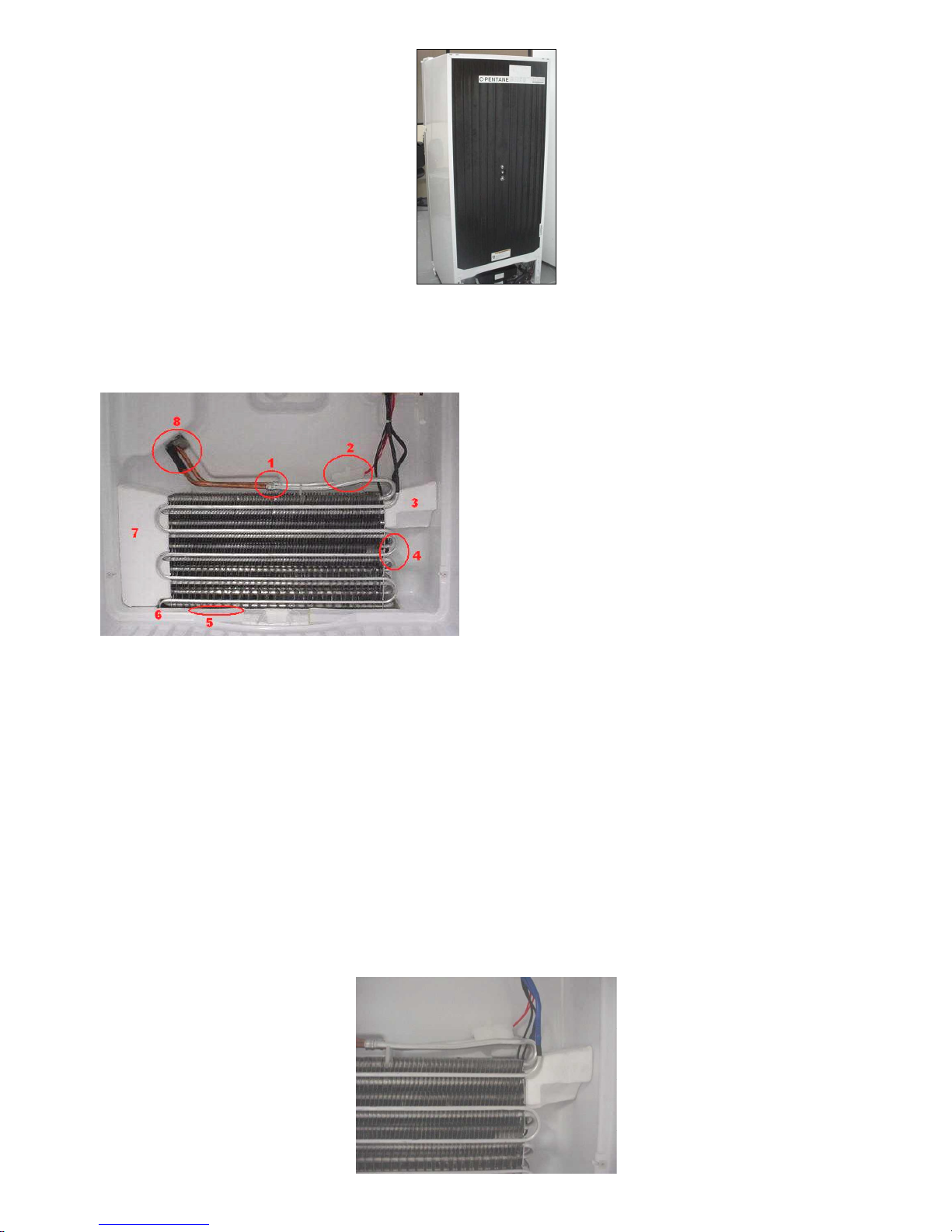
4.1.3. Evaporator
Frost Free Type Evaporator, with suction line injected in the cabinet. Only the Evaporator can be substituted.
Due the internal configuration we strongly recommend do the interventions with the lokring connections.
1. Lokring connector
2. Defrost sensor
3. EPS - shim right
4. Thermofuse
5. Defrost shield
6. Deforst heater
7. EPS - shim left
8. Suction line
4.2. Defrost System
4.2.1. Defrost Heater
The Defrost Heater involves all the evaporator extension, presenting a better performance of the system. Its
operation (on/off) is also commanded by the electronic control and its electrical features are: Power 275(W),
value 194 to 227 ohms.
The lower part of the defrost heater is fixed at the defrost gutter through claws in order to avoid ice building on
this place. Always ensure the contact between these parts.
4.2.2. Defrost sensor
It’s located at the freezer compartment, along with the evaporator returning pipe. The defrost sensor is
responsible for sending signs to the electronic control, which will command the ending of the adaptive defrost,
turning off the defrost heater, containing a similar function to the well-known defrost bimetal.
7
4.2.3. Thermofuse
Turned on in series connection with the heater defrost, the thermofuse protects the product and does not allow
that defrost heater be turned on continuously in case of failure of the defrost sensor. In case of failures in the
defrost system when the heater is continuously working, it will open at the range of 72 °C to 77 °C.
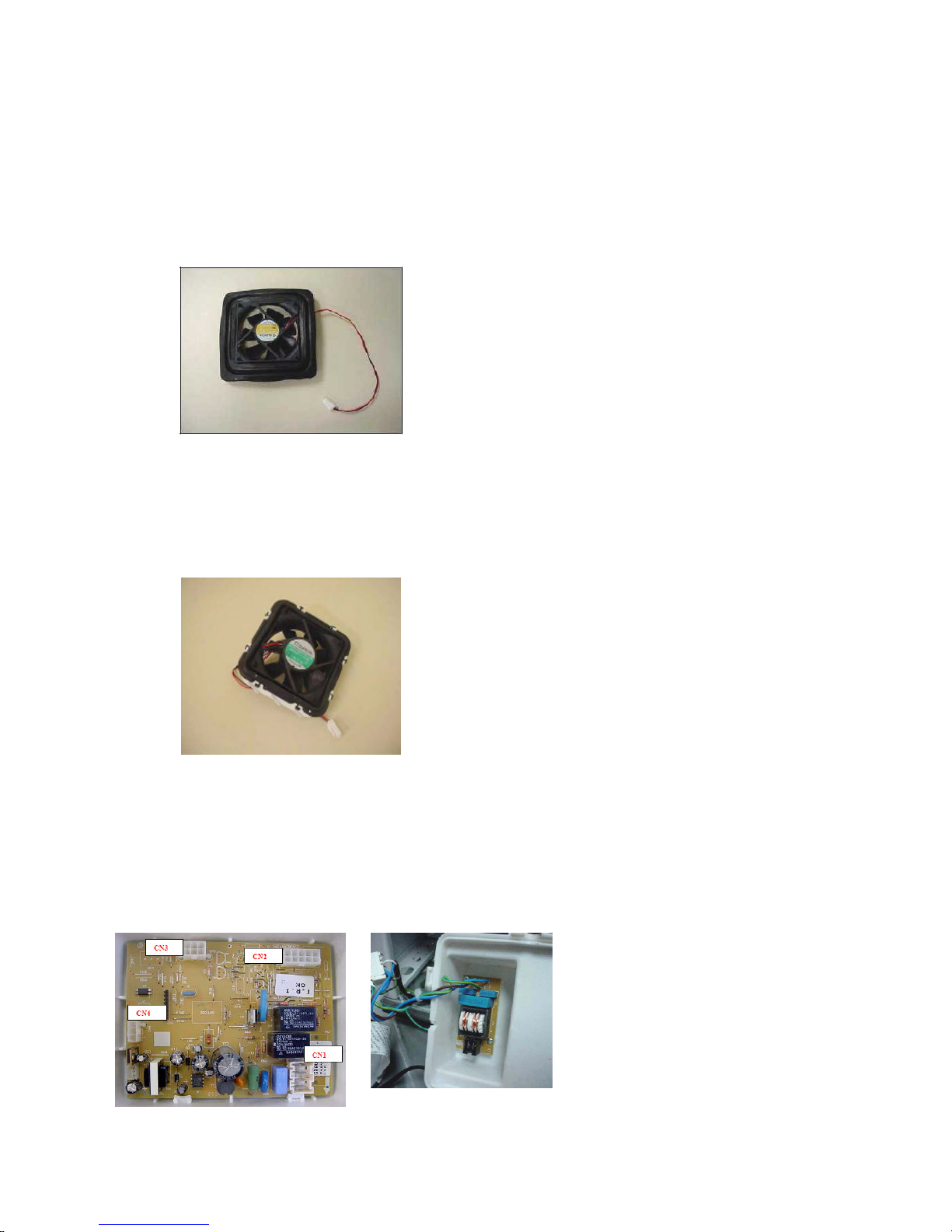
4.3. Freezer Fan Motor
The Fan motor is a (V dc) motor and is fixed to the rear cover of the evaporator through a rubber flexible holder
(freezer), that protects from occasional vibrations, and consequently noise.
Technical Characterístics:
Rated voltage: 24 Vdc
Operating range : 20,4 Vdc - 27,6 Vdc
Current max (a): 0,18 a
Potency max: 4,3 W
Speed rated: 3000 rpm
4.4. Refrigerator Fan Motor
The Refrigerator fan motor is also fed by direct voltage (V dc), therefore, located inside the wind flow, fixed
to a plastic housing by flexible rubber holder, which avoids occasional vibrations and consequently noise. it is
responsible for the forced air circulation inside the refrigerator compartment.
Technical Characterístics:
Rated voltage: 24 Vdc
Operating range : 20,4 Vdc - 27,6 Vdc
Current max (a): 0,1 a
Potency max: 2,9 W
Speed rated: 2900 to 3500 rpm
4.5. Electronic Control
The complete operation of this product is done by the electronic control, which executes the functions according
to the necessities, turning the components on or off through received/managed signals.
Inside its box, the electronic control is divided in 2 parts, a main board and a line filter.
Main board Line filter
CN1 – Compressor and power coard
CN2 – Load components and lamps
CN3 – Temperature sensors
CN4 – Interface board
Note: More details, check the wiring diagram
8
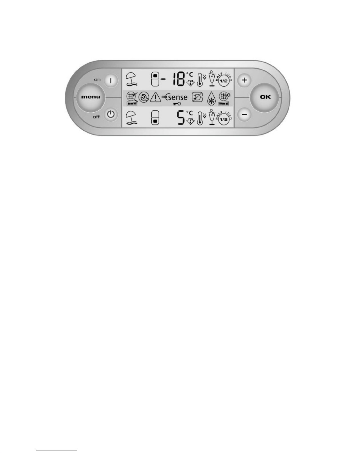
4.6. Interface Board (LCD Display)
The Interface board has the function of interacting with the user, indicating the product functions/programming
and operation (see use characteristics item) always put in operation by the electronic control.
5. TESTS
Two automatic test routines are available in these refrigerators in order to prove the main components of the
product: one executed automatically by the software of the electronic control, when the product is plugged on
the power supply and other handled by the own technician, which are described as follows:
5.1. Initial Test Routine (factory routine)
This refrigerator has an Automatic Testx Routine (works automatically, without manual operation) that is always
executed when the product is energized to the power supply, in order to verify the functioning of the main
components of the product. This routine operates as follow:
# Turn off the product from the wall socket, wait 10 seconds and turn it on again.
Note: At this moment, an inner temperature check will occur in the evaporator, through the Defrost Sensor, and
then the Routine will start automatically.
- The Defrost Heater is energized for 6 seconds
- Freezer Fan Motor is energized for 6 seconds
- Refrigerator Fan Motor is energized for 6 seconds
After 18 seconds, from the result (temperature) gained from the Defrost Sensor, the Electronic Control will
manage the activation of the compressor and fan motors, as follow:
# If the Defrost Sensor is warm (temperature > 0o C)
- Compressor and fans will be energized / turned on.
# If the Defrost Sensor is cold (temperature < 0o C)
- Compressor and fans will not be energized / (will keep off).
After 328 seconds (5.5 minutes) the product is energized, an automatic check will occur for all the Sensors
(Refrigerator, Freezer & Defrost)
# If any of the sensors present failure (open or in short circuit);
- The Automatic Routine will be aborted (348 seconds/ 5.8 minutes); then, after 2 minutes (468
seconds/ 7.8 minutes) the Alarm Code will be shown on the display and the operation proceedings will
follow as described in item – Alarm System.
# In case of no failure is detected
- Product will abort the Automatic Routine (348 seconds/ 5.8 minutes) and starts working in normal
activity, switching on the components due to the necessity (display temperature).
9
 Loading...