

Whirlpool WRS965CIAM User Manual [en, es, fr]

INSTALLATION INSTRUCTIONS
W10168334B
Counter Depth Side by Side Refrigerator
IMPORTANT: READ AND SAVE THESE INSTRUCTIONS. INSTALLATION REQUIRES 2 OR MORE PEOPLE.
INSTRUCCIONES DE INSTALACIÓN
Refrigerador de dos puertas con profundidad de mostrador
IMPORTANTE: LEA Y GUARDE ESTAS INSTRUCCIONES. LA INSTALACIÓN REQUIERE DE 2 O MÁS PERSONAS.
INSTRUCTIONS D’INSTALLATION
Réfrigérateur côte à côte à profondeur de comptoir
IMPORTANT : LIRE ET CONSERVER CES INSTRUCTIONS. L’INSTALLATION NÉCESSITE L’INTERVENTION DE 2 PERSONNES OU PLUS.
Table of Contents / Índice / Table des matières
ASSISTANCE OR SERVICE ............................ 1
REFRIGERATOR SAFETY............................... 2
INSTALLATION REQUIREMENTS ................. 2
Tools and Parts ............................................. 2
Product Dimensions...................................... 3
Location Requirements................................. 4
Electrical Requirements ................................ 5
Water Supply Requirements......................... 5
INSTALLATION INSTRUCTIONS ................... 5
Unpack the Refrigerator................................ 5
Custom Door Panels..................................... 6
Connect Water Supply.................................. 8
Plug in Refrigerator ..................................... 10
Prepare the Water System.......................... 10
Leveling and Door Closing.......................... 11
Door Alignment ........................................... 11
Complete Installation .................................. 11
INSTRUCCIONES DE INSTALACIÓN .......... 12
AYUDA O SERVICIO TÉCNICO.................... 12
SEGURIDAD DEL REFRIGERADOR ............ 12
REQUISITOS DE INSTALACIÓN .................. 13
Piezas y herramientas................................. 13
Medidas del producto................................. 13
Requisitos de ubicación.............................. 15
Requisitos eléctricos................................... 15
Requisitos del suministro de agua.............. 16
INSTRUCCIONES DE INSTALACIÓN .......... 16
Desempaque el refrigerador ....................... 16
Paneles para puerta a la medida................ 17
Conexión del suministro de agua............... 19
Cómo enchufar el refrigerador.................... 21
Preparación del sistema de agua ............... 22
Nivelación y cierre de la puerta................... 22
Alineamiento de la puerta ........................... 23
Complete la instalación............................... 23
INSTRUCTIONS D’INSTALLATION.............. 24
ASSISTANCE OU SERVICE.......................... 24
SÉCURITÉ DU RÉFRIGÉRATEUR................ 24
EXIGENCES D’INSTALLATION .................... 25
Outillage et pièces....................................... 25
Dimensions du produit................................ 25
Exigences d'emplacement ......................... 27
Spécifications électriques........................... 27
Spécifications de l’alimentation en eau...... 28
INSTRUCTIONS D’INSTALLATION.............. 28
Déballage du réfrigérateur .......................... 28
Panneaux de porte personnalisés .............. 29
Raccordement de la canalisation d'eau ..... 31
Brancher le réfrigérateur ............................. 33
Préparer le système d'eau.......................... 34
Nivellement et fermeture de la porte .......... 34
Alignement des portes................................ 35
Achever l’installation ................................... 35
Assistance or Service
If You Have Questions
If you have questions about operating, cleaning or maintaining
your refrigerator, see the User Instructions.
If You Need Service
Maintain the quality built into your refrigerator by calling an
authorized service company.
To locate an authorized service company, see the User
Instructions for the number to call, phone the dealer from whom
you purchased the refrigerator, or check the yellow pages of your
local phone directory.
Keep this book and your sales slip together for future
reference. You must provide proof of purchase or installation
date for in-warranty service.
Write down the following information about your appliance to help
you obtain assistance or service if you ever need it. You will need
to know your complete model number and serial number. You can
find this information on the model and serial number label, located
on the inside wall of the refrigerator compartment.
Dealer name____________________________________________________
Serial number __________________________________________________
Address________________________________________________________
Phone number__________________________________________________
Model number __________________________________________________
Purchase date __________________________________________________
REFRIGERATOR SAFETY
You can be killed or seriously injured if you don't immediately
You
can be killed or seriously injured if you don't
follow
All safety messages will tell you what the potential hazard is, tell you how to reduce the chance of injury, and tell you what can
happen if the instructions are not followed.
Your safety and the safety of others are very important.
We have provided many important safety messages in this manual and on your appliance. Always read and obey all safety
messages.
This is the safety alert symbol.
This symbol alerts you to potential hazards that can kill or hurt you and others.
All safety messages will follow the safety alert symbol and either the word “DANGER” or “WARNING.”
These words mean:
follow instructions.
instructions.
DANGER
WARNING
State of California Proposition 65 Warnings:
WARNING: This product contains one or more chemicals known to the State of California to cause cancer.
WARNING: This product contains one or more chemicals known to the State of California to cause birth defects or other
reproductive harm.
INSTALLATION REQUIREMENTS
Tools and Parts
IMPORTANT:
■ Observe all governing codes and ordinances.
■ Installer: Leave Installation Instructions with homeowner.
■ Homeowner: Keep Installation Instructions for future reference
and for the local electrical inspector’s use.
■ Keep cardboard shipping piece or plywood under refrigerator
until it is installed in the operating position.
■ Comply with installation specifications and dimensions.
■ Remove any moldings or decorative panels from kitchen
cabinets that would not allow access to the refrigerator for
service.
■ Contact a qualified electrical installer.
TOOLS NEEDED (on some models):
Gather the required tools and parts before starting installation.
Read and follow the instructions provided with any tools listed
here.
■ Cordless drill
■ ¹⁄₄" Nut driver
and drill bit
■ Flat-blade
screwdriver
PARTS NEEDED (on some models):
■ Your refrigerator dealer has a kit available with a ¹⁄₄" (6.35 mm)
saddle-type shutoff valve, a union, and copper tubing.
■ Or you can purchase a ¹⁄₄" (6.35 mm) copper tubing with
shutoff valve and a ¹⁄₄" (6.35 mm) compression fitting
(coupling).
■ Depending on water line connections, you may also need a ¹⁄₄"
(6.35 mm) nut and ¹⁄₄" (6.35 mm) ferrule.
■ ⁵⁄₁₆" or adjustable wrench
■ ⁷⁄₁₆" and ¹⁄₂" Open-end wrenches
■ Two adjustable wrenches
■ ³⁄₈" and ¹⁄₂" Socket wrenches
2
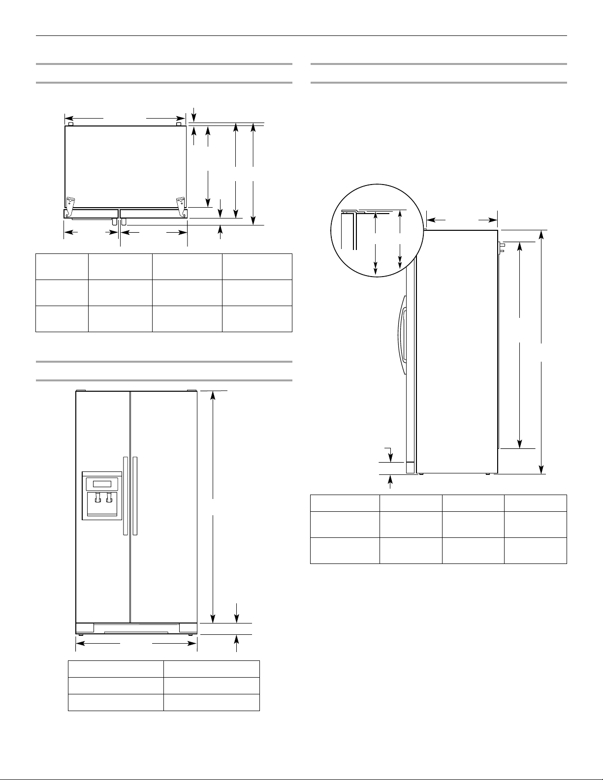
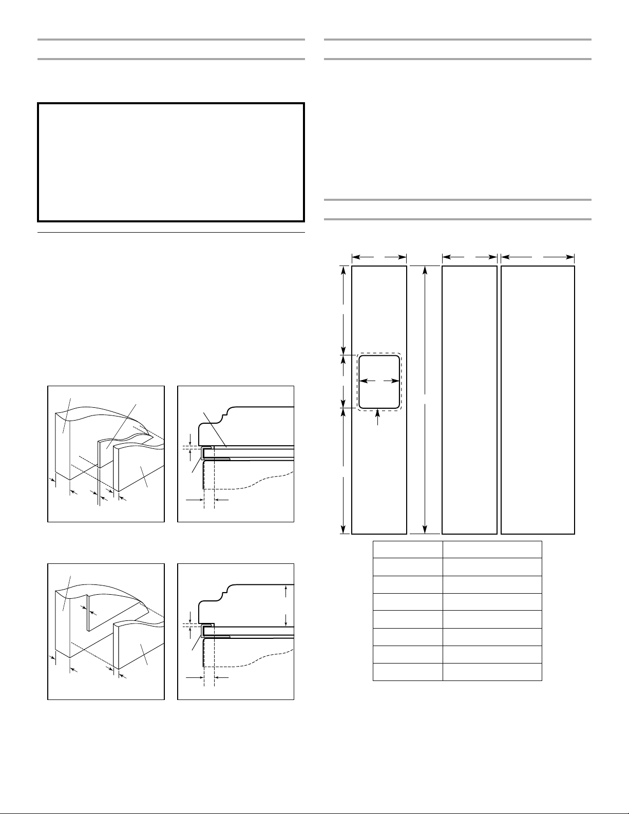
Product Dimensions
A
C
35¹⁄₂"
(90.0 cm)
23⁷⁄₈"
(60.4 cm)
15³⁄₈"
(38.9 cm)
20"
(50.8 cm)
B
⁵⁄₈"
(1.6 cm)
35³⁄₄"
(90.8 cm)
A
3
¹⁄₄"
(8.2 cm)
21³⁄₄"
(55.1 cm)
61¹⁄₄"
(155.6 cm)
3¹⁄₄" (8.2 cm)
C
A
B
Top View
Door
Style
Flat 27¹⁄₂"
Curved 28⁵⁄₈"
*Dimension may vary based on style of door handle.
The depth for the largest available handle is listed.
Depth
A
(69.8 cm)
(72.5 cm)
Depth
B
2⁵⁄₈"(6.5cm)
maximum*
2⁵⁄₈"
(6.5 cm)
30" (76.3 cm)
Depth
C
maximum*
31¹⁄₈"
(79.1 cm)
Side View
■ Height dimensions are shown with the leveling legs extended
to the minimum height of ¹⁄₄" (6.35 mm) below the refrigerator.
NOTE: When leveling legs are fully extended to 1" (25 mm)
below the refrigerator, add ³⁄₄" (19 mm) to the height
dimensions.
■ The power cord is 61¹⁄₄" (155.6 cm) long.
■ The water line attached to the back of the refrigerator is 78"
(198.1 cm) long.
Front View
Model Size Height A Height B Height C
69" 68⁷⁄₈"
(174.8 cm)
72" 71¹⁄₄"
(180.8 cm)
68⁷⁄₈"
(174.9 cm)
71¹⁄₄"
(180.9 cm)
68¹⁄₂"
(174.2 cm)
71"
(180.2 cm)
Model Size Height A
69" 65³⁄₄" (166.9 cm)
72" 68¹⁄₈" (172.9 cm)
3
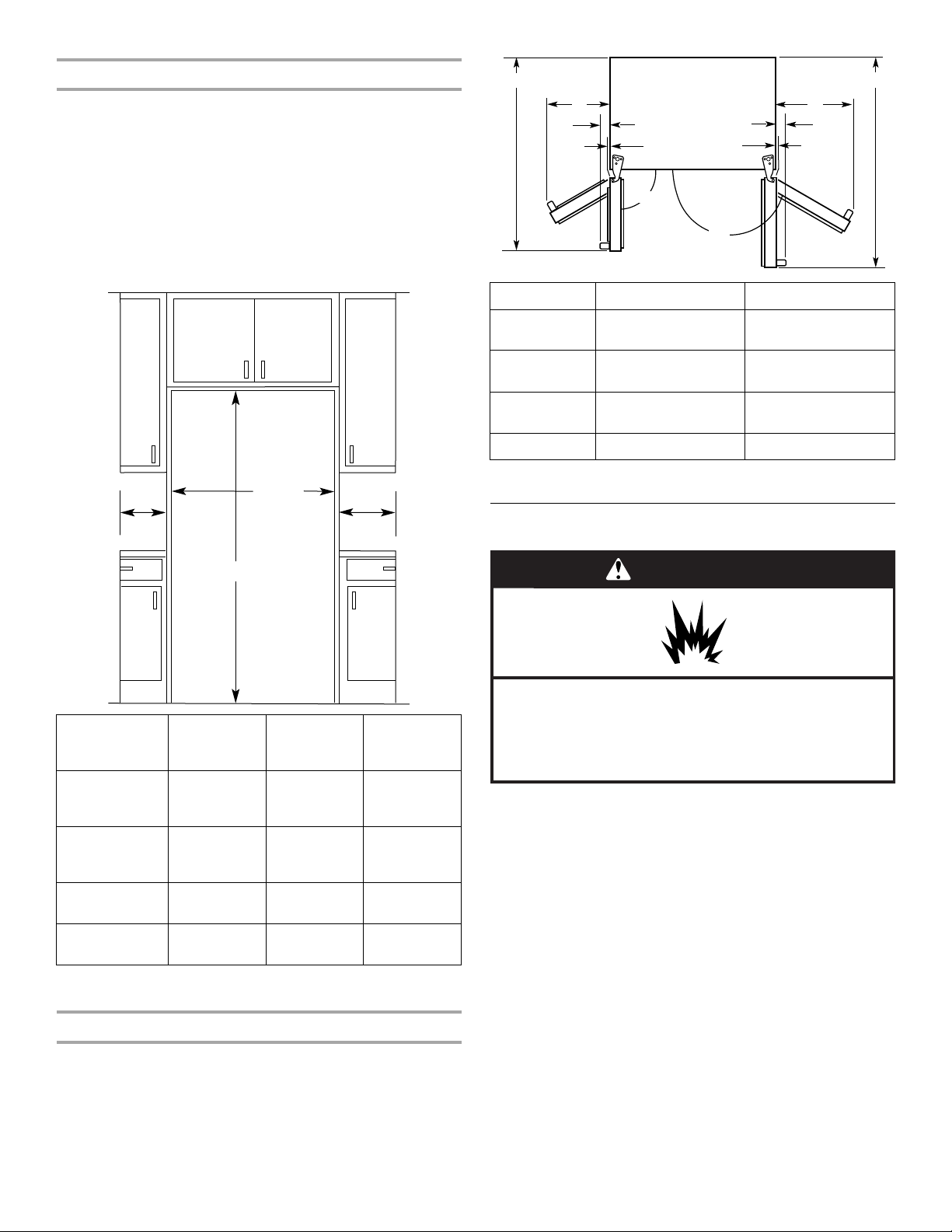
Opening Dimensions
36"
(91.4 cm)
B
C
A
A
41
¹⁄₄" (104.5 cm)
C
D
B
45⁷⁄₈" (116.4 cm)
90˚
165˚
C
D
WARNING
Explosion Hazard
Keep flammable materials and vapors, such as
gasoline, away from refrigerator.
Failure to do so can result in death, explosion, or fire.
■ Height dimensions are shown with the leveling legs extended
to the minimum height of ¹⁄₄" (6.35 mm) below the refrigerator.
NOTE: When leveling legs are fully extended to 1" (25 mm)
below the refrigerator, add ³⁄₄" (19 mm) to the height
dimensions.
■ In the following graphic, “A” represents the opening height
required for standard cabinets. For full-overlay cabinet doors
with a trim kit, add ¹⁄₈" (0.3 cm).
■ In the following graphic, “B” represents the distance needed
to fully open the freezer door and “C” represents the distance
needed to fully open the refrigerator door.
Dimension Flat Doors Curved Doors
A 13⁵⁄₈" (34.5 cm)
13³⁄₄" (34.9 cm)
maximum*
B 18¹⁄₈" (46.0 cm)
18³⁄₈" (46.4 cm)
maximum*
Model Size
and
Height
A
Width
B
Width
C
Door Style
69"
Flat
72"
Flat
69"
Curved
72"
Curved
69"
(175.3 cm)
72"
(182.9 cm)
69"
(175.3 cm)
72"
(182.9 cm)
13⁵⁄₈"
(34.5 cm)
maximum*
13⁵⁄₈"
(34.5 cm)
maximum*
13³⁄₄"
(34.9 cm)
13³⁄₄"
(34.9 cm)
18¹⁄₈"
(46.0 cm)
maximum*
18¹⁄₈"
(46.0 cm)
maximum*
18³⁄₈"
(46.4 cm)
18³⁄₈"
(46.4 cm)
*Dimension may vary based on style of door handle.
The width for the largest available handle is listed.
Door Swing Dimensions
■ Location must permit doors to open to a minimum of 165°.
■ In the following graphic, “A” represents the distance needed
to fully open the freezer door and “B” represents the distance
needed to fully open the refrigerator door.
C 2³⁄₄" (6.7 cm)
3³⁄₄" (9.4 cm)
maximum*
D ¹⁄₈" (0.2 cm) 1¹⁄₄" (2.9 cm)
*Dimension may vary based on style of door handle.
The width for the largest available handle is listed.
Location Requirements
NOTES:
■ The cabinet depth refrigerator can be installed into a recessed
opening, at the end of cabinets or as a freestanding
refrigerator.
■ If you are installing the refrigerator to fit flush with the front of
the base cabinets, all shoe molding and baseboards must be
removed from the rear of the refrigerator opening. Allow for
1" (2.54 cm) of space behind the refrigerator.
■ Location should permit doors to open fully. See the “Door
Swing Dimensions” section.
■ This refrigerator is intended for use in a location where the
temperature ranges from a minimum of 55°F (13°C) to a
maximum of 110°F (43°C). The preferred room temperature
range for optimum performance, which reduces electricity
usage and provides superior cooling, is between 60°F (15°C)
and 90°F (32°C). It is recommended that you do not install the
refrigerator near a heat source, such as an oven or radiator.
■ Floor must support refrigerator weight (more than 600 lbs
[272 kg], door panels and contents).
4
Electrical Requirements
Electrical Shock Hazard
Plug into a grounded 3 prong outlet.
Do not remove ground prong.
Do not use an adapter.
Do not use an extension cord.
Failure to follow these instructions can result in death,
fire, or electrical shock.
WARNING
WARNING
Excessive Weight Hazard
Use two or more people to move and install
refrigerator.
Failure to do so can result in back or other injury.
When Moving Your Refrigerator:
Your refrigerator is heavy. When moving the refrigerator for
cleaning or service, be sure to cover the floor with
cardboard or hardboard to avoid floor damage. Always pull
the refrigerator straight out when moving it. Do not wiggle or
“walk” the refrigerator when trying to move it, as floor
damage could occur.
Before you move your refrigerator into its final location, it is
important to make sure you have the proper electrical connection.
Recommended Grounding Method
A 115 volt, 60 Hz, AC only 15- or 20-amp fused, grounded
electrical supply is required. It is recommended that a separate
circuit serving only your refrigerator be provided. Use an outlet
that cannot be turned off by a switch. Do not use an
extension cord.
IMPORTANT: If this product is connected to a GFCI (Ground Fault
Circuit Interrupter) protected outlet, nuisance tripping of the
power supply may occur, resulting in loss of cooling. Food quality
and flavor may be affected. If nuisance tripping has occurred, and
if the condition of the food appears poor, dispose of it.
NOTE: Before performing any type of installation, cleaning, or
removing a light bulb, turn the control (Thermostat, Refrigerator or
Freezer Control depending on the model) to OFF and then
disconnect the refrigerator from the electrical source. When you
are finished, reconnect the refrigerator to the electrical source and
reset the control (Thermostat, Refrigerator or Freezer Control
depending on the model) to the desired setting.
Water Pressure
A cold water supply with water pressure of between 30 and
120 psi (207 and 827 kPa) is required to operate the water
dispenser and ice maker. If you have questions about your water
pressure, call a licensed, qualified plumber.
Reverse Osmosis Water Supply
IMPORTANT: The pressure of the water supply coming out of a
reverse osmosis system going to the water inlet valve of the
refrigerator needs to be between 30 and 120 psi (207 and
827 kPa).
If a reverse osmosis water filtration system is connected to your
cold water supply, the water pressure to the reverse osmosis
system needs to be a minimum of 40 to 60 psi (276 to 414 kPa).
If the water pressure to the reverse osmosis system is less than
40 to 60 psi (276 to 414 kPa):
■ Check to see whether the sediment filter in the reverse
osmosis system is blocked. Replace the filter if necessary.
■ Allow the storage tank on the reverse osmosis system to refill
after heavy usage.
■ If your refrigerator has a water filter, it may further reduce the
water pressure when used in conjunction with a reverse
osmosis system. Remove the water filter. See “Water Filtration
System” in the Use & Care Guide.
If you have questions about your water pressure, call a licensed,
qualified plumber.
INSTALLATION INSTRUCTIONS
Unpack the Refrigerator
Water Supply Requirements
Gather the required tools and parts before starting installation.
Read and follow the instructions provided with any tools listed
here.
TOOLS NEEDED:
■ Flat-blade screwdriver
■ ⁷⁄₁₆" and ¹⁄₂" Open-end or two
adjustable wrenches
NOTE: Your refrigerator dealer has a kit available with a ¹⁄₄"
(6.35 mm) saddle-type shutoff valve, a union, and copper tubing.
Before purchasing, make sure a saddle-type valve complies with
your local plumbing codes. Do not use a piercing-type or ³⁄₁₆"
(4.76 mm) saddle valve which reduces water flow and clogs more
easily.
IMPORTANT:
■ All installations must meet local plumbing code requirements.
■ Use copper tubing and check for leaks. Install copper tubing
only in areas where the household temperatures will remain
above freezing.
■ ¹⁄₄" Nut driver
■ ¹⁄₄" Drill bit
■ Cordless drill
Remove the Packaging
Dispose of/recycle all packaging materials. Do not use sharp
instruments, rubbing alcohol, flammable fluids, or abrasive
cleaners to remove tape or glue. These products can damage the
surface of your refrigerator.
IMPORTANT:
■ Use ¹⁄₂" socket wrench to remove skids (socket extension is
recommended).
■ All four leveling legs must contact the floor to support and
stabilize the full weight of the refrigerator.
5
Clean Before Using
Important information to know about glass shelves
and covers:
Do not clean glass shelves or covers with warm water when
they are cold. Shelves and covers may break if exposed to
sudden temperature changes or impact, such as bumping.
Tempered glass is designed to shatter into many small,
pebble-size pieces. This is normal. Glass shelves and covers
are heavy. Use both hands when removing them to avoid
dropping.
Decorative Panel
Spacer Panel
Backer Panel
3
/4"
(19.05 mm)
1
/₁₆"
(1.59 mm)
1
/4"
(6.35 mm)
1" minimum
(2.54 cm)
Door
Trim
Spacer Panel
1
/₁₆"
(1.59 mm)
Decorative Panel
Backer Panel
Decorative Panel
Backer Panel
11
/16"
(17.46 mm)
1
/4"
(6.35 mm)
1" minimum
(2.54 cm)
1
/16"
(1.59 mm)
Door
Trim
1
/₁₆"
(1.59 mm)
Decorative
Panel
Backer Panel
3
/₄"
(19.05 mm)
F
B
E
DD
Freezer
Door Panel
(Non-Dispenser)
Refrigerator
Door Panel
G
C
Freezer
Door Panel
(Dispenser)
Dispenser
cutout is
centered
left-to-right
A
Weight Limits
After you remove all of the package materials, clean the inside of
your refrigerator before using it. See the cleaning instructions in
the Use & Care Guide or User Instructions.
Custom Door Panels
(on some models)
Custom door panels allow you to blend the exterior of your
refrigerator into the overall kitchen décor. If you plan to install
custom wood panels, you will need to create the panels yourself
or consult a qualified cabinetmaker or carpenter. Follow these
panel dimension and placement instructions to be sure that the
custom panels will fit properly.
The custom panels must have backer panels attached in order to
mount them to the refrigerator. It is most common to work with
three panels, as shown in the following graphic: a ³⁄₄" (19.05 mm)
decorative panel, a ¹⁄₁₆" (1.59 mm) spacer panel or spacer strips,
and a ¹⁄₄" (6.35 mm) backer panel.
IMPORTANT: Panels weighing more than the recommended
weight may cause damage to your refrigerator.
■ The weight of the freezer door panel(s) cannot exceed
25 lbs (11.3 kg).
■ The weight of the refrigerator door panel(s) cannot exceed
41 lbs (18.6 kg).
To minimize panel weight, you may use 2" (5.08 cm) spacer strips
around the perimeter in place of solid full-sheet spacer panels.
The spacer strips must be set in at least 1" (2.54 cm) from the top,
bottom and side edges of the backer panel. If you use spacer
strips, it is also recommended that you use two
horizontally-centered 2" (5.08 cm) strips for added support.
Decorative Panel Dimensions
NOTE: The dashed line represents the placement of the dispenser
frame.
NOTE: You can also work with two panels, as shown in the
following graphic: a ³⁄₄" (19.05 mm) decorative panel routed with a
¹⁄₁₆" (1.59 mm) cutout, and a separate ¹⁄₄" (6.35 mm) backer panel.
6
Dimension Height/Width
A 19³⁄₈" (49.2 cm)
B 31³⁄₄" (80.6 cm)
C 68³⁄₁₆" (173.2 cm)
D 15³⁄₈" (39.1 cm)
E 20" (50.8 cm)
F 17¹⁄₁₆" (43.3 cm)
G 11¹⁵⁄₃₂" (29.1 cm)
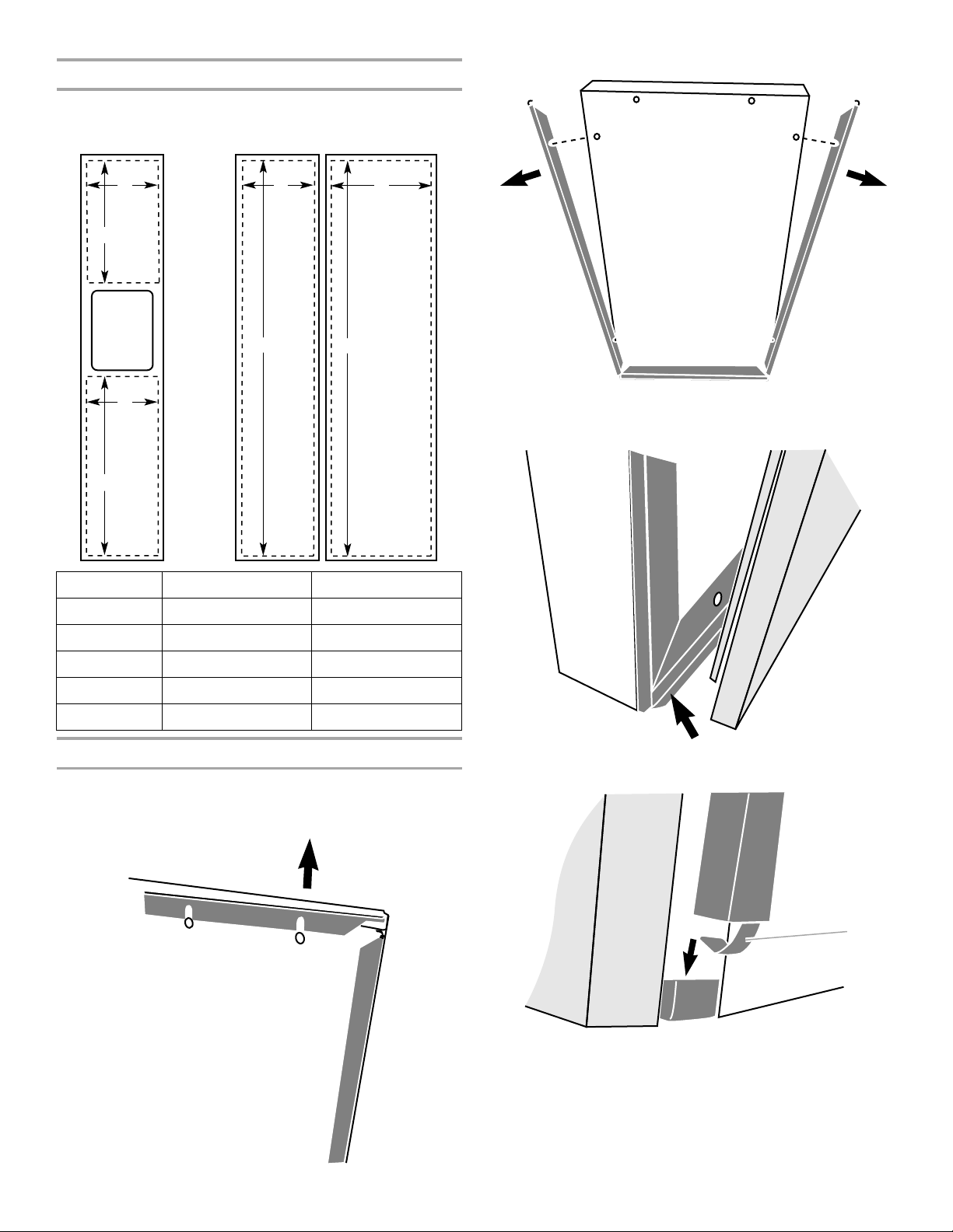
Backer and Spacer Panel Dimensions
E
A
B
C
D D
D
C
A
NOTE: The dashed lines represent the placement of the backer
and spacer panels on the decorative panels. Backer and spacer
panels should be centered vertically and horizontally.
2. Remove the side trim from each side of the freezer door.
3. Align the bottom edge of the door panel with the lower trim on
the bottom of the freezer door. Center the panel on the freezer
door.
Dimension Backer Panel Spacer Panel
A 19" (48.3 cm) 18³⁄₈" (46.7 cm)
B 31¹⁵⁄₃₂" (79.9 cm) 30³⁄₄" (78.1 cm)
C 67²⁹⁄₃₂" (172.5 cm) 66⁹⁄₁₆" (169.1 cm)
D 14⁷⁄₈" (37.8 cm) 14¹⁄₄" (36.2 cm)
E 19¹⁄₂" (49.6 cm) 18⁷⁄₈" (47.9 cm)
Install the Door Panels
NOTE: In the graphics throughout this section, dark gray
represents the door trim and light gray represents the door panel.
1. Remove the upper trim from the top of the freezer door.
4. Reseat each side trim, making sure the trim clip slides inside
the corner of the lower trim.
A. Trim clip
7
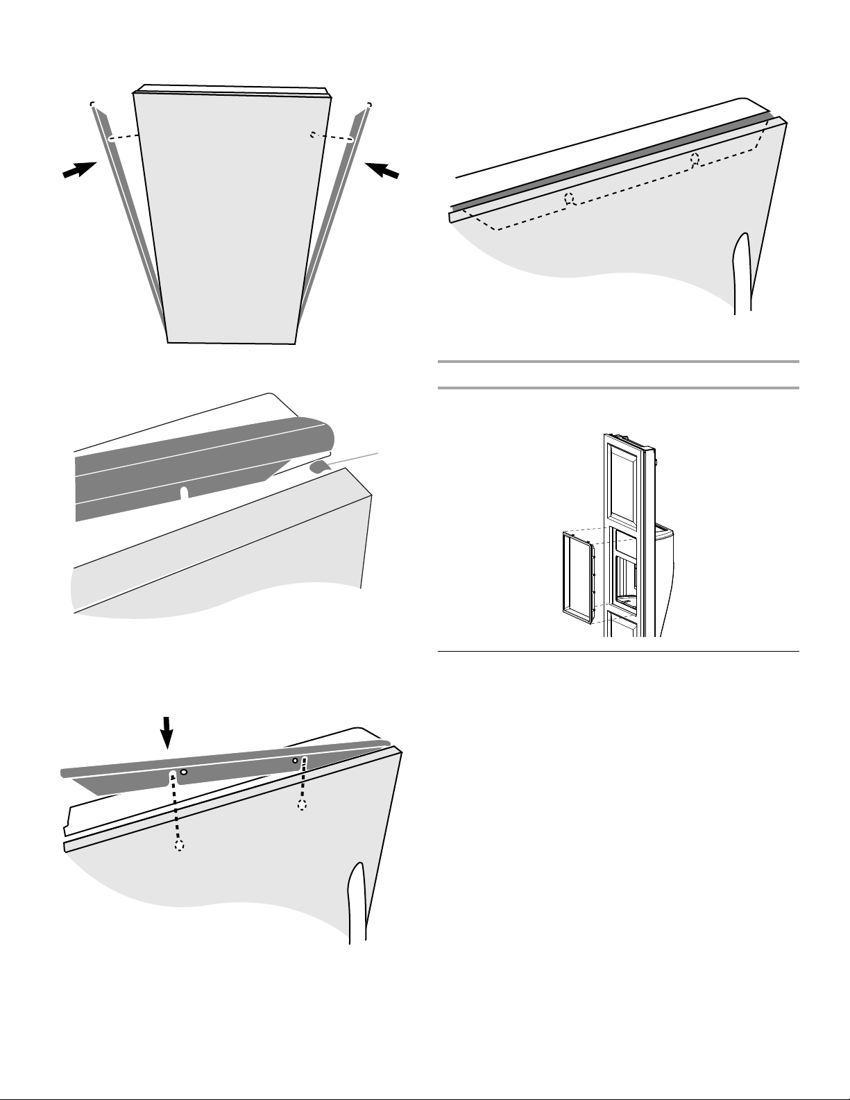
5. With the side trims properly seated in the lower trim, slide
A
each trim into the door panel groove.
6. Align the upper trim with the trim clips at the top of each side
trim.
8. When fully seated, the upper trim should be nearly flush with
the top of the freezer door, completely covering both side trim
clips.
9. Repeat the previous steps to install the refrigerator door
panel.
Install Dispenser Frame (dispenser models only)
After installing the custom door panels, snap the dispenser frame
onto the freezer door as shown.
A. Trim clip
7. Slide the upper trim into the door panel groove by applying
firm downward pressure. Be sure that the grooves on the
upper trim are properly aligned with the rivets on the door
panel.
Connect Water Supply
Read all directions before you begin.
IMPORTANT:
■ Plumbing shall be installed in accordance with the
International Plumbing Code and any local codes and
ordinances.
■ The gray water tubing on the back of the refrigerator (which is
used to connect to the household water line) is a PEX
(cross-linked polyethylene) tube. Copper and PEX tubing
connections from the household water line to the refrigerator
are acceptable, and will help avoid off-taste or odor in your ice
or water. Check for leaks.
If PEX tubing is used instead of copper, we recommend the
following Whirlpool Part Numbers:
W10505928RP (7 ft [2.14 m] jacketed PEX),
8212547RP (5 ft [1.52 m] PEX), or
W10267701RP (25 ft [7.62 m] PEX).
■ Install tubing only in areas where temperatures will remain
above freezing.
TOOLS NEEDED:
Gather the required tools and parts before starting installation.
■ Flat-blade screwdriver
■ ⁷⁄₁₆" and ¹⁄₂" open-end wrenches or two adjustable wrenches
■ ¹⁄₄" nut driver
8
Connect to Water Line
A
B
D
C
B CA
A
B
C
DEF
G
D
A B C
IMPORTANT: If you turn the refrigerator on before the water line is
connected, turn the ice maker OFF.
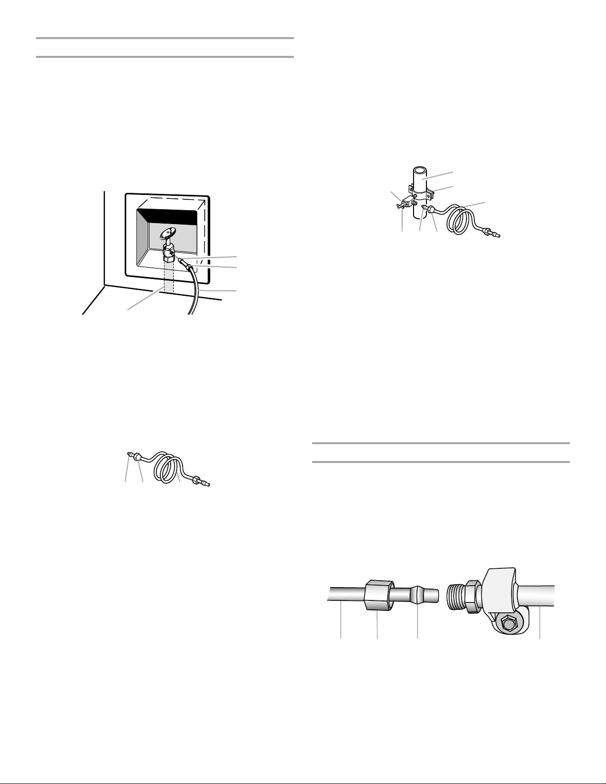
Style 1 (Recommended)
1. Unplug refrigerator or disconnect power.
2. Turn OFF main water supply. Turn ON nearest faucet long
enough to clear line of water.
3. Use a quarter-turn shutoff valve or the equivalent, served by a
¹⁄₂" copper household supply line.
NOTE: To allow sufficient water flow to the refrigerator, a
minimum ¹⁄₂" size copper household supply line is
recommended.
IMPORTANT:
■ Make sure it is a cold water pipe.
■ Horizontal pipe will work, but drill on the top side of the
pipe, not the bottom. This will help keep water away from
the drill and normal sediment from collecting in the valve.
4. Determine the length of copper tubing you need. Measure
from the connection on the lower rear corner of refrigerator to
the water pipe. Add 7 ft (2.1 m) to allow for cleaning. Use ¹⁄₄"
(6.35 mm) O.D. (outside diameter) copper tubing. Be sure both
ends of copper tubing are cut square.
5. Using a cordless drill, drill a ¹⁄₄" (6.35 mm) hole in the cold
water pipe you have selected.
A. Bulb
B. Nut
C. Copper tubing (to refrigerator)
D. Household supply line (½" minimum)
4. Now you are ready to connect the copper tubing to the shutoff
valve. Use ¹⁄₄" (6.35 mm) OD soft copper tubing to connect the
shutoff valve and the refrigerator.
■ Ensure that you have the proper length needed for the job.
Be sure both ends of the copper tubing are cut square.
■ Slip compression sleeve and compression nut onto
copper tubing as shown. Insert end of tubing into outlet
end squarely as far as it will go. Screw compression nut
onto outlet end with adjustable wrench. Do not
overtighten.
A. Compression sleeve
B. Compression nut
C. Copper tubing
5. Place the free end of the tubing into a container or sink, and
turn on main water supply to flush out tubing until water is
clear. Turn off shutoff valve on the water pipe.
NOTE: Always drain the water line before making the final
connection to the inlet of the water valve, to avoid possible
water valve malfunction.
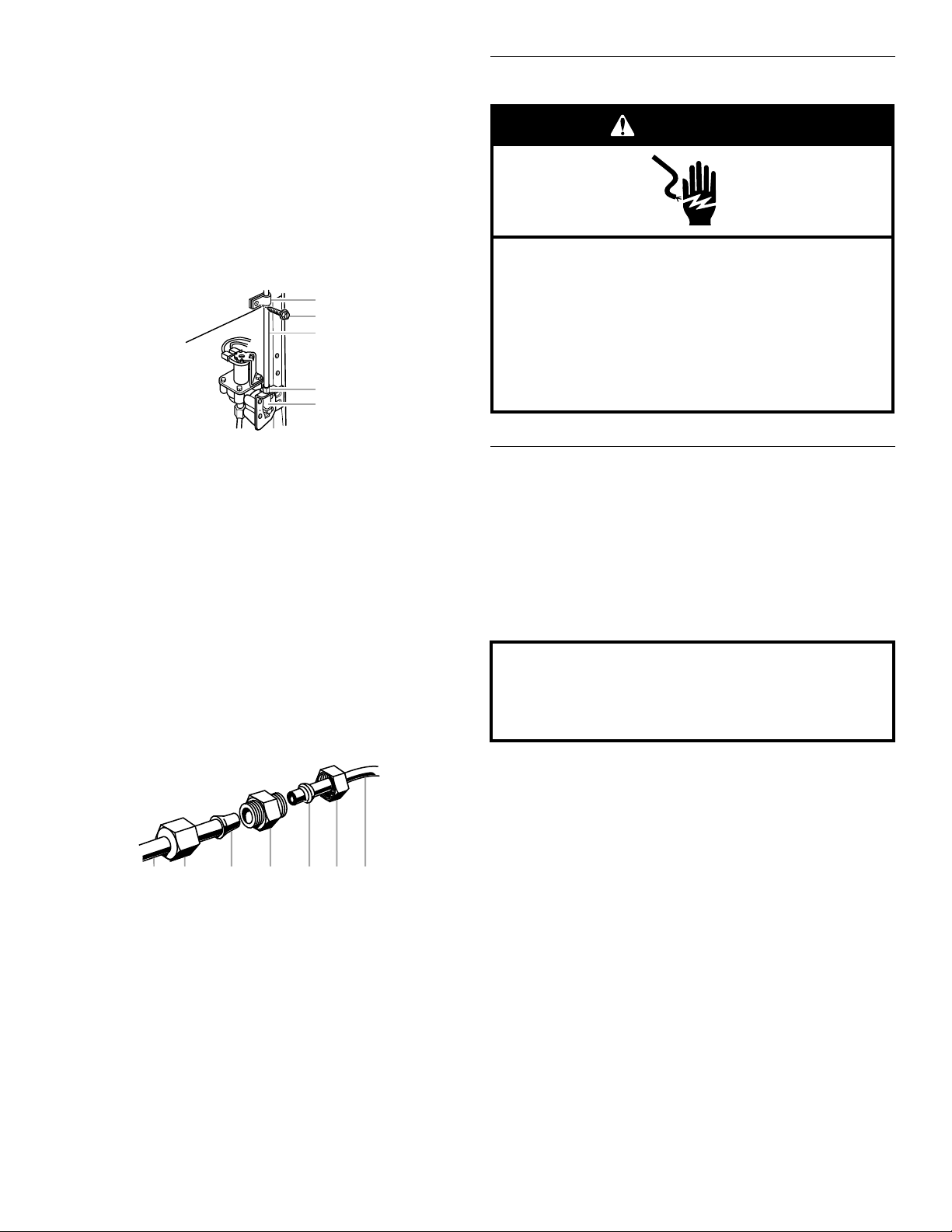
6. Bend the copper tubing to meet the water line inlet, which is
located on the back of the refrigerator cabinet as shown.
Leave a coil of copper tubing to allow the refrigerator to be
pulled out of the cabinet or away from the wall for service.
A. Cold water pipe
B. Pipe clamp
C. Copper tubing
D. Compression nut
E. Compression sleeve
F. Shutoff valve
G. Packing nut
6. Fasten the shutoff valve to the cold water pipe with the pipe
clamp. Be sure the outlet end is solidly in the ¹⁄₄" (6.35 mm)
drilled hole in the water pipe and that the washer is under the
pipe clamp. Tighten the packing nut. Tighten the pipe clamp
screws slowly and evenly so the washer makes a watertight
seal. Do not overtighten, or you may crush the copper tubing.
7. Slip the compression sleeve and compression nut on the
copper tubing as shown. Insert the end of the tubing into the
outlet end squarely as far as it will go. Screw the compression
nut onto outlet end with adjustable wrench. Do not
overtighten.
8. Place the free end of the tubing in a container or sink, and turn
ON the main water supply. Flush the tubing until water is clear.
Turn OFF the shutoff valve on the water pipe. Coil the copper
tubing.
Connect to Refrigerator
Style 1
1. Unplug refrigerator or disconnect power.
2. Remove and discard the short, black plastic part from the end
of the water line inlet.
3. Thread the nut onto the end of the tubing. Tighten the nut by
hand. Then tighten it with a wrench two more turns. Do not
overtighten.
NOTE: To avoid rattling, be sure the copper tubing does not
touch the cabinet’s side wall or other parts inside the cabinet.
Style 2
1. Unplug refrigerator or disconnect power.
2. Turn OFF main water supply. Turn ON nearest faucet long
enough to clear line of water.
3. Locate a
pipe near the refrigerator.
¹⁄₂" (1.27 cm) to 1¹⁄₄" (3.18 cm) vertical cold water
A. Household water line
B. Nut (purchased)
C. Ferrule (purchased)
D. Refrigerator water tubing
4. Install the water supply tube clamp around the water supply
line to reduce strain on the coupling.
5. Turn shutoff valve ON.
6. Check for leaks. Tighten any connections (including
connections at the valve) or nuts that leak.
9
Style 2
A
C
B
D
E
A B C D E F G
Electrical Shock Hazard
Plug into a grounded 3 prong outlet.
Do not remove ground prong.
Do not use an adapter.
Do not use an extension cord.
Failure to follow these instructions can result in death,
fire, or electrical shock.
WARNING
Do not use with water that is microbiologically unsafe or
of unknown quality without adequate disinfection before
or after the system. Systems certified for cyst reduction
may be used on disinfected waters that may contain
filterable cysts.
1. Unplug refrigerator or disconnect power.
2. Remove and discard the plastic part that is attached to the
inlet of the water valve.
3. Attach the copper tube to the valve inlet using a compression
nut and sleeve as shown. Tighten the compression nut. Do not
overtighten.
4. Use the tube clamp on the back of the refrigerator to secure
the tubing to the refrigerator as shown. This will help avoid
damage to the tubing when the refrigerator is pushed back
against the wall.
5. Turn shutoff valve ON.
6. Check for leaks. Tighten any connections (including
connections at the valve) or nuts that leak.
Plug in Refrigerator
A. Tube clamp
B. Tube clamp screw
C. Copper tubing
7. On some models, the ice maker is equipped with a built-in
water strainer. If your water conditions require a second water
strainer, install it in the ¹⁄₄" (6.35 mm) water line at either tube
connection. Obtain a water strainer from your nearest
appliance dealer.
D. Compression nut
E. Valve inlet
Style 3
1. Unplug refrigerator or disconnect power.
2. Remove and discard the black nylon plug from the gray water
tube on the rear of the refrigerator.
3. If the gray water tube supplied with the refrigerator is not long
enough, a ¹⁄₄" x ¹⁄₄" (6.35 mm x 6.35 mm) coupling is needed in
order to connect the water tubing to an existing household
water line. Thread the provided nut onto the coupling on the
end of the copper tubing.
NOTE: Tighten the nut by hand. Then tighten it with a wrench
two more turns. Do not overtighten.
A. Refrigerator water tubing
B. Nut (provided)
C. Bulb
D. Coupling (purchased)
4. Turn shutoff valve ON.
5. Check for leaks. Tighten any nuts or connections (including
connections at the valve) that leak.
E. Ferrule (purchased)
F. Nut (purchased)
G. Household water line
1. Plug into a grounded 3 prong outlet.
Prepare the Water System
Please read before using the water system.
Immediately after installation, follow the steps below to make sure
that the water system is properly cleaned.
1. Open the freezer door and turn off the ice maker. The On/Off
switch can only be accessed when the ice storage bin has
been removed. The switch is located on the freezer door, on
the left side of the wall that surrounds the ice storage bin.
Move the switch to the OFF (right) setting.
2. Make sure the water filter is properly installed.
3. Flush the water system. Use a sturdy container to depress
and hold the water dispenser lever for 5 seconds, then release
it for 5 seconds. Repeat until water begins to flow. Once water
begins to flow, continue depressing and releasing the
dispenser lever (5 seconds on, 5 seconds off) until a total of
3 gal. (12 L) has been dispensed. This will flush air from the
filter and water dispensing system, and prepare the water filter
for use. Additional flushing may be required in some
households. As air is cleared from the system, water may
spurt out of the dispenser.
4. Open the freezer door and turn on the ice maker. Move the
switch to the ON (left) position. See the Use & Care Guide or
User Instructions for further instructions on the operation of
your ice maker.
■ Allow 24 hours to produce the first batch of ice.
■ Discard the first three batches of ice produced.
■ Depending on your model, you may want to select the
maximum ice feature to increase the production of ice.
10
Leveling and Door Closing
A
B
C
Raise
Lower
A
Raise
Lower
Your refrigerator has two adjustable front feet — one on the right
and one on the left. In most cases, the refrigerator should be
steady when both feet are touching the floor. If your refrigerator
seems unsteady or if you want the doors to close more easily,
adjust the refrigerator's tilt using the instructions below:
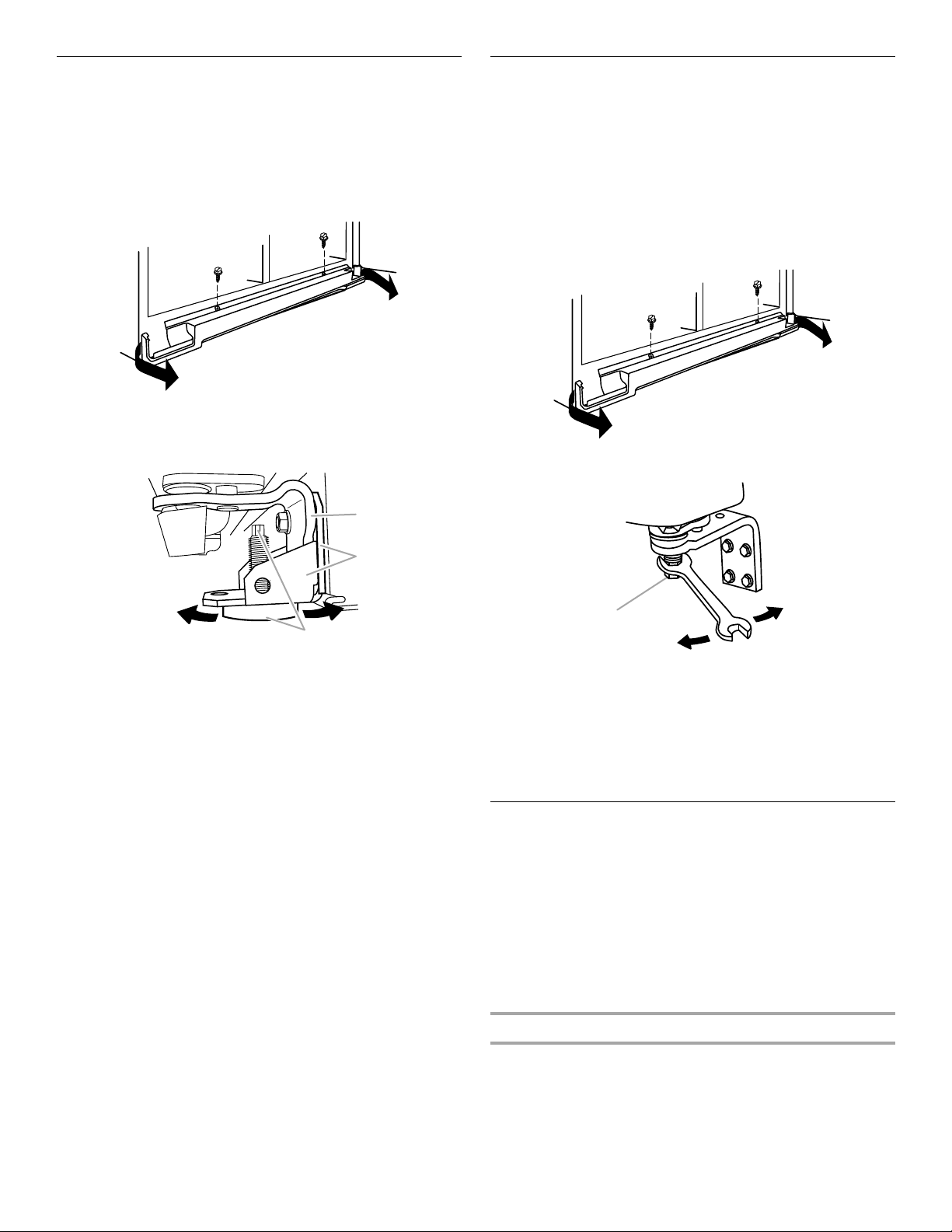
1. Move the refrigerator into its final location. Open both doors
to 90°. Remove the base grille by removing the two screws,
then pulling out on the outside corners.
NOTE: The doors must only be opened to 90°. If they are
opened all the way, the base grille will not come off.
2. The two leveling feet are located on the brackets on each side
of the product.
Door Alignment
A refrigerator that is not level from side-to-side may appear to
have doors that are not properly aligned. If the doors appear this
way, use the instructions in the previous section to check the
leveling.
The doors are designed to be slightly different heights when the
refrigerator is empty, in order to account for the weight of food
that will be placed on the doors. If the doors are still not aligned
after checking the leveling and loading the refrigerator with food,
follow the steps below to adjust the door alignment.
1. If necessary, open both doors to 90° and remove the base
grille.
2. Locate the alignment screw on the bottom hinge of the
refrigerator door.
A. Bottom hinge
B. Leveler bracket
C. Leveling foot
NOTE: Having someone push against the top of the refrigerator
takes some weight off the leveling feet. This makes it easier to
make adjustments.
3. Use a ¹⁄₄" open-ended or adjustable wrench to adjust the
leveling feet. Turn the leveling foot to the left to raise that side
of the product, or turn it to the right to lower that side of the
product.
4. Open both doors again and check that they close as easily as
you like. If not, tilt the refrigerator slightly more to the rear by
turning the leveling feet to the left. It may take several more
turns, and you should turn both leveling feet the same
amount.
NOTE: Whenever you need to move the refrigerator, turn the
leveling feet to the right until they are no longer touching the
ground. This will allow the refrigerator to roll more easily.
A. Alignment screw
3. Use a ⁵⁄₁₆" open-ended or adjustable wrench to turn the screw.
To raise the refrigerator door, turn the screw to the right. To
lower the door, turn the screw to the left.
4. Check that the doors are even at the top. If necessary,
continue to turn the alignment screw until the doors are
aligned.
5. Open both doors to 90°. Replace the base grille.
Complete Installation
1. Turn water supply line valve to “Open” position.
2. Turn refrigerator switch to ON position. Wait a few minutes.
Check water line connections for leaks.
3. Set refrigerator and freezer compartment controls to the
midpoint setting. Check that the compressor is operating
properly and that all lights are working.
4. Flush water system before using. See “Prepare the Water
System.”
NOTE: If construction will continue after refrigerator has been
installed, set controls to OFF.
If Refrigerator Does Not Operate
■ Check that the circuit breaker is not tripped or household fuse
blown.
■ Check that the power supply cord is plugged into a grounded
3prong outlet.
■ See “Problem Solver” or “Troubleshooting” in the Use & Care
Guide or User Instructions.
11
 Loading...