

Whirlpool WRS526SIAH00, WRS526SIAE00, WRS526SIAM00 User Instructions
THANK YOU for purchasing this high-quality product. If you should experience a problem not covered in TROUBLESHOOTING,
please visit our website at www.whirlpool.com for additional information. If you still need assistance, call us at 1-800-253-1301.
In Canada, visit our website at www.whirlpool.ca or call us at 1-800-807-6777.
You will need your model and serial number, located on the inside wall of the refrigerator compartment.
Para obtener acceso a "lnstrucciones para el usuario del refrigerador" en espa_ol, o para obtener informaci6n adicional acerca de
su producto, visite: www.whidpool.com.
Necesitara su nQmero de modelo y de serie, ubicado en el interior del compartimiento del refrigerador.
Tableof Contents/Tabledes matibres
REFRIGERATOR SAFETY ..................................................................... 1
INSTALLATION INSTRUCTIONS ......................................................... 2
REFRIGERATOR USE ......................................................................... 11
REFRIGERATOR CARE ....................................................................... 15
TROUBLESHOOTING .......................................................................... 16
ACCESSO RIES .................................................................................... 18
WATER FILTER CERTIFICATIONS .................................................... 18
PERFORMANCE DATA SHEET .......................................................... 19
WARRANTY .......................................................................................... 20
SI_CURITI_ DU RI_FRIGI_RATEUR ..................................................... 21
INSTRUCTIONS D'INSTALLATION ................................................... 22
UTILISATION DU RI=FRIGI=RATEUR ................................................. 31
ENTRETIEN DU RI_FRIGI_RATEUR ................................................... 36
DI_PANNAGE ........................................................................................ 37
ACCESSOIRES .................................................................................... 40
FEUlLLE DE DONNI=ES SUR LA PERFORMANCE .......................... 41
GARANTIE ............................................................................................ 42
REFRIGERATORSAFETY
Your safety and the safety of others are very important.
We have provided many important safety messages in this manual and on your appliance. Always read and obey all safety
messages.
This is the safety alert symbol.
This symbol alerts you to potential hazards that can kill or hurt you and others.
All safety messages will follow the safety alert symbol and either the word "DANGER" or "WARNING."
These words mean:
You can be killed or seriously injured if you don't immediately
follow instructions.
You can be killed or seriously injured if you don't follow
instructions.
All safety messages will tell you what the potential hazard is, tell you how to reduce the chance of injury, and tell you what can
happen if the instructions are not followed.
W10281961 C
IMPORTANT SAFETY INSTRUCTIONS
WARNING: To reduce the risk of fire, electric shock, or injury when using your refrigerator, follow these basic precautions:
• Plug into a grounded 3 prong outlet.
• Do not remove ground prong.
• Do not use an adapter.
• Do not use an extension cord.
• Disconnect power before servicing.
• Replace all parts and panels before operating.
• Remove doors from your old refrigerator.
SAVE THESE INSTRUCTIONS
• Use nonflammable cleaner.
• Keep flammable materials and vapors, such as gasoline,
away from refrigerator.
• Use two or more people to move and install refrigerator.
• Disconnect power before installing ice maker (on ice maker
kit ready models only).
• Use a sturdy glass when dispensing ice (on some models).
• Do not hit the refrigerator glass doors (on some models).
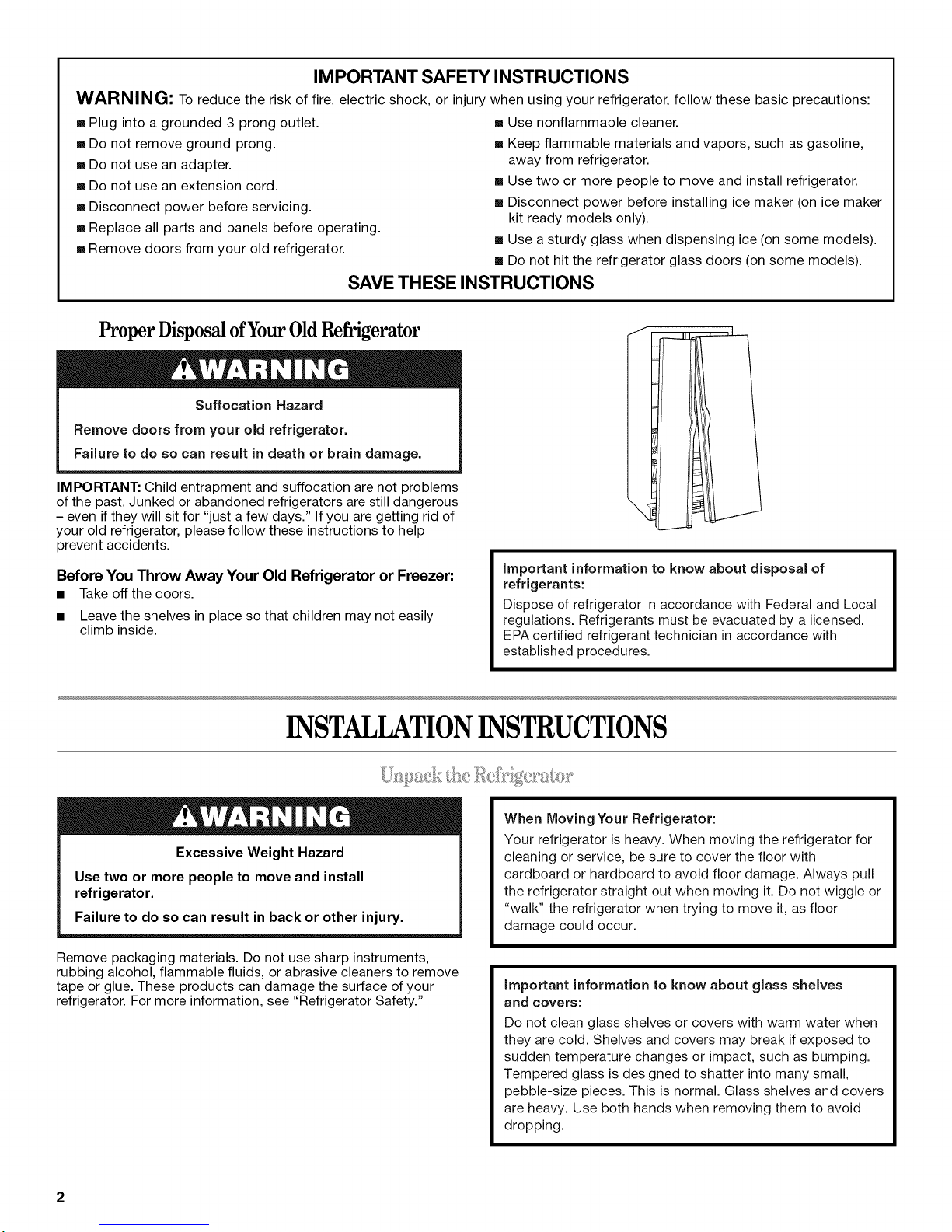
Proper Disposal of Your Old Refrigerator
Suffocation Hazard
Remove doors from your old refrigerator.
Failure to do so can result in death or brain damage.
IMPORTANT: Child entrapment and suffocation are not problems
of the past. Junked or abandoned refrigerators are still dangerous
- even if they will sit for "just a few days." If you are getting rid of
your old refrigerator, please follow these instructions to help
prevent accidents.
Before You Throw Away Your Old Refrigerator or Freezer:
• Takeoff the doors.
• Leave the shelves in place so that children may not easily
climb inside.
important information to know about disposal of
refrigerants:
Dispose of refrigerator in accordance with Federal and Local
regulations. Refrigerants must be evacuated by a licensed,
EPA certified refrigerant technician in accordance with
established procedures.
INSTALLATIONINSTRUCTIONS
Excessive Weight Hazard
Use two or more people to move and install
refrigerator.
Failure to do so can result in back or other injury.
Remove packaging materials. Do not use sharp instruments,
rubbing alcohol, flammable fluids, or abrasive cleaners to remove
tape or glue. These products can damage the surface of your
refrigerator. For more information, see "Refrigerator Safety."
When Moving Your Refrigerator:
Your refrigerator is heavy. When moving the refrigerator for
cleaning or service, be sure to cover the floor with
cardboard or hardboard to avoid floor damage. Always pull
the refrigerator straight out when moving it. Do not wiggle or
"walk" the refrigerator when trying to move it, as floor
damage could occur.
important information to know about glass shelves
and covers:
Do not clean glass shelves or covers with warm water when
they are cold. Shelves and covers may break if exposed to
sudden temperature changes or impact, such as bumping.
Tempered glass is designed to shatter into many small,
pebble-size pieces. This is normal. Glass shelves and covers
are heavy. Use both hands when removing them to avoid
dropping.
2
Gather the required tools and parts and read all instructions before starting installation. Save these instructions for future reference.
NOTE: Before moving your product into your home, measure the doorway of your home to see whether you need to remove the
refrigerator and freezer doors. If door removal is necessary, see the instructions below.
IMPORTANT: Before you begin, turn the refrigerator control OFR Unplug refrigerator or disconnect power.
TOOLS NEEDED:
Phillips screwdriver, ¾e" hex key, 1/4"hex-head socket wrench, 1/4"and 8/W' open-ended wrenches or adjustable wrench, internal star
drive or 3/8"hex-head socket wrench
Electrical Shock Hazard
Disconnect power before removing doors.
Failure to do so can result in death or electrical shock.
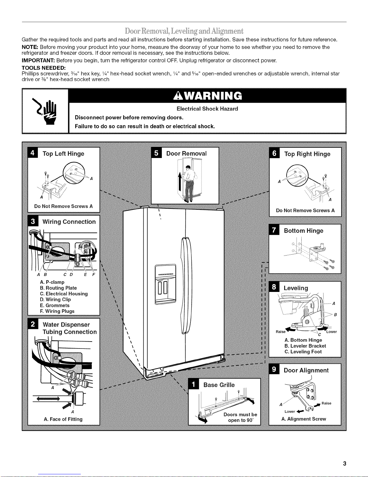
Top Left Hinge
Do Not Remove Screws A
Wiring Connection
/
A B C D E
A. P-clamp
B. Routing Plate
C. Electrical Housing
D. Wiring Clip
E. Grommets
F. Wiring Plugs
Water Dispenser
Tubing Connection
Door Removal
Top Right Hinge
Do Not Remove Screws A
Bottom Hinge
(2
Leveling
A. Bottom Hinge
B. Leveler Bracket
C. Leveling Foot
A
A
A. Face of Fitting
Door Alignment
Base Grille
A _'__JB' Raise
__ust be
A.Alignment Screw
Remove the Doors
Electrical Shock Hazard
Disconnect power before removing doors.
Failure to do so can result in death or electrical shock.
1.
Unplug refrigerator or disconnect power.
2.
Open both doors to 90 °. Remove the base grille by removing
the two screws, then pulling out on the outside corners. See
Graphic 1.
NOTE: The doors must only be opened to 90°. If they are
opened all the way, the base grille will not come off.
3.
Remove food, the ice storage bin, and any adjustable door or
utility bins from doors.
4.
Disconnect the water tubing, located behind the base grille on
the freezer door side. The dispenser tubing runs through the
door hinge, and must be disconnected in order to remove the
door. See Graphic 2.
• Press the colored outer ring against the face of fitting and
pull the water tubing free.
NOTE: Keep the water tubing connector attached to the
tube that runs underneath the freezer. The door cannot be
removed if the connector is still attached to the tube that
runs through the door hinge.
5.
Disconnect the wiring, located behind the base grille on the
freezer door side. See Graphic 3.
• Remove the P-clamp using a 1/4"hex-head socket wrench.
Remove the small wiring bundle from the P-clamp.
Remove the wiring clip using a 1/4"hex-head socket
wrench.
Pull the electrical housing out from under the refrigerator.
Disconnect the wiring plugs from the housing.
Gently pull the large wiring bundle (with two white plugs)
through the routing plate.
6.
Close both doors and keep them closed until you are ready to
lift them free from the cabinet.
7.
Use a ¾e" hex key to remove the top left hinge screws as
shown. See Graphic 4.
IMPORTANT: Do not remove either screw A.
Excessive Weight Hazard
Use two or more people to lift the freezer door.
Failure to do so can result in back or other injury.
8. Lift freezer door straight up off bottom hinge. See Graphic 5.
The water tubing and wiring remain attached to the freezer
door and pull through the bottom left hinge.
NOTE: This may require two people - one to lift the door and
another to feed the water tubing and wiring through the hinge.
Be sure the hole in the hinge is clear of obstructions, then
gently pull one water tube through the hinge. (Avoid kinking
the tube.) Next, gently pull the other water tube through the
hinge, again avoiding kinks. Finally, gently pull the wiring
bundle (including the grommet and wiring plugs) through the
hinge.
IMPORTANT: Rest the door on its side on a soft, clean
surface, such as a towel, blanket or piece of cardboard. This
will help avoid damaging the door, water tubing and wiring.
g.
Use a ¾e" hex key to remove the top right hinge screws as
shown. See Graphic 6.
IMPORTANT: Do not remove either screw A.
10. Lift the refrigerator door straight up off bottom hinge.
11. It may not be necessary to remove the bottom hinges to move
the refrigerator through a doorway. Both bottom hinges have
similar construction.
• If necessary, use an internal star drive or a 3/8"hex-head
socket wrench to remove the bottom hinges. See
Graphic 7.
IMPORTANT: The leveler brackets are mounted behind
the hinges. If you remove the hinges, make sure that the
leveler brackets are replaced when reinstalling the hinges.
Replace the Doors and Hinges
1. Replace both bottom hinges, if removed. Make sure that the
leveler brackets are assembled behind the hinges. Tighten
screws.
IMPORTANT: When the screws are tightened properly, there
should not be any gaps between the refrigerator, leveler
bracket and hinge.
NOTE: There are two wiring bundles that run underneath the
freezer - a large bundle with a large grommet and two white plugs
at the end, and asmall bundle with a small grommet and one
yellow plug at the end.
Excessive Weight Hazard
Use two or more people to lift the freezer door.
Failure to do so can result in back or other injury.
2.
Before replacing the freezer door on the bottom left hinge,
feed the small wiring bundle through the hinge. Assistance
may be needed.
IMPORTANT: Do not feed the large wiring bundle through the
hinge. This bundle is intended to run directly from the door to
the connections beneath the freezer. Forcing the large bundle
through the hinge may damage the door and/or the wiring,
and will keep the door from closing properly.
3. Feed both water tubes through the bottom left hinge, then
replace the freezer door on the hinge. Assistance may be
needed.
NOTE: Provide additional support for the doors while the top
hinges are being replaced. Do not depend on the door magnets to
hold the doors in place while you are working.
4. Align and replace the top left hinge as shown. See Graphic 4.
Tighten screws.
5. Reconnectwatertubingandwiring.
IMPORTANT:Donotintertwinethewatertubingandwiring
bundleswhenreconnectingthem.
Pushthelarger5/le"(7.94mm)watertubeintotheblue
fittinguntilitstops,thenpushthesmaller1/4"(6.35mm)
watertubeintothegreenfittinguntilitstops.See
Graphic2.
• ReinstalltheP-clamparoundthesmallwiringbundle(with
oneyellowplug),thenreplacetheP-clamponthetop
screwholeoftheroutingplate.SeeGraphic3.
Gentlyroutethelargewiringbundle(withtwowhiteplugs)
throughtheholeintheroutingplate,sothatthewiring
runsbehindtherightsideoftheroutingplate.See
Graphic3.
NOTE:Thelargewiringbundleshouldalwaysremain
belowthesmallwiringbundle.
Reconnectthewiringplugstotheelectricalhousing,then
pushthehousingbackundertherefrigerator.Aligntheleft
holeinthefrontlipofthehousingwiththerightholeinthe
refrigerator'sbasecrossbar.SeeGraphic3.
Reinstallthewiringclipoverthegrommets.Firstinstallthe
smallergrommetintothetopoftheclip,theninstallthe
largergrommetintothebottomoftheclip(closesttothe
screwhole).SeeGraphic3.
Aligntheclip'sscrewholewiththeleftholeintheelectrical
housingandtherightholeinthecrossbar,andscrewin
theclipusingasinglescrew.Tightenscrew.See
Graphic3.
IMPORTANT:Onceconnected,thewiringbundlesshould
notbetaut.Someflexibilityisneededtoallowthefreezer
doortoopenproperly.
6. Replacetherefrigeratordoorbyliftingthedoorontothe
bottomrighthinge.
7. Alignandreplacethetoprighthingeasshown.SeeGraphic6.
Tightenscrews.
8. Replacetheicestoragebinandanyadjustabledoororutility
bins.
9. Plugrefrigeratorintoagrounded3prongoutlet.
Leveling and Door Closing
Your refrigerator has two adjustable front feet -- one on the right
and one on the left. In most cases, the refrigerator should be
steady when both feet are touching the floor. If your refrigerator
seems unsteady or if you want the doors to close more easily,
adjust the refrigerator's tilt using the instructions below:
1. Move the refrigerator into its final location. If necessary, open
both doors to 90° and remove the base grille. See Graphic 1.
2. The two leveling feet are located on the brackets on each side
of the product. See Graphic 8.
NOTE: Having someone push against the top of the refrigerator
takes some weight off the leveling feet. This makes it easier to
make adjustments.
3. Use a 1/4"open-ended or adjustable wrench to adjust the
leveling feet. Turn the leveling foot to the left to raise that side
of the product, or turn it to the right to lower that side of the
product.
4. Open both doors again and check that they close as easily as
you like. If not, tilt the refrigerator slightly more to the rear by
turning the leveling feet to the left. It may take several more
turns, and you should turn both leveling feet the same
amount.
NOTE: Whenever you need to move the refrigerator, turn the
leveling feet to the right until they are no longer touching the
ground. This will allow the refrigerator to roll more easily.
Door Alignment
A refrigerator that is not level from side-to-side may appear to
have doors that are not properly aligned. If the doors appear this
way, use the instructions in the previous section to check the
leveling.
The doors are designed to be slightly different heights when the
refrigerator is empty, in order to account for the weight of food
that will be placed on the doors. If the doors are still not aligned
after checking the leveling and loading the refrigerator with food,
follow the steps below to adjust the door alignment.
1. If necessary, open both doors to 90° and remove the base
grille. See Graphic 1.
2. Locate the alignment screw on the bottom hinge of the
refrigerator door. See Graphic 9.
3. Use a5/le"open-ended or adjustable wrench to turn the screw.
To raise the refrigerator door, turn the screw to the right. To
lower the door, turn the screw to the left.
4. Check that the doors are even at the top. If necessary,
continue to turn the alignment screw until the doors are
aligned.
5. Open both doors to 90 °. Replace the base grille. See
Graphic 1.
Style I - Setscrews
PARTS INCLUDED: Door handles (2), 1/8"hex key, spare
setscrew(s)
To Install the Handles:
NOTE: The handle mounting setscrews are preinstalled in the
handle.
1. Remove the handles, which are packed inside the refrigerator.
NOTE: To avoid scratching the finish, place the handles on a
towel or other soft surface.
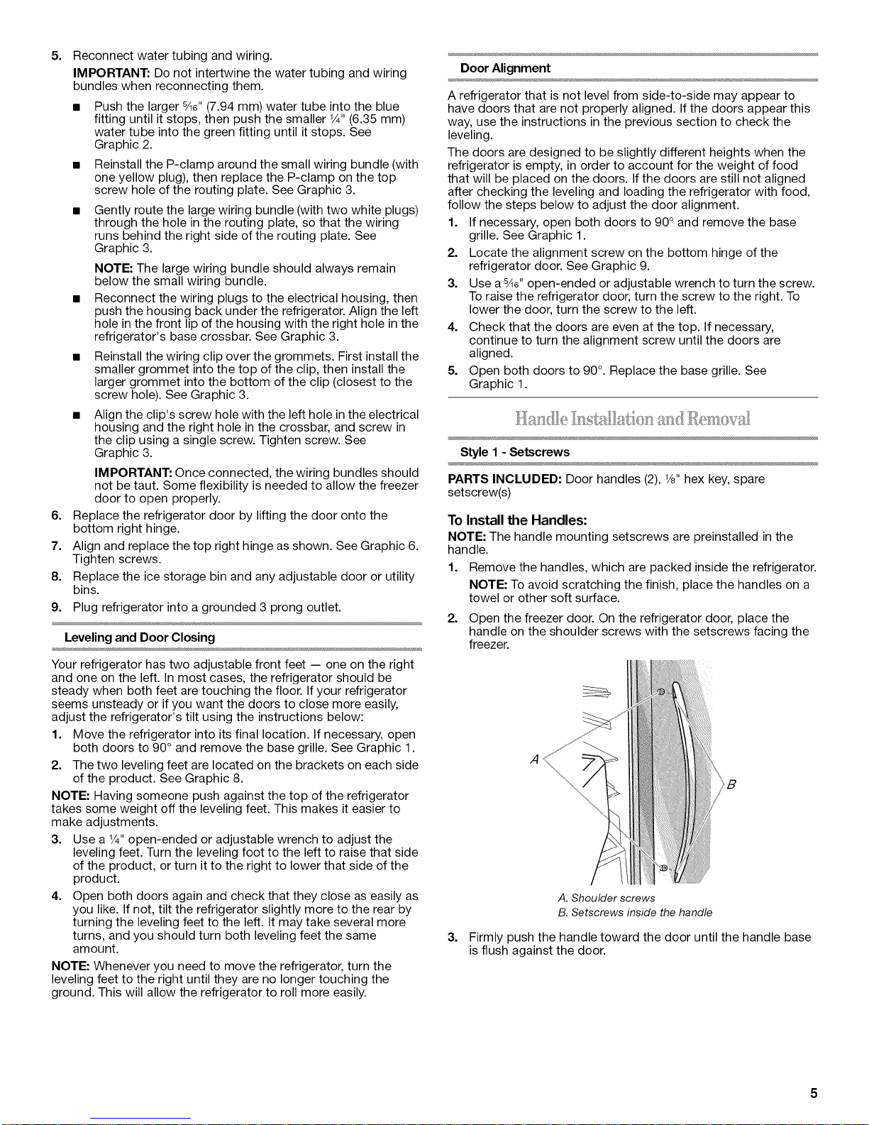
2. Open the freezer door. On the refrigerator door, place the
handle on the shoulder screws with the setscrews facing the
freezer.
.4
_B
A. Shoulder screws
B. Setscrews inside the handle
3.
Firmly push the handle toward the door until the handle base
is flush against the door.
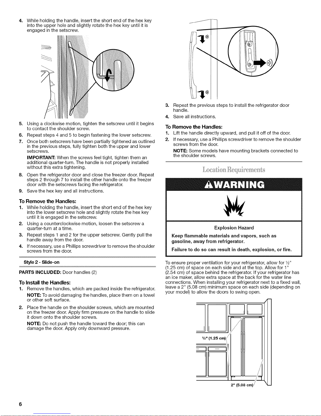
4,
While holding the handle, insert the short end of the hex key
into the upper hole and slightly rotate the hex key until it is
engaged inthe setscrew.
5,
Using a clockwise motion, tighten the setscrew until it begins
to contact the shoulder screw.
6.
Repeat steps 4 and 5 to begin fastening the lower setscrew.
7.
Once both setscrews have been partially tightened as outlined
in the previous steps, fully tighten both the upper and lower
setscrews.
IMPORTANT: When the screws feel tight, tighten them an
additional quarter-turn. The handle is not properly installed
without this extra tightening.
8. Open the refrigerator door and close the freezer door. Repeat
steps 2 through 7 to install the other handle onto the freezer
door with the setscrews facing the refrigerator.
9. Save the hex key and all instructions.
3.
Repeat the previous steps to install the refrigerator door
handle.
4.
Save all instructions.
To Remove the Handles:
1. Lift the handle directly upward, and pull it off of the door.
2. If necessary, use a Phillips screwdriver to remove the shoulder
screws from the door.
NOTE: Some models have mounting brackets connected to
the shoulder screws.
To Remove the Handles:
1. While holding the handle, insert the short end of the hex key
into the lower setscrew hole and slightly rotate the hex key
until it is engaged in the setscrew.
2. Using a counterclockwise motion, loosen the setscrew a
quarter-turn at a time.
3. Repeat steps 1 and 2 for the upper setscrew. Gently pull the
handle away from the door.
4. If necessary, use a Phillips screwdriver to remove the shoulder
screws from the door.
Style 2 - Slide-on
PARTS INCLUDED: Door handles (2)
To Install the Handles:
1. Remove the handles, which are packed inside the refrigerator.
NOTE: To avoid damaging the handles, place them on a towel
or other soft surface.
2.
Place the handle on the shoulder screws, which are mounted
on the freezer door. Apply firm pressure on the handle to slide
it down onto the shoulder screws.
NOTE: Do not push the handle toward the door; this can
damage the door. Apply only downward pressure.
Explosion Hazard
Keep flammable materials and vapors, such as
gasoline, away from refrigerator.
Failure to do so can result in death, explosion, or fire.
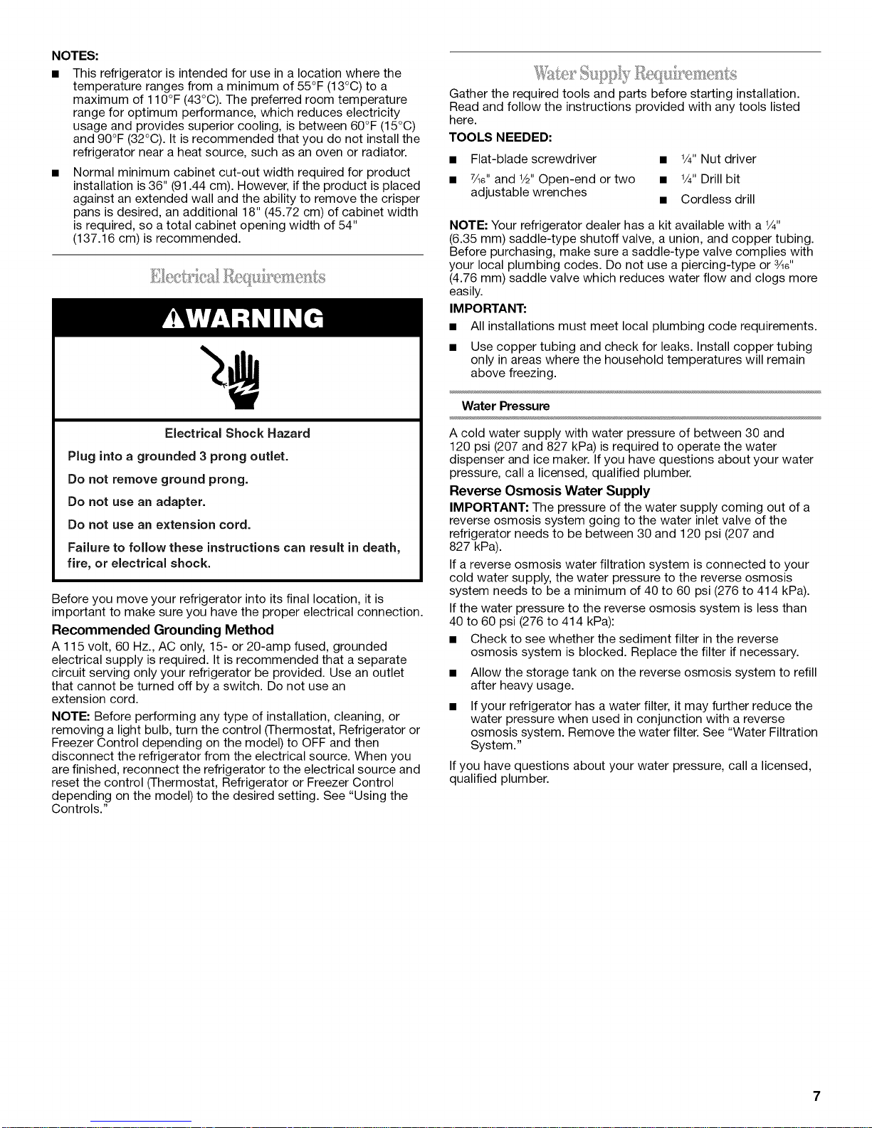
To ensure proper ventilation for your refrigerator, allow for 1/2"
(1.25 cm) of space on each side and at the top. Allow for 1"
(2.54 cm) of space behind the refrigerator. If your refrigerator has
an ice maker, allow extra space at the back for the water line
connections. When installing your refrigerator next to a fixed wall,
leave a 2" (5.08 cm) minimum space on each side (depending on
your model) to allow the doors to swing open.
I ,11,I
:=....- ..........=
/
1/2"(1.25 cm)
- II -- I
6
'11'I
/
2" (5.08cm)/
NOTES:
This refrigerator is intended for use in a location where the
temperature ranges from a minimum of 55°F (13°C) to a
maximum of 110°F (43°C). The preferred room temperature
range for optimum performance, which reduces electricity
usage and provides superior cooling, is between 60°F (15°C)
and 90°F (32°C). It is recommended that you do not install the
refrigerator near a heat source, such as an oven or radiator.
Normal minimum cabinet cut-out width required for product
installation is 36" (91.44 cm). However, if the product is placed
against an extended wall and the ability to remove the crisper
pans is desired, an additional 18" (45.72 cm) of cabinet width
is required, so a total cabinet opening width of 54"
(137.16 cm)is recommended.
Gather the required tools and parts before starting installation.
Read and follow the instructions provided with any tools listed
here.
TOOLS NEEDED:
• Flat-blade screwdriver • 1/4"Nut driver
• 7/le"and 1/2"Open-end or two • 1/4"Drill bit
adjustable wrenches • Cordless drill
NOTE: Your refrigerator dealer has a kit available with a 1/4"
(6.35 mm) saddle-type shutoff valve, a union, and copper tubing.
Before purchasing, make sure a saddle-type valve complies with
your local plumbing codes. Do not use a piercing-type or ¾e"
(4.76 mm) saddle valve which reduces water flow and clogs more
easily.
IMPORTANT:
• All installations must meet local plumbing code requirements.
• Use copper tubing and check for leaks. Install copper tubing
only in areas where the household temperatures will remain
above freezing.
Water Pressure
Electrical Shock Hazard
Plug into a grounded 3 prong outlet.
Do not remove ground prong.
Do not use an adapter.
Do not use an extension cord.
Failure to follow these instructions can result in death,
fire, or electrical shock.
Before you move your refrigerator into its final location, it is
important to make sure you have the proper electrical connection.
Recommended Grounding Method
A 115 volt, 60 Hz., AC only, 15- or 20-amp fused, grounded
electrical supply is required. It is recommended that a separate
circuit serving only your refrigerator be provided. Use an outlet
that cannot be turned off by a switch. Do not use an
extension cord.
NOTE: Before performing any type of installation, cleaning, or
removing a light bulb, turn the control (Thermostat, Refrigerator or
Freezer Control depending on the model) to OFF and then
disconnect the refrigerator from the electrical source. When you
are finished, reconnect the refrigerator to the electrical source and
reset the control (Thermostat, Refrigerator or Freezer Control
depending on the model) to the desired setting. See "Using the
Controls."
A cold water supply with water pressure of between 30 and
120 psi (207 and 827 kPa) is required to operate the water
dispenser and ice maker. Ifyou have questions about your water
pressure, call a licensed, qualified plumber.
Reverse Osmosis Water Supply
IMPORTANT: The pressure of the water supply coming out of a
reverse osmosis system going to the water inlet valve of the
refrigerator needs to be between 30 and 120 psi (207 and
827 kPa).
If a reverse osmosis water filtration system is connected to your
cold water supply, the water pressure to the reverse osmosis
system needs to be a minimum of 40 to 60 psi (276 to 414 kPa).
If the water pressure to the reverse osmosis system is less than
40 to 60 psi (276 to 414 kPa):
• Check to see whether the sediment filter in the reverse
osmosis system is blocked. Replace the filter if necessary.
• Allow the storage tank on the reverse osmosis system to refill
after heavy usage.
If your refrigerator has a water filter, it may further reduce the
water pressure when used in conjunction with a reverse
osmosis system. Remove the water filter. See "Water Filtration
System."
If you have questions about your water pressure, call a licensed,
qualified plumber.
_O_d _-_ _....
Readalldirectionsbeforeyoubegin.
IMPORTANT:
• Plumbingshallbeinstalledinaccordancewiththe
InternationalPlumbingCodeandanylocalcodesand
ordinances.
• UsecoppertubingorWhirlpoolsupplyline,PartNumber
8212547RP,andcheckforleaks.
• Installtubingonlyinareaswheretemperatureswillremain
abovefreezing.
TOOLSNEEDED:
Gathertherequiredtoolsandpartsbeforestartinginstallation.
• Flat-bladescrewdriver
• 7/le"andV2" open-end wrenches or two adjustable wrenches
• V4"nut driver
Connect to Water Line
IMPORTANT: Ifyou turn the refrigerator on before the water line is
connected, turn the ice maker OFE
1. Unplug refrigerator or disconnect power.
2. Turn OFF main water supply. Turn ON nearest faucet long
enough to clear line of water.
3. Use a quarter-turn shutoff valve or the equivalent, served by a
V2"copper household supply line.
NOTE: To allow sufficient water flow to the refrigerator, a
minimum V2" size copper household supply line is
recommended.
5.
Place the free end of the tubing into a container or sink, and
turn on main water supply to flush out tubing until water is
clear. Turn off shutoff valve on the water pipe.
NOTE: Always drain the water line before making the final
connection to the inlet of the water valve, to avoid possible
water valve malfunction.
6.
Bend the copper tubing to meet the water line inlet, which is
located on the back of the refrigerator cabinet as shown.
Leave a coil of copper tubing to allow the refrigerator to be
pulled out of the cabinet or away from the wall for service.
Connect to Refrigerator
Style 1
1. Unplug refrigerator or disconnect power.
2. Remove and discard the short, black plastic part from the end
of the water line inlet.
3.
Thread the nut onto the end of the tubing. Tighten the nut by
hand. Then tighten it with a wrench two more turns. Do not
overtighten.
NOTE: To avoid rattling, be sure the copper tubing does not
touch the cabinet's side wall or other parts inside the cabinet.
A B C D
ilia
D
A. Bulb
B. Nut
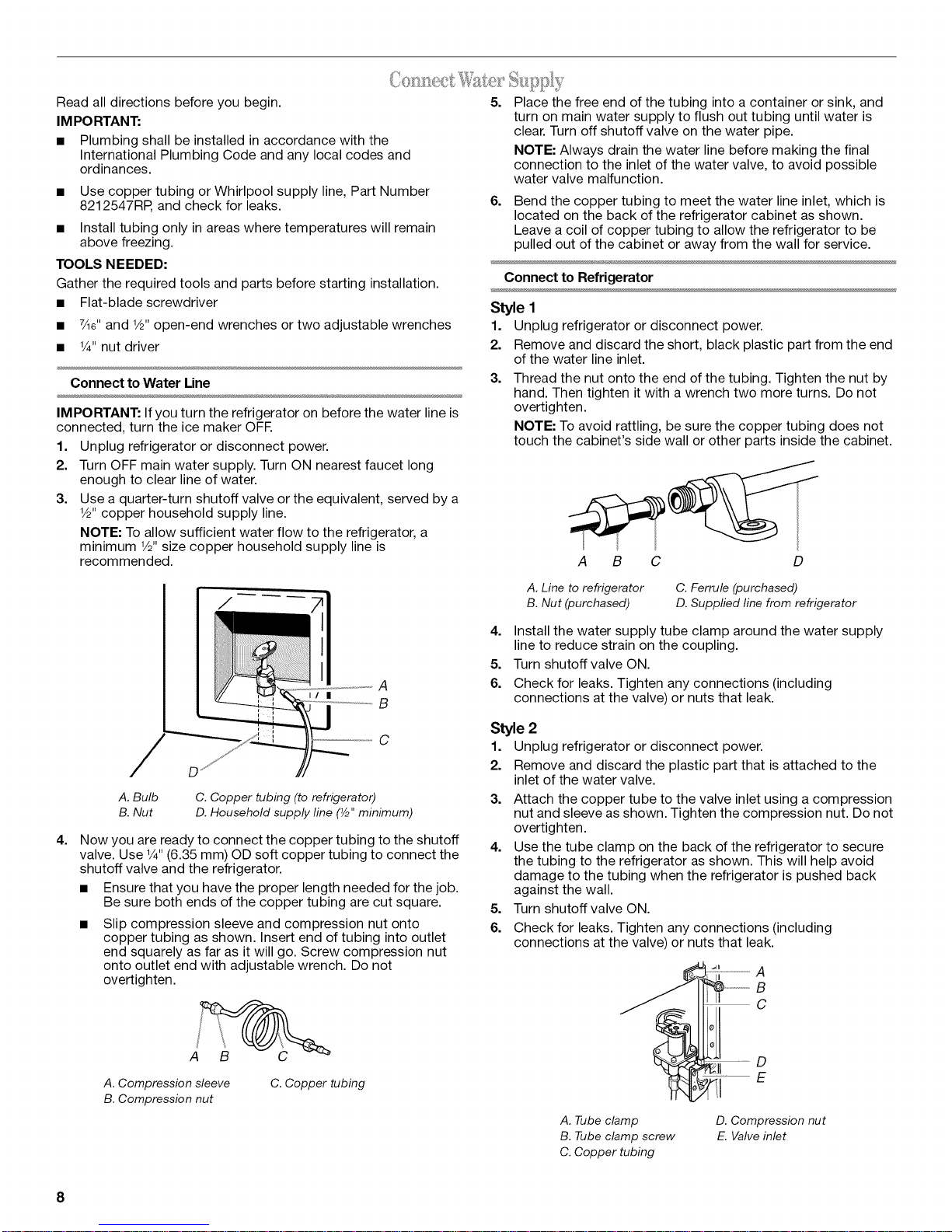
4=
Now you are ready to connect the copper tubing to the shutoff
valve. Use V4"(6.35 mm) OD soft copper tubing to connect the
shutoff valve and the refrigerator.
• Ensure that you have the proper length needed for the job.
Be sure both ends of the copper tubing are cut square.
Slip compression sleeve and compression nut onto
copper tubing as shown. Insert end of tubing into outlet
end squarely as far as it will go. Screw compression nut
onto outlet end with adjustable wrench. Do not
overtighten.
C. Copper tubing (to refrigerator)
D. Household supply line (Y2"minimum)
A
B
C
A. Line to refrigerator
B. Nut (purchased)
4=
Install the water supply tube clamp around the water supply
line to reduce strain on the coupling.
5.
Turn shutoff valve ON.
6.
Check for leaks. Tighten any connections (including
connections at the valve) or nuts that leak.
Style 2
1. Unplug refrigerator or disconnect power.
2. Remove and discard the plastic part that is attached to the
inlet of the water valve.
3.
Attach the copper tube to the valve inlet using a compression
nut and sleeve as shown. Tighten the compression nut. Do not
overtighten.
4=
Use the tube clamp on the back of the refrigerator to secure
the tubing to the refrigerator as shown. This will help avoid
damage to the tubing when the refrigerator is pushed back
against the wall.
5.
Turn shutoff valve ON.
6.
Check for leaks. Tighten any connections (including
connections at the valve) or nuts that leak.
C. Ferrule (purchased)
D. Supplied line from refrigerator
__14! .....................ABc
A. Compression sleeve
B. Compression nut
C. Copper tubing
8
A. Tube clamp
B. Tube clamp screw
C. Copper tubing
E
D. Compression nut
E. Valve inlet
7.
On some models, the ice maker is equipped with a built-in
water strainer. If your water conditions require a second water
strainer, install it in the 1/4"(6.35 mm) water line at either tube
connection. Obtain a water strainer from your nearest
appliance dealer.
Style 3
1. Unplug refrigerator or disconnect power.
2. Remove and discard the black nylon plug from the gray water
tube on the rear of the refrigerator.
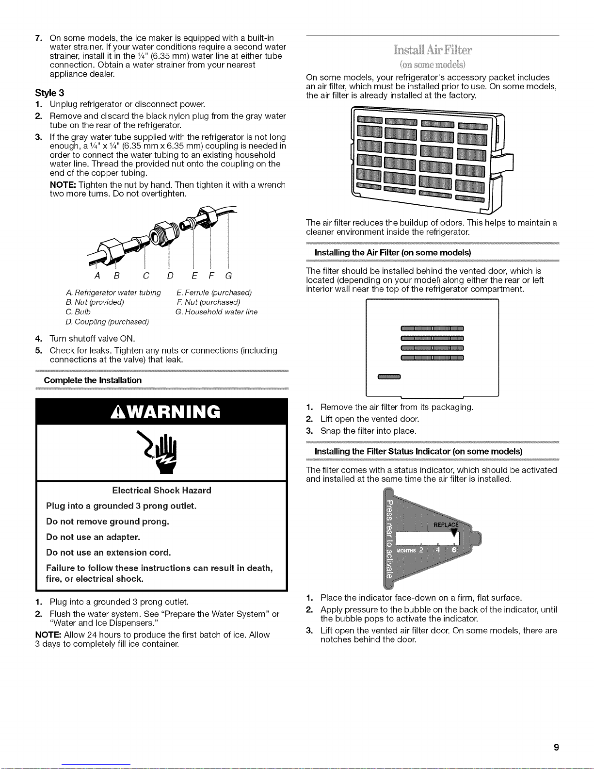
3. If the gray water tube supplied with the refrigerator is not long
enough, aV4"x 1/4"(6.35 mm x 6.35 mm) coupling is needed in
order to connect the water tubing to an existing household
water line. Thread the provided nut onto the coupling on the
end of the copper tubing.
NOTE: Tighten the nut by hand. Then tighten it with a wrench
two more turns. Do not overtighten.
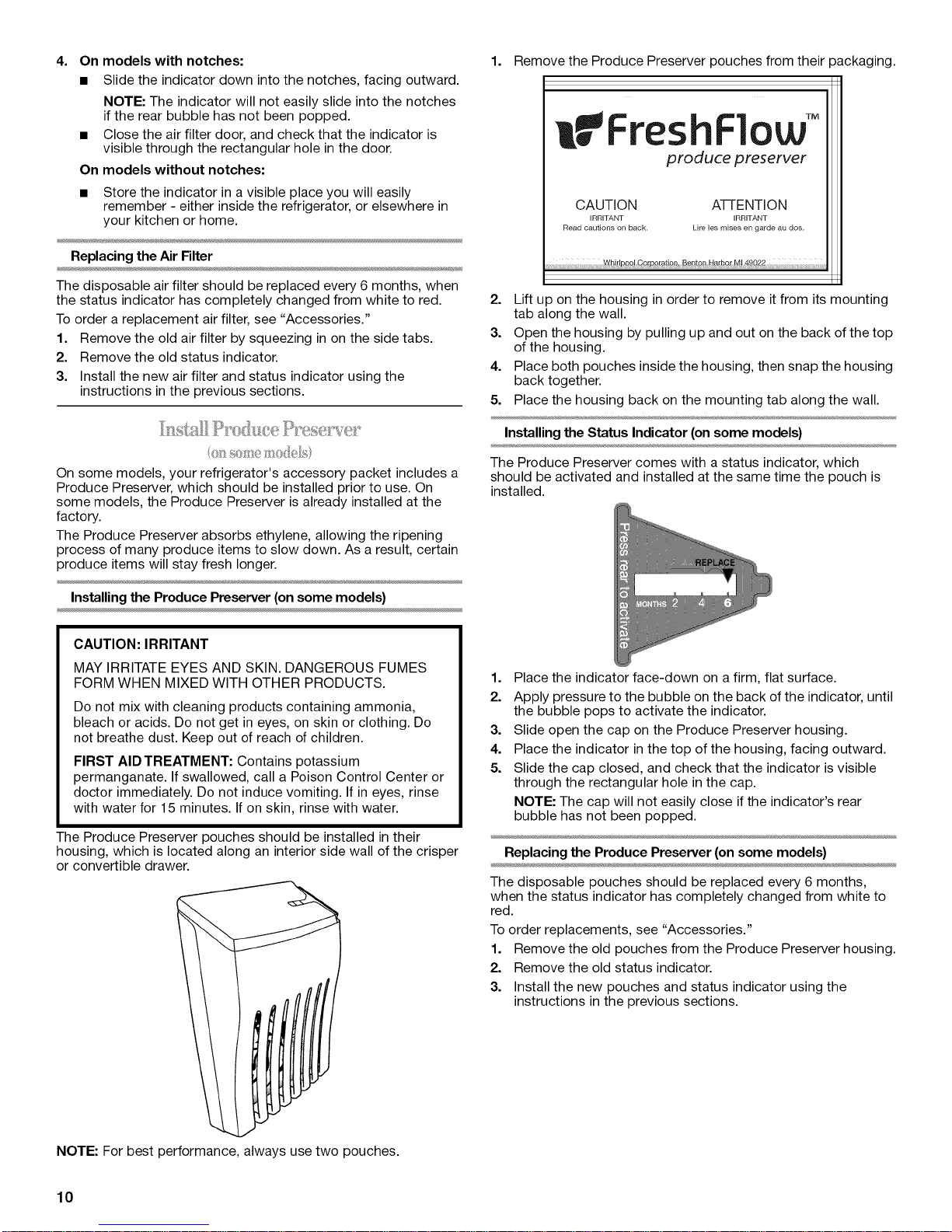
On some models, your refrigerator's accessory packet includes
an air filter, which must be installed prior to use. On some models,
the air filter is already installed at the factory.
The air filter reduces the buildup of odors. This helps to maintain a
cleaner environment inside the refrigerator.
Installing the Air Filter (on some models)
A B C D E F G
A. Refrigerator water tubing
B. Nut (provided)
C. Bulb
D. Coupfing (purchased)
E. Ferrule (purchased)
F Nut (purchased)
G. Household water line
4. Turn shutoff valve ON.
5. Check for leaks. Tighten any nuts or connections (including
connections at the valve) that leak.
Complete the Installation
Electrical Shock Hazard
Plug into a grounded 3 prong outlet.
Do not remove ground prong.
Do not use an adapter.
Do not use an extension cord.
Failure to follow these instructions can result in death,
fire, or electrical shock.
The filter should be installed behind the vented door, which is
located (depending on your model) along either the rear or left
interior wall near the top of the refrigerator compartment.
m._ im
1. Remove the air filter from its packaging.
2. Lift open the vented door.
3. Snap the filter into place.
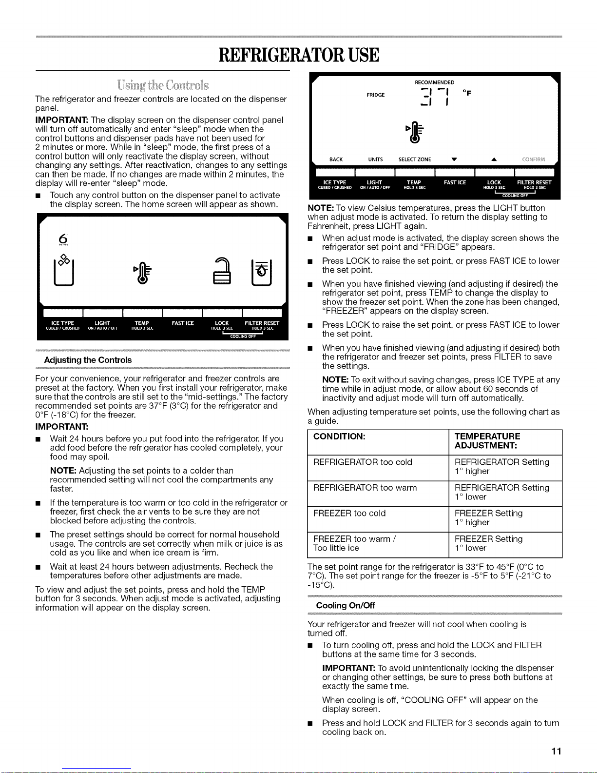
Installing the Filter Status Indicator (on some models)
The filter comes with a status indicator, which should be activated
and installed at the same time the air filter is installed.
1. Plug into a grounded 3 prong outlet.
2. Flush the water system. See "Prepare the Water System" or
"Water and Ice Dispensers."
NOTE: Allow 24 hours to produce the first batch of ice. Allow
3 days to completely fill ice container.
1. Place the indicator face-down on a firm, flat surface.
2. Apply pressure to the bubble on the back of the indicator, until
the bubble pops to activate the indicator.
3. Lift open the vented air filter door. On some models, there are
notches behind the door.
4= On models with notches:
• Slide the indicator down into the notches, facing outward.
NOTE: The indicator will not easily slide into the notches
if the rear bubble has not been popped.
• Close the air filter door, and check that the indicator is
visible through the rectangular hole in the door.
On models without notches:
• Store the indicator in a visible place you will easily
remember - either inside the refrigerator, or elsewhere in
your kitchen or home.
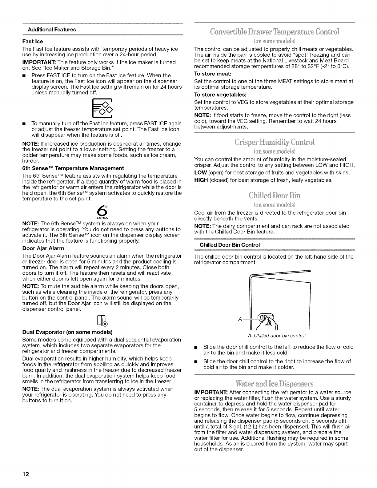
1. Remove the Produce Preserver pouches from their packaging.
irFreshFlow
produce preserver
CAUTION ATTENTION
IRRITANT IRRITANT
Read cautions on back, Life les mises en garde au dos,
Replacing the Air Filter
The disposable air filter should be replaced every 6 months, when
the status indicator has completely changed from white to red.
To order a replacement air filter, see "Accessories."
1. Remove the old air filter by squeezing in on the side tabs.
2. Remove the old status indicator.
3. Install the new air filter and status indicator using the
instructions in the previous sections.
On some models, your refrigerator's accessory packet includes a
Produce Preserver, which should be installed prior to use. On
some models, the Produce Preserver is already installed at the
factory.
The Produce Preserver absorbs ethylene, allowing the ripening
process of many produce items to slow down. As a result, certain
produce items will stay fresh longer.
Installing the Produce Preserver (on some models)
CAUTION: IRRITANT
MAY IRRITATE EYES AND SKIN. DANGEROUS FUMES
FORM WHEN MIXED WITH OTHER PRODUCTS.
Do not mix with cleaning products containing ammonia,
bleach or acids. Do not get in eyes, on skin or clothing. Do
not breathe dust. Keep out of reach of children.
FIRST AID TREATMENT: Contains potassium
permanganate. If swallowed, call a Poison Control Center or
doctor immediately. Do not induce vomiting. If in eyes, rinse
with water for 15 minutes. If on skin, rinse with water.
The Produce Preserver pouches should be installed in their
housing, which is located along an interior side wall of the crisper
or convertible drawer.
....... w_i_!p__i_n _n_,_ N_ N! _ _ ....
2. Lift up on the housing in order to remove it from its mounting
tab along the wall.
3. Open the housing by pulling up and out on the back of the top
of the housing.
4. Place both pouches inside the housing, then snap the housing
back together.
5. Place the housing back on the mounting tab along the wall.
Installing the Status Indicator (on some models)
The Produce Preserver comes with a status indicator, which
should be activated and installed at the same time the pouch is
installed.
1. Place the indicator face-down on a firm, flat surface.
2. Apply pressure to the bubble on the back of the indicator, until
the bubble pops to activate the indicator.
3. Slide open the cap on the Produce Preserver housing.
4. Place the indicator in the top of the housing, facing outward.
5. Slide the cap closed, and check that the indicator is visible
through the rectangular hole in the cap.
NOTE: The cap will not easily close if the indicator's rear
bubble has not been popped.
Replacing the Produce Preserver (on some models)
The disposable pouches should be replaced every 6 months,
when the status indicator has completely changed from white to
red.
To order replacements, see "Accessories."
1. Remove the old pouches from the Produce Preserver housing.
2. Remove the old status indicator.
3. Install the new pouches and status indicator using the
instructions in the previous sections.
NOTE: For best performance, always use two pouches.
10
REFRIGERATORUSE
RECOMMENDED
The refrigerator and freezer controls are located on the dispenser
panel.
IMPORTANT: The display screen on the dispenser control panel
will turn off automatically and enter "sleep" mode when the
control buttons and dispenser pads have not been used for
2 minutes or more. While in "sleep" mode, the first press of a
control button will only reactivate the display screen, without
changing any settings. After reactivation, changes to any settings
can then be made. If no changes are made within 2 minutes, the
display will re-enter "sleep" mode.
• Touch any control button on the dispenser panel to activate
the display screen. The home screen will appear as shown.
I I
Adjusting the Controls
For your convenience, your refrigerator and freezer controls are
preset at the factory. When you first install your refrigerator, make
sure that the controls are still set to the "mid-settings." The factory
recommended set points are 37°F (3°C) for the refrigerator and
0°F (-18°C) for the freezer.
IMPC RTAN1"."
• Wait 24 hours before you put food into the refrigerator. If you
add food before the refrigerator has cooled completely, your
food may spoil.
NOTE: Adjusting the set points to a colder than
recommended setting will not cool the compartments any
faster.
If the temperature is too warm or too cold in the refrigerator or
freezer, first check the air vents to be sure they are not
blocked before adjusting the controls.
The preset settings should be correct for normal household
usage. The controls are set correctly when milk or juice is as
cold as you like and when ice cream is firm.
Wait at least 24 hours between adjustments. Recheck the
temperatures before other adjustments are made.
To view and adjust the set points, press and hold the TEMP
button for 3 seconds. When adjust mode is activated, adjusting
information will appear on the display screen.
F_,DGE --'--I--II OF
BACK UNITS SELECTZONE V A <0_ :RV
NOTE: To view Celsius temperatures, press the LIGHT button
when adjust mode is activated. To return the display setting to
Fahrenheit, press LIGHT again.
• When adjust mode is activated, the display screen shows the
refrigerator set point and "FRIDGE" appears.
Press LOCK to raise the set point, or press FAST ICE to lower
the set point.
When you have finished viewing (and adjusting if desired) the
refrigerator set point, press TEMP to change the display to
show the freezer set point. When the zone has been changed,
"FREEZER" appears on the display screen.
Press LOCK to raise the set point, or press FAST ICE to lower
the set point.
When you have finished viewing (and adjusting if desired) both
the refrigerator and freezer set points, press FILTER to save
the settings.
NOTE: To exit without saving changes, press ICETYPE at any
time while in adjust mode, or allow about 60 seconds of
inactivity and adjust mode will turn off automatically.
When adjusting temperature set points, use the following chart as
a guide.
CONDITION: TEMPERATURE
ADJUSTMENT:
REFRIGERATOR too cold REFRIGERATOR Setting
1o higher
REFRIGERATOR too warm REFRIGERATOR Setting
1o lower
FREEZER too cold FREEZER Setting
1o higher
FREEZER too warm / FREEZER Setting
Too little ice 1o lower
The set point range for the refrigerator is 33°F to 45°F (0°C to
7°C). The set point range for the freezer is -5°F to 5°F (-21 °C to
-15°C).
Cooling On/Off
Your refrigerator and freezer will not cool when cooling is
turned off.
• TOturn cooling off, press and hold the LOCK and FILTER
buttons at the same time for 3 seconds.
IMPORTANT: To avoid unintentionally locking the dispenser
or changing other settings, be sure to press both buttons at
exactly the same time.
When cooling is off, "COOLING OFF" will appear on the
display screen.
Press and hold LOCK and FILTER for 3 seconds again to turn
cooling back on.
11
Additional Features
Fast Ice
The Fast Ice feature assists with temporary periods of heavy ice
use by increasing ice production over a 24-hour period.
IMPORTANT: This feature only works if the ice maker is turned
on. See "Ice Maker and Storage Bin."
• Press FAST ICE to turn on the Fast Ice feature. When the
feature is on, the Fast Ice icon will appear on the dispenser
display screen. The Fast Ice setting will remain on for 24 hours
unless manually turned off.
%
• Tomanually turn off the Fast Ice feature, press FAST ICE again
or adjust the freezer temperature set point. The Fast Ice icon
will disappear when the feature is off.
NOTE: If increased ice production is desired at all times, change
the freezer set point to a lower setting. Setting the freezer to a
colder temperature may make some foods, such as ice cream,
harder.
6th Sense TM Temperature Management
The 6th Sense TM feature assists with regulating the temperature
inside the refrigerator. If a large quantity of warm food is placed in
the refrigerator or warm air enters the refrigerator while the door is
held open, the 6th Sense TM system activates to quickly restore the
temperature to the set point.
The control can be adjusted to properly chill meats or vegetables.
The air inside the pan is cooled to avoid "spot" freezing and can
be set to keep meats at the National Livestock and Meat Board
recommended storage temperatures of 28° to 32°F (-2° to 0°C).
To store meat:
Set the control to one of the three MEAT settings to store meat at
its optimal storage temperature.
To store vegetables:
Set the control to VEG to store vegetables at their optimal storage
temperatures.
NOTE: If food starts to freeze, move the control to the right (less
cold), toward the VEG setting. Remember to wait 24 hours
between adjustments.
You can control the amount of humidity in the moisture-sealed
crisper. Adjust the control to any setting between LOW and HIGH.
LOW (open) for best storage of fruits and vegetables with skins.
HIGH (closed) for best storage of fresh, leafy vegetables.
6
sense
NOTE: The 6th Sense TM system is always on when your
refrigerator is operating. You do not need to press any buttons to
activate it. The 6th Sense TM icon on the dispenser display screen
indicates that the feature is functioning properly.
Door Ajar Alarm
The Door Ajar Alarm feature sounds an alarm when the refrigerator
or freezer door is open for 5 minutes and the product cooling is
turned on. The alarm will repeat every 2 minutes. Close both
doors to turn it off. The feature then resets and will reactivate
when either door is left open again for 5 minutes.
NOTE: To mute the audible alarm while keeping the doors open,
such as while cleaning the inside of the refrigerator, press any
button on the control panel. The alarm sound will be temporarily
turned off, but the Door Ajar icon will still be displayed on the
dispenser control panel.
Dual Evaporator (on some models)
Some models come equipped with a dual sequential evaporation
system, which includes two separate evaporators for the
refrigerator and freezer compartments.
Dual evaporation results in higher humidity, which helps keep
foods in the refrigerator from spoiling as quickly and improves
food quality and freshness in the freezer due to decreased freezer
burn. In addition, the dual evaporation system helps keep food
smells in the refrigerator from transferring to ice in the freezer.
NOTE: The dual evaporation system is always activated when
your refrigerator is operating. You do not need to press any
buttons to turn it on.
Cool air from the freezer is directed to the refrigerator door bin
directly beneath the vents.
NOTE: The dairy compartment and can rack are not associated
with the Chilled Door Bin feature.
Chilled Door BinControl
The chilled door bin control is located on the left-hand side of the
refrigerator compartment.
A"--
A. Chilled door bin control
Slide the door chill control to the left to reduce the flow of cold
air to the bin and make it less cold.
Slide the door chill control to the right to increase the flow of
cold air to the bin and make it colder.
IMPORTANT: After connecting the refrigerator to a water source
or replacing the water filter, flush the water system. Use a sturdy
container to depress and hold the water dispenser pad for
5 seconds, then release it for 5 seconds. Repeat until water
begins to flow. Once water begins to flow, continue depressing
and releasing the dispenser pad (5 seconds on, 5 seconds off)
until a total of 3 gal. (12 L) has been dispensed. This will flush air
from the filter and water dispensing system, and prepare the
water filter for use. Additional flushing may be required in some
households. As air is cleared from the system, water may spurt
out of the dispenser.
12
NOTES:
• The dispensing system will not operate when the freezer door
is open.
• Allow 24 hours for the refrigerator to cool down and chill
water.
Allow 24 hours to produce the first batch of ice. Discard the
first three batches of ice produced. Wait 72 hours for full ice
production.
The display screen on the dispenser control panel will turn off
automatically and enter "sleep" mode when the control
buttons and dispenser pads have not been used for 2 minutes
or more. While in "sleep" mode, the first press of a control
button will only reactivate the display screen, without
changing any settings. After reactivation, changes to any
settings can then be made. If no changes are made within
2 minutes, the display will re-enter "sleep" mode.
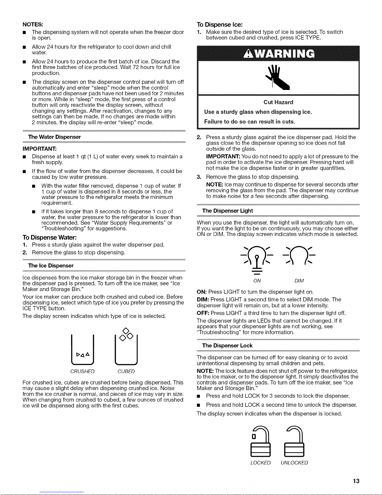
To Dispense Ice:
1. Make sure the desired type of ice is selected. To switch
between cubed and crushed, press ICE TYPE.
Cut Hazard
Use a sturdy glass when dispensing ice.
Failure to do so can result in cuts.
The Water Dispenser
IMPO RTANT:
• Dispense at least 1 qt (1 L) of water every week to maintain a
fresh supply.
• If the flow of water from the dispenser decreases, it could be
caused by low water pressure.
With the water filter removed, dispense 1 cup of water. If
1 cup of water is dispensed in 8 seconds or less, the
water pressure to the refrigerator meets the minimum
requirement.
If it takes longer than 8 seconds to dispense 1 cup of
water, the water pressure to the refrigerator is lower than
recommended. See "Water Supply Requirements" or
"Troubleshooting" for suggestions.
To Dispense Water:
1. Press a sturdy glass against the water dispenser pad.
2. Remove the glass to stop dispensing.
The Ice Dispenser
Ice dispenses from the ice maker storage bin in the freezer when
the dispenser pad is pressed. To turn off the ice maker, see "Ice
Maker and Storage Bin."
Your ice maker can produce both crushed and cubed ice. Before
dispensing ice, select which type of ice you prefer by pressing the
ICE TYPE button.
The display screen indicates which type of ice is selected.
2=
Press a sturdy glass against the ice dispenser pad. Hold the
glass close to the dispenser opening so ice does not fall
outside of the glass.
IMPORTANT: You do not need to apply a lot of pressure to the
pad in order to activate the ice dispenser. Pressing hard will
not make the ice dispense faster or in greater quantities.
3=
Remove the glass to stop dispensing.
NOTE: Ice may continue to dispense for several seconds after
removing the glass from the pad. The dispenser may continue
to make noise for a few seconds after dispensing.
The Dispenser Light
When you use the dispenser, the light will automatically turn on.
If you want the light to be on continuously, you may choose either
ON or DIM. The display screen indicates which mode is selected.
;©:-
ON DIM
ON: Press LIGHT to turn the dispenser light on.
DIM: Press LIGHT a second time to select DIM mode. The
dispenser light will remain on, but at a lower intensity.
OFF: Press LIGHT a third time to turn the dispenser light off.
The dispenser lights are LEDs that cannot be changed. If it
appears that your dispenser lights are not working, see
"Troubleshooting" for more information.
CRUSHED CUBED
For crushed ice, cubes are crushed before being dispensed. This
may cause a slight delay when dispensing crushed ice. Noise
from the ice crusher is normal, and pieces of ice may vary in size.
When changing from crushed to cubed, a few ounces of crushed
ice will be dispensed along with the first cubes.
The Dispenser Lock
The dispenser can be turned off for easy cleaning or to avoid
unintentional dispensing by small children and pets.
NOTE: The lock feature does not shut off power to the refrigerator,
to the ice maker, or to the dispenser light. It simply deactivates the
controls and dispenser pads. To turn off the ice maker, see "Ice
Maker and Storage Bin."
• Press and hold LOCK for 3 seconds to lock the dispenser.
• Press and hold LOCK a second time to unlock the dispenser.
The display screen indicates when the dispenser is locked.
LOCKED UNLOCKED
13
Allow 24 hours to produce the first batch of ice. Discard the
first three batches of ice produced.
The quality of your ice will be only as good as the quality of the
water supplied to your ice maker. Avoid connecting the ice
maker to a softened water supply. Water softener chemicals
(such as salt) can damage parts of the ice maker and lead to
poor quality ice. If asoftened water supply cannot be avoided,
make sure the water softener is operating properly and is well
maintained.
Do not use anything sharp to break up the ice in the storage
bin. This can cause damage to the ice container and the
dispenser mechanism.
• Do not store anything on top of or in the ice maker or storage
bin.
Style I
Turning the Ice Maker On/Off:
The On/Off switch can only be accessed when the ice storage bin
has been removed. The switch is located on the freezer door, on
the left side of the wall that surrounds the ice storage bin. See the
following section for bin removal instructions.
OnO.;I
Ice Maker Control
To turn on the ice maker, slide the control to the ON (left)
position.
• To manually turn off the ice maker, slide the control to the OFF
(right) position.
NOTE: The ice maker has an automatic shutoff to keep the
storage bin from overfilling during normal operation. The ice
maker sensors will automatically stop ice production, but the
control will remain in the ON (left) position.
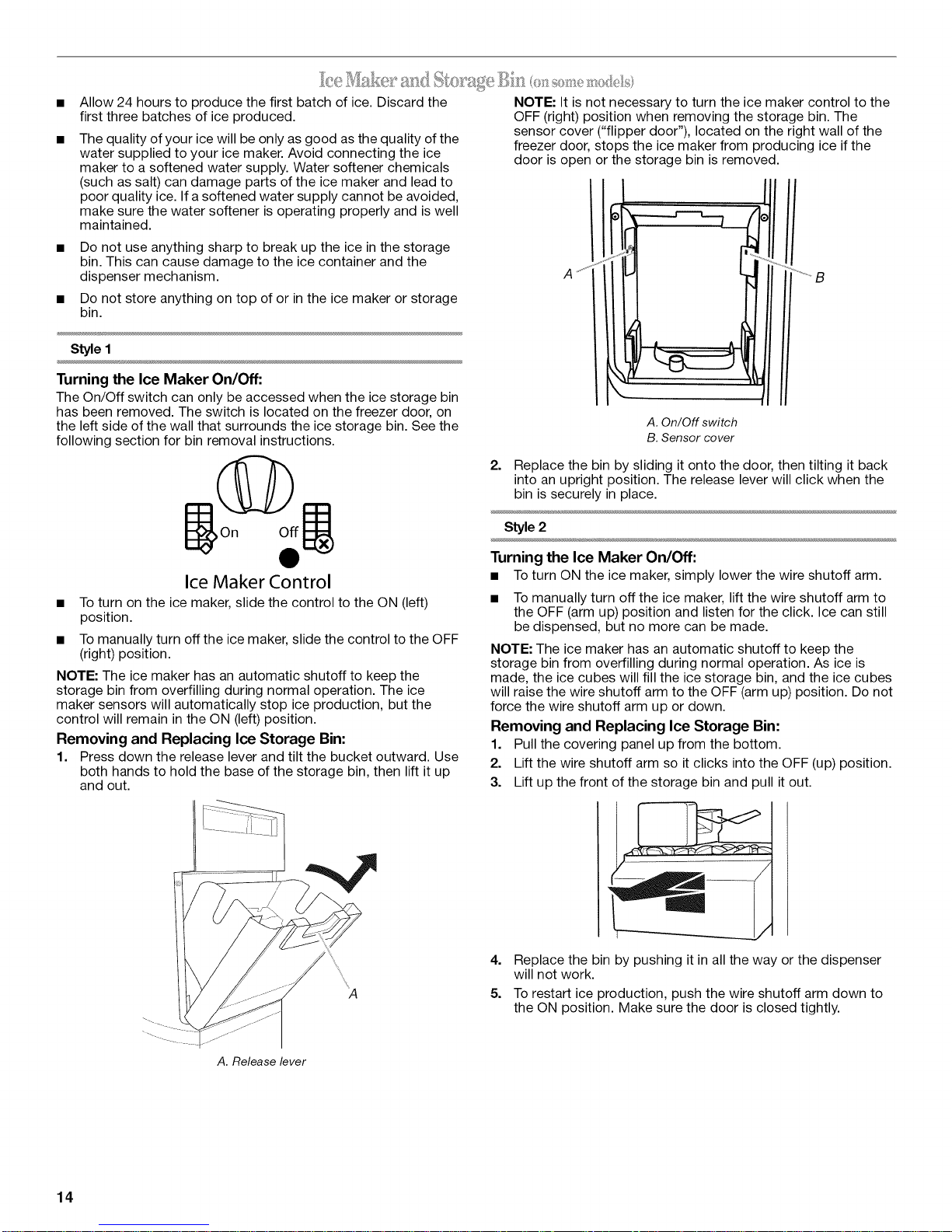
Removing and Replacing Ice Storage Bin:
1. Press down the release lever and tilt the bucket outward. Use
both hands to hold the base of the storage bin, then lift it up
and out.
NOTE: It is not necessary to turn the ice maker control to the
OFF (right) position when removing the storage bin. The
sensor cover ("flipper door"), located on the right wall of the
freezer door, stops the ice maker from producing ice if the
door is open or the storage bin is removed.
A. On/Off switch
B. Sensor cover
2. Replace the bin by sliding it onto the door, then tilting it back
into an upright position. The release lever will click when the
bin is securely in place.
Style 2
Turning the Ice Maker On/Off:
• To turn ON the ice maker,simply lower thewire shutoff arm.
• To manually turn off the ice maker, lift the wire shutoff arm to
the OFF (arm up) position and listen for the click. Ice can still
be dispensed, but no more can be made.
NOTE: The ice maker has an automatic shutoff to keep the
storage bin from overfilling during normal operation. As ice is
made, the ice cubes will fill the ice storage bin, and the ice cubes
will raise the wire shutoff arm to the OFF (arm up) position. Do not
force the wire shutoff arm up or down.
Removing and Replacing Ice Storage Bin:
1. Pull the covering panel up from the bottom.
2. Lift the wire shutoff arm so it clicks into the OFF (up) position.
3. Lift up the front of the storage bin and pull it out.
"....
A. Release lever
14
4.
Replace the bin by pushing it in all the way or the dispenser
will not work.
5.
To restart ice production, push the wire shutoff arm down to
the ON position. Make sure the door is closed tightly.
 Loading...