

Whirlpool WPH43M, WPC4336AM, WPC43M, WPC4348AM, WPH4324AM Installation Instructions Manual
...
SELF-CONTAINED PACKAGE AIR CONDITIONERS AND
HEAT PUMP UNITS INSTALLATION INSTRUCTIONS
Table of Contents
SAFETY INSTRUCTIONS............................................................... 2
TO THE INSTALLER.......................................................................3
IMPORTANT NOTE TO THE OWNER REGARDING
PRODUCT WARRANTY.................................................................3
SHIPPING INSPECTION ................................................................3
REPLACEMENT PARTS ................................................................3
CODES AND REGULATIONS........................................................3
EPA Regulations...........................................................................3
National Codes.............................................................................3
MAJOR COMPONENTS ................................................................3
PREINSTALLATION CHECKS.......................................................3
Clearances and Accessibility.......................................................4
Unit Location ................................................................................ 4
Ground Level Preinstallation Details............................................4
Rooftop Preinstallation Details.....................................................4
Roof Curb Installations Only ........................................................4
Rigging Details .............................................................................5
CIRCULATING AIR AND FILTERS................................................5
Airflow Conversion .......................................................................5
Ductwork ......................................................................................5
Filters............................................................................................6
Connect Condensate Drain .........................................................6
WIRING............................................................................................6
High Voltage Wiring......................................................................7
Low Voltage Wiring ......................................................................7
Internal Wiring...............................................................................7
START-UP, ADJUSTMENTS AND CHECKS................................8
Start-up Procedure and Checklist—Cooling Cycle.....................8
Start-up Procedure—Heat Pump ................................................8
Final System Checks....................................................................8
Components.................................................................................8
HEAT PUMP OPERATION .............................................................9
Cooling Cycle ...............................................................................9
Heating Cycle ...............................................................................9
Defrost Control ...........................................................................10
Suggested Field Testing/Troubleshooting.................................10
Airflow Measurement and Adjustment.......................................10
Speed Tap Adjustments for Indoor Blower Motor.....................11
Blower Performance Data..........................................................11
Refrigerant Charge Checks........................................................12
ELECTRICAL ADJUSTMENTS....................................................13
SYSTEM MAINTENANCE ............................................................14
Service........................................................................................14
TROUBLESHOOTING CHART.....................................................15
APPENDIX.....................................................................................16
Wiring Diagram—WPC4336AM.................................................16
Wiring Diagram—WPC43(48-60)AM..........................................17
Wiring Diagram—WPH43(24 - 42)AM........................................18
Wiring Diagram—WPH43(48, 60)AM .........................................19
Product Dimensions...................................................................20
ASSISTANCE OR SERVICE.........................................................20
ATTENTION INSTALLATION PERSONNEL
Prior to installation, thoroughly familiarize yourself with this instruction manual.
Observe all safety warnings.
During installation or repair, caution is to be observed.
It is your responsibility to install the product safely and to educate the customer on its safe use.
Placeholder
for Bar
Keep this literature in a safe place for future reference.
Whirlpool Gold® Models
WPH43M, WPC43M
WPIO-356A
Code
These installation instructions cover the outdoor
installation of self-contained package air conditioners and
heating units. See the Specification Sheets applicable to
your model for information regarding accessories. Please
contact your distributor or our website for the applicable
Specification Sheets referred to in this manual.
Tradewinds Distributing Company, LLC
14610 Breakers Drive
Jacksonville, Florida 32258
SAFETY INSTRUCTIONS
The following symbols and labels are used throughout this manual to indicate immediate or potential safety hazards. It is the owner’s
and installer’s responsibility to read and comply with all safety information and instructions accompanying these symbols. Failure to
heed safety information increases the risk of personal injury, property damage and/or product damage.
Recognize this symbol as a safety precaution.
WARNING
Hazards or unsafe practices could result in property
damage, product damage, severe personal injury or death.
Goodman 1
CAUTION
Hazards or unsafe practices may result in property
damage, product damage, personal injury or death.
WARNING
Do not connect to or use any device that is not designcertified for use with this unit. Serious property damage,
personal injury, reduced unit performance and/or hazardous
conditions may result from the use of such non-approved
devices.
Goodman 36
WARNING
HIGH VOLTAGE!
Disconnect ALL power before servicing.
Multiple power sources may be present.
Failure to do so may cause property damage,
personal injury or death.
Goodman 42
WARNING
Connecting unit ductwork to unauthorized heat producing
devices such as a fireplace insert, stove, etc., may result
in property damage, fire, carbon monoxide poisoning,
explosion, personal injury or death.
Goodman 98
WARNING
This product contains or produces a chemical or
chemicals which may cause serious illness or death and
which are known to the State of California to cause
cancer, birth defects or other reproductive harm.
Goodman 45
WARNING
To avoid property damage, personal injury or death, do
not use this furnace if any part of the furnace has been
under water. Immediately call a qualified service technician
to inspect the furnace and to replace any part of the
control system and any gas control having been under
water.
Goodman 81
WARNING
This unit must not be used as a “construction heater”
during the finishing phases of construction on a new
structure. This type of use may result in premature failure
of the unit due to extremely low return air temperatures
and exposure to corrosive or very dirty atmospheres.
Goodman 79
WARNING
To prevent the risk of property damage, personal injury, or
death, do not store combustible materials or use gasoline
or other flammable liquids or vapors in the vicinity of this
unit.
WARNING
Installation and repair of this unit should
be performed ONLY by individuals meeting
the requirements of an “Entry Level Technician,”
at a minimum, as specified by the Air-Conditioning,
Heating and Refrigeration Institute (AHRI). Attempting
to install or repair this unit without such background may
result in product damage, personal injury or death.
TO THE INSTALLER
Carefully read all instructions for the installation prior to installing
unit. Make sure each step or procedure is understood and any
special considerations are taken into account before starting
installation. Assemble all tools, hardware and supplies needed to
complete the installation. Some items may need to be purchased
locally.
After deciding where to install unit, closely look over the
location—both the inside and outside of the home. Note any
potential obstacles or problems that might be encountered as
noted in this manual. Choose a more suitable location if
necessary.
2

IMPORTANT NOTE TO THE
OWNER REGARDING
PRODUCT WARRANTY
Your warranty certificate is supplied as a separate document with
the unit installed by your contractor. Read the limited warranty
certificate carefully to determine what is and is not covered. Keep
the warranty certificate in a safe place. If you are unable to locate
the warranty certificate, please contact your installing contractor,
or contact customer service at 1-866-944-7575 to obtain a copy.
To receive the 10-Year Parts Limited Warranty, online registration
must be completed within 60 days of installation. Online
registration is not required in California or Quebec.
Full warranty details and instructions are available at
www.whirlpoolhvac.com.
To register your unit, go to www.whirlpoolhvac.com. Click on the
manufacturer’s Comfort Commitment
the bottom center of the home page. Next, click on the Click
Here to Register Your Product link located at the top center of the
page, and complete the forms in the manner indicated.
TM
Warranty link located at
SHIPPING INSPECTION
Upon receiving the unit, inspect it for damage from shipment.
Claims for damage, either shipping or concealed, should be filed
immediately with the shipping company. Check the unit model
number, specifications, electrical characteristics and accessories
to determine if they are correct. In the event an incorrect unit is
shipped, it must be returned to the supplier and must not be
installed. The manufacturer assumes no responsibility for
installation of incorrectly shipped units.
REPLACEMENT PARTS
When reporting shortages or damages, or ordering repair parts,
give the complete product model and serial numbers as stamped
on the product. Replacement parts for this product are available
through your contractor or local distributor. For the location of
your nearest distributor, consult the white business pages, the
yellow page section of the local telephone book or contact:
Tradewinds Distributing Company, LLC
14610 Breakers Drive
Jacksonville, Florida 32258
1-866-944-7575
If you are replacing an air handler, the system must be
manufacturer-approved and Air-Conditioning, Heating, and
Refrigeration Institute (AHRI) matched.
NOTE: Installation of unmatched systems is strongly
discouraged.
CODES AND REGULATIONS
The WPC/WPH M-series air conditioners and heat pumps are
designed for outdoor use only. WPH M-Series is available in
cooling capacities of 2, 2¹⁄₂, 3, 3¹⁄₂, 4 and 5 nominal tons of
cooling. WPC M-Series is available in cooling capacities of 3,
4 and 5 nominal tons of cooling. Optional field-installed heat kits
are available in 5, 8, 10, 15 and 20 kW. The units can be easily
installed in manufactured or modular homes with existing highstatic ductwork. The units can also be easily converted to
accommodate a plenum for normal or low-static applications.
The WPC/WPH M-series are self-contained packaged units so
the only connections needed for installation are the supply and
return ducts, the line and low voltage wiring and drain
connection. The units are ETL listed and AHRI certified.
The information on the rating plate is in compliance with the FTC
and DOE rating for single-phase units. The efficiency ratings of
these units are a product of thermal efficiency determined under
continuous operating conditions independent of any installed
system.
EPA Regulations
IMPORTANT: The United States environmental protection
agency (EPA) has issued various regulations regarding the
introduction and disposal of refrigerants in this unit. Failure to
follow these regulations may harm the environment and can lead
to the imposition of substantial fines. Because regulations may
vary due to passage of new laws, we suggest a certified
technician perform any work done on this unit. Should you have
any questions, please contact the local office of the EPA.
National Codes
This product is designed and manufactured to permit installation
in accordance with National Codes. It is the installer’s
responsibility to install the product in accordance with National
Codes and/or prevailing local codes and regulations.
MAJOR COMPONENTS
The unit includes a hermetically sealed refrigerating system
(consisting of a compressor, condenser coil, evaporator coil with
flowrator), an indoor blower, a condenser fan and all necessary
internal electrical wiring. The heat pump also includes a reversing
valve, solenoid, defrost thermostat and control and loss of charge
protection. The system is factory-evacuated, charged and
performance tested. Refrigerant amount and type are indicated
on rating plate.
PREINSTALLATION CHECKS
Before attempting any installation, the following points should be
considered:
■ Structural strength of supporting members
■ Clearances and provision for servicing
■ Power supply and wiring
■ Air duct connections
■ Drain facilities and connections
■ Location may be on any 4 sides of a home, manufactured or
modular, to minimize noise.
Clearances and Accessibility
The unit is designed to be located outside the building with
unobstructed condenser air inlet and discharge. Additionally, the
unit must be situated to permit access for service and
installation. Condenser air enters from 3 sides. Air discharges
upward from the top of the unit. Refrigerant gauge connections
are made on the right side of the unit as you face the compressor
compartment. Electrical connections can be made either on the
right, bottom or duct panel side of the unit. The best and most
common application is for the unit to be located 10" (25.4 cm)
from the wall (4" [10.2 cm]) minimum) with the connection side
facing the wall. Close to the wall application minimizes exposed
wiring.
3
Close to the wall application assures free, unobstructed air to the
other 2 sides. In more confined application spaces, such as
corners, provide a minimum 10" (25.4 cm) clearance on all air
inlet sides. Allow 18" (45.7 cm) minimum for service access to the
compressor compartment and controls. The top of the unit
should be completely unobstructed. If units are to be located
under an overhang, there should be a minimum of 36" (91.4 cm)
clearance and provisions made to deflect the warm discharge air
out from the overhang.
■ To avoid possible property damage or personal injury, the
roof must have sufficient structural strength to carry the
weight of the unit(s) and snow or water loads as required by
local codes. Consult a structural engineer to determine the
weight capabilities of the roof.
■ The unit may be installed directly on wood floors or on Class
A, Class B or Class C roof covering material.
■ To avoid possible personal injury, a safe, flat surface for
service personnel should be provided.
Unit Location
Consider the affect of outdoor fan noise on conditioned space
and any adjacent occupied space. It is recommended that the
unit be placed so that the condenser air discharge does not blow
toward windows less than 25 ft (7.6 m) away. Consideration
should also be given to shade and unit appearance.
Heat pumps require special location consideration in areas of
heavy snow accumulation and/or areas with prolonged
continuous subfreezing temperatures. Heat pump unit bases
have holes under the outdoor coil to permit drainage of defrost
water accumulation. The unit must be situated to permit free
unobstructed drainage of the defrost water and ice. A minimum
2" (5 cm) clearance under the outdoor coil is required in the
milder climates.
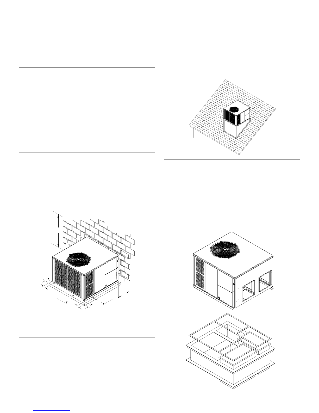
Ground Level Preinstallation Details
The unit should be set on a solid, level foundation—preferably a
concrete slab at least 4" (10.2 cm) thick. The slab should be
above ground level and surrounded by a graveled area for good
drainage. Any slab used as a unit’s foundation should not adjoin
the building as it is possible that sound and vibration may be
transmitted to the structure.
Ground Level Installation
Rooftop Installation
Roof Curb Installations Only
NOTE: Sufficient structural support must be determined prior to
locating and mounting the curb and package unit.
Curb insulation, cant strips, flashing and general roofing material
are furnished by the contractor.
Curbing must be installed in compliance with the National
Roofing Contractors Association Manual. Construct ductwork
using current industry guidelines. The ductwork must be placed
into the roof curb before mounting the package unit.
A
B
D
C
C
B
A. 48" (121.9 m) minimum
B. 12" (30.5 cm) minimum
C. 36" (91.4 cm) minimum service clearance
D. 4" (10.2 cm) minimum
Rooftop Preinstallation Details
■ Ensure that the roof is weather tight and allows proper
drainage of condensation.
■ Use steel or treated wood beams as unit support for load
distribution.
NOTE: To ensure proper condensate drainage, unit must be
installed in a level position.
Roof Curb Installation
4
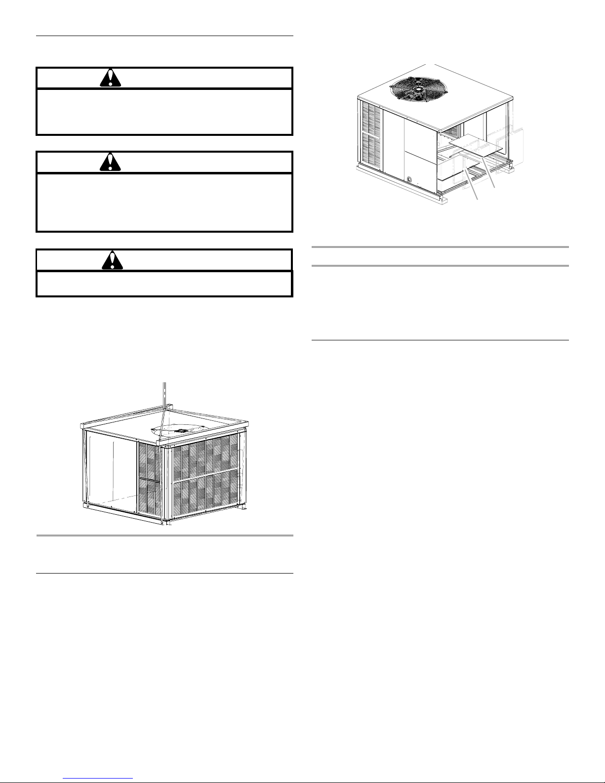
Rigging Details
WARNING
To prevent property damage, the unit should remain in an
upright position during all rigging and moving operations.
To facilitate lifting and moving when a crane is used,
place the unit in an adequate cable sling.
WARNING
To prevent property damage, personal injury or death,
ensure the roof has sufficient structural strength to carry
the weight of the unit(s), roof curb, snow loads and water
loads as required by local codes. Consult a structural
engineer to determine the weight capabilities of the roof.
Duct Cover Installations—Down-Discharge
Remove the panels for down-discharge duct applications.
B
A
A. Supply air panel
B. Return air panel
CAUTION
To avoid possible personal injury, a safe, flat surface for
service personnel should be provided.
IMPORTANT: If you are using bottom discharge with roof curb,
ductwork should be attached to the curb prior to installing the
unit. Lower unit carefully onto roof mounting curb. While rigging
unit, center of gravity will cause condenser end to be lower than
supply air end.
Rigging
CIRCULATING AIR AND FILTERS
Airflow Conversion
Units can easily be converted from horizontal to down-discharge
airflow delivery. In down-discharge or high-static installations, the
installer should measure the total external static and review the
blower performance charts before performing the installation. In
some installations, it will be necessary to change the blower
speed to provide proper airflow.
Down-Discharge Applications
Cut insulation around bottom openings and remove panels from
the bottom of the unit, saving the screws holding the panels in
place.
NOTE: Down-discharge models require installation of horizontal
duct kit Number 20464501PDGK (medium chassis) and Number
20464502PDGK (large chassis).
Ductwork
Duct systems and register sizes must be properly designed for
the C.F.M. and external static pressure rating of the unit.
Ductwork should be designed in accordance with the
recommended methods of Air Conditioning Contractors of
America Manual D (Residential) or Manual Q (Commercial).
All ductwork exposed to the outdoors must include a
weatherproof barrier and adequate insulation. A duct system
should be installed in accordance with Standards of the National
Board of Fire Underwriters for the Installation of Air Conditioning,
Warm Air Heating and Ventilating Systems. Pamphlets Number
90A and 90B.
The supply duct from the unit through a wall may be installed
without clearance. However, minimum unit clearances must be
maintained. The supply duct should be provided with an access
panel large enough to inspect the air chamber downstream of the
heat exchanger. A cover should be tightly attached to prevent air
leaks.
For duct flange dimensions on the unit, refer to the Unit
Dimension illustration in the appendix.
For down-discharge applications, the ductwork should be
attached to the roof curb prior to installing the unit. Ductwork
dimensions are shown in the roof curb installation manual.
If desired, supply and return duct connections to the unit may be
made with flexible connections to reduce possible unit operating
sound transmission.
5
Filters
CAUTION
To prevent property damage due to fire and loss of
equipment efficiency or equipment damage due to dust
and lint build up on internal parts, never operate unit
without an air filter installed in the return air system.
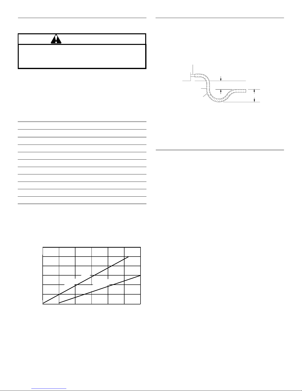
Connect Condensate Drain
The condensate drain connection of the evaporator is a half
coupling of ³⁄₄" N.P.T. A trap must be provided to have proper
condensate drainage.
Condensate Drain Connection
A
Filters are not provided with unit and must be supplied and
externally installed in the return duct system by the installer. An
optional factory-approved internal filter rack may also be used. A
field-installed filter grille is recommended for easy and
convenient access to the filters for periodic inspection and
cleaning. When installing filters, ensure the airflow arrows on the
filter are pointing toward the circulator blower.
Refer to the following unit filter size chart for filter size
information.
Minimum Filter Size
Nominal Size—in. (cm) Nominal Area—sq ft (cm
10 x 20 (25.4 x 50.8) 1.4 (1,301)
14 x 20 (35.6 x 50.8) 1.9 (1,765)
14 x 25 (35.6 x 63.5) 2.4 (2,230)
15 x 20 (38.1 x 50.8) 2.1 (1,951)
16 x 20 (40.6 x 50.8) 2.2 (2,044)
16 x 25 (40.6 x 63.5) 2.8 (2,601)
20 x 20 (50.8 x 50.8) 2.8 (2,601)
20 x 25 (50.8 x 63.5) 3.5 (3,252)
25 x 25 (63.5 x 63.5) 4.3 (3,995)
NOTE: Filters must have adequate face area for the rated
quantity of the unit. See the Air Delivery Table for the
recommended filter size. Size the filters in accordance with their
manufacturer recommendations. Throwaway filters must be sized
for a maximum face velocity of 300 ft per minute.
2
)
Air Delivery Table
Nominal Filter Area
sq ft (cm
(6,503)
(5,574)
(4,645)
(3,716)
(2,787)
(1,858)
2
)
7
6
5
4
3
2
Disposable Filter
Permanent Filter
500 1,000 1,500 2,000 2,500 3,000 3,500
Airflow - SCFM
F
E
D
A. Drain connection
B. 2" (5.1 cm) minimum
C. 3" (7.6 cm) minimum
■ Install the condensate drain trap as shown. Use a ³⁄₄" (1.9 cm)
B
C
D. Positive liquid seal (required)
E. Flexible tubing, hose or pipe
F. U n it
NPT drain connection size or larger.
■ Do not operate without a trap.
■ Unit must be level or slightly inclined toward drain.
WIRING
NOTE: All wiring should be made in accordance with the National
Electrical Code (N.E.C).
Consult your local power company to determine the availability of
sufficient power to operate the unit. Check the voltage, frequency
and phase at the power supply to ensure it corresponds to the
unit’s rated voltage requirement.
In accordance with the N.E.C. or local codes, install a branch
circuit fused disconnect near the unit. Determine wire sizes and
overcurrent protection from the unit nameplate ampacity and in
accordance with Branch Circuit Ampacity chart or the N.E.C. The
wiring should never be sized smaller than is recommended by
either of these 2 sources.
Fuses smaller than that recommended on the rating plate could
result in unnecessary fuse failure or service calls. The use of
protective devices of larger size than indicated could result in
extensive damage to the equipment. The manufacturer bears no
responsibility for damage caused to equipment as result of the
use of larger than is recommended size protective devices.
All units have undergone a run test prior to packaging for
shipment. This equipment has been started at minimum rated
voltage and checked for satisfactory operation.
IMPORTANT: Do not attempt to operate this unit if the voltage is
not within the minimum and maximum voltages shown on
nameplate.
All exterior wiring must be within approved weatherproof conduit.
The unit must be permanently grounded in accordance with local
codes, or in absence of local codes, with N.E.C. ANSI/ NFPA
Number 70-1984 or latest edition by using ground lug in the
control box.
6
 Loading...