

Page 1
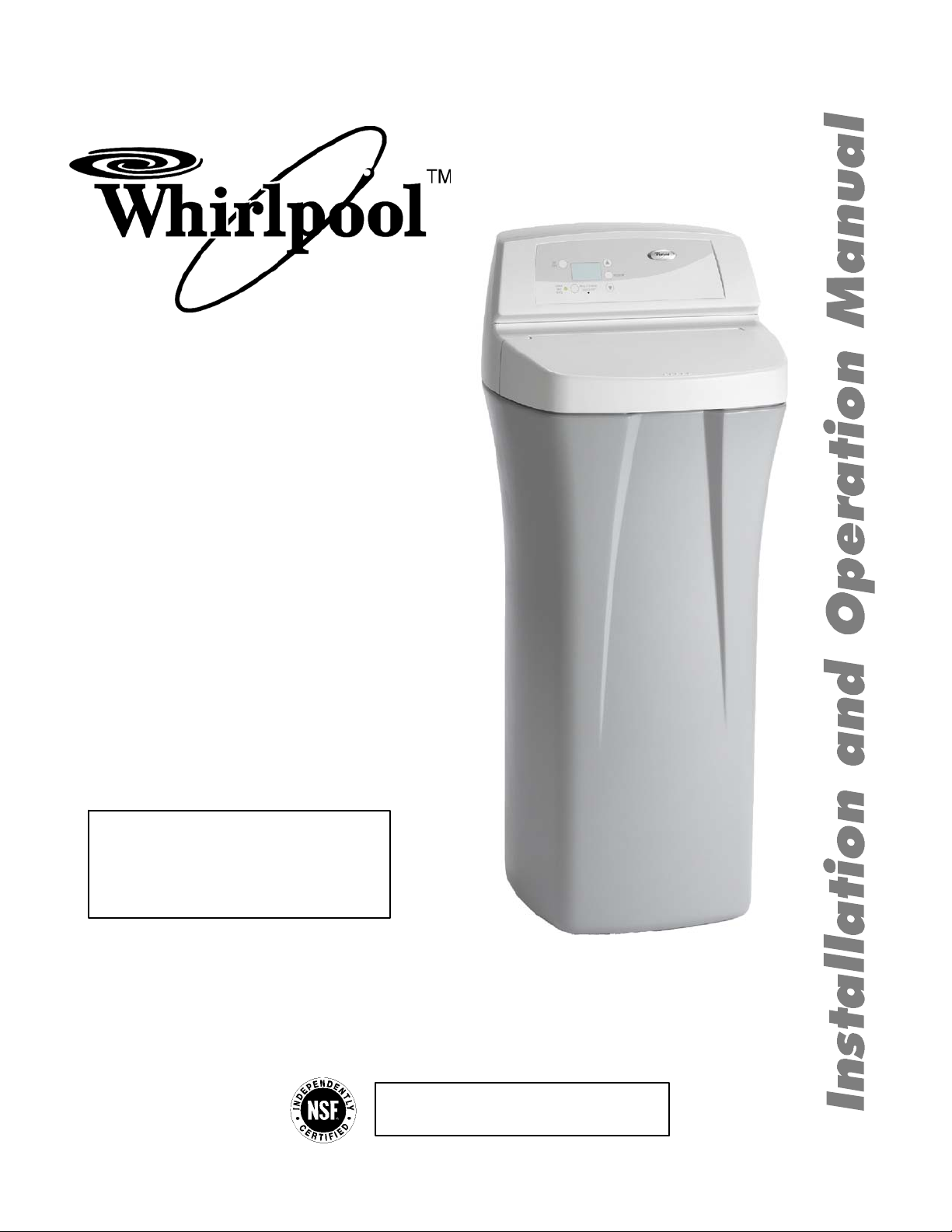
Model WHES20
Model WHES30
How to install, operate and
maintain your Demand
Controlled Water Softener
Do not return water softener to store
If you have questions or concerns when
installing, operating or maintaining your
softener, call our toll free number:
1--866--986--3223
Monday -- Friday, 8 am -- 9 pm EST
NSF International against NSF/ANSI Standard 44
System Tested and C ertified by
forsoftenerperformance.
7283659 (Rev. B 6/8/06)
Product No. 8562921--A
Page 2

Table o f Contents
Water Softener Safety 3..........................................................................
Before You Start 3...............................................................................
Inspect Shipment 4..............................................................................
Water Softener Dimensions 5.....................................................................
Water Conditioning Information 6..................................................................
Water Conditioning 6.........................................................................
How A Water Softener Works 6....................................................................
Softening Cycle 6............................................................................
Regeneration Cycle 6.........................................................................
Installation Requirements 8.......................................................................
Tools and Parts Needed 8.....................................................................
Location Requirements 9......................................................................
Air Gap Requirements 9......................................................................
Valve Drain Requirements 10...................................................................
Planning Installation 11............................................................................
Inlet --- Outlet Plumbing Options 11..............................................................
Installation 12....................................................................................
Turn Off Water Supply 12.......................................................................
Install Brine Tank Overflow Elbow 12.............................................................
Move the Water Softener into Place 13...........................................................
Assemble Inlet and Outlet Plumbing 14..........................................................
Connect Inlet and Outlet Plumbing 14...........................................................
Install Valve Drain Hose 15.....................................................................
Install Salt Storage Tank Overflow Hose 15.......................................................
Tes t f or L ea ks 15..............................................................................
AddWaterandSalttotheSalt StorageTank ...................................................
NO TAG
Sanitize the Softener/Sanitize After Service 16....................................................
Plug in Water Softener 16......................................................................
Program the Water Softener --- Model WHES20 17....................................................
Set Time of Day 17............................................................................
Set Water Hardness Number 18.................................................................
Set Recharge (Regeneration) Time 18...........................................................
Start a Recharge 18...........................................................................
Program the Water Softener --- Model WHES30 19....................................................
Set Time of Day 19............................................................................
Set Water Hardness Number 20.................................................................
Set Recharge (Regeneration) Time 20...........................................................
Start a Recharge 20
Customizing Features / Options---Model WHES20 21..................................................
Recharge 21..................................................................................
Recharge Tonight 21...........................................................................
‘‘Power ---Outage Memory’’ 21..................................................................
Salt Efficiency 22..............................................................................
Customizing Features / Options---Model WHES30 23..................................................
Recharge 23..................................................................................
Recharge Scheduled / Tonight 23...............................................................
SetSaltLevel 23..............................................................................
Electronic Control / ‘‘Power---Outage Memory’’ 24.................................................
Water Flow Indicator 24........................................................................
Salt Efficiency 24..............................................................................
Clean / Clear Water Iron Removal 25............................................................
Clean Feature Minutes 25......................................................................
Maximum Days Between Regenerations 26.......................................................
12 or 24 Hour Clock 26........................................................................
Routine Maintenance 27...........................................................................
Refilling With Salt 27...........................................................................
Breaking A Salt Bridge 27......................................................................
Cleaning the Nozzle and Venturi 28..............................................................
...........................................................................
2
Page 3
Troubleshooting Guide 29.........................................................................
Automatic Electronic Diagnostics 30.............................................................
Manual Advance Diagnostics---Model WHES20 30.................................................
Manual Advance Regeneration Check---Model WHES20 31.........................................
Manual Advance Diagnostics---Model WHES30 32.................................................
Manual Advance Regeneration Check---Model WHES30 33.........................................
Wiring Schematic 35..............................................................................
Warranty 35......................................................................................
Softener Components 36..........................................................................
Water Softener Safety
For installations in the Commonwealth of Massachusetts:
Installation by a licensed plumber is re quired. Plumbing code 248--CMR of the Commonwealth
of Massachusetts must be used for installation.
For installations in the state of California:
You must turn the Salt Efficiency Feature setting to ON. This may initiate more frequent recharges, however, it will operate at 4,000 grains per pound of salt or higher. To turn on the Salt
Efficiency Feature, follow the instructions in the “Salt Efficiency” section of this manual.
Before You Start
See “Location Requirements” section before installing water softener.
Follow the installation instructions carefully. (Failure to install the water softener properly voids the
warranty.)
Before you begin installation, read this entire manual. Then, obtain all the materials and tools you will
need to make the installation.
Check local plumbing and electrical codes.
Use only lead--free solder and flux for all sweat-solder connections, as required by federal code s.
Use care when handling the water softener. Do not turn upside down, drop, or set on sharp protrusions.
Avoid installing in direct sunlight. Excessive sun heat may cause distortion or other damage to
non--metallic parts.
3
Page 4
The water softener requires a minimum water flow of 3 gallons per minute at the inlet. Maximum
allowable inlet water pressure is 125 psi. If daytime pressure is over 80 psi, nighttime pressure may
exceed the maximum. Use a pressure reducing valve if necessary. (Adding a pressure reducing valve
may reduce the flow.) If your home is equipped with a back flow preventer, an expansion tank must
be installed in accordance with local codes and laws.
The water softener works on 24 volt--60 hz electrical power only, supplied by a direct plug--in
transformer (included). Be sure to use the included transformer and plug it into a nominal 120V, 60
cycle household outlet that is properly protected by an overcurrent device such as a circuit breaker or
fuse. If transformer is replaced, use only the authorized service, Class II, 24V 10VA transformer.
This systemis not intended tobe used for treating water that is microbiologically unsafe or of unknown
quality without adequate disinfection before or after the system.
European Directive 2002/96/EC requires all electrical and electronic equipment to be disposed of
according to Waste Electrical and Electronic Equipment (WEEE) requirements. This directive or
similar laws are in place nationally and can vary from region to region. Please refer to your state
and local laws for proper disposal of this equipment.
Inspect Shipment
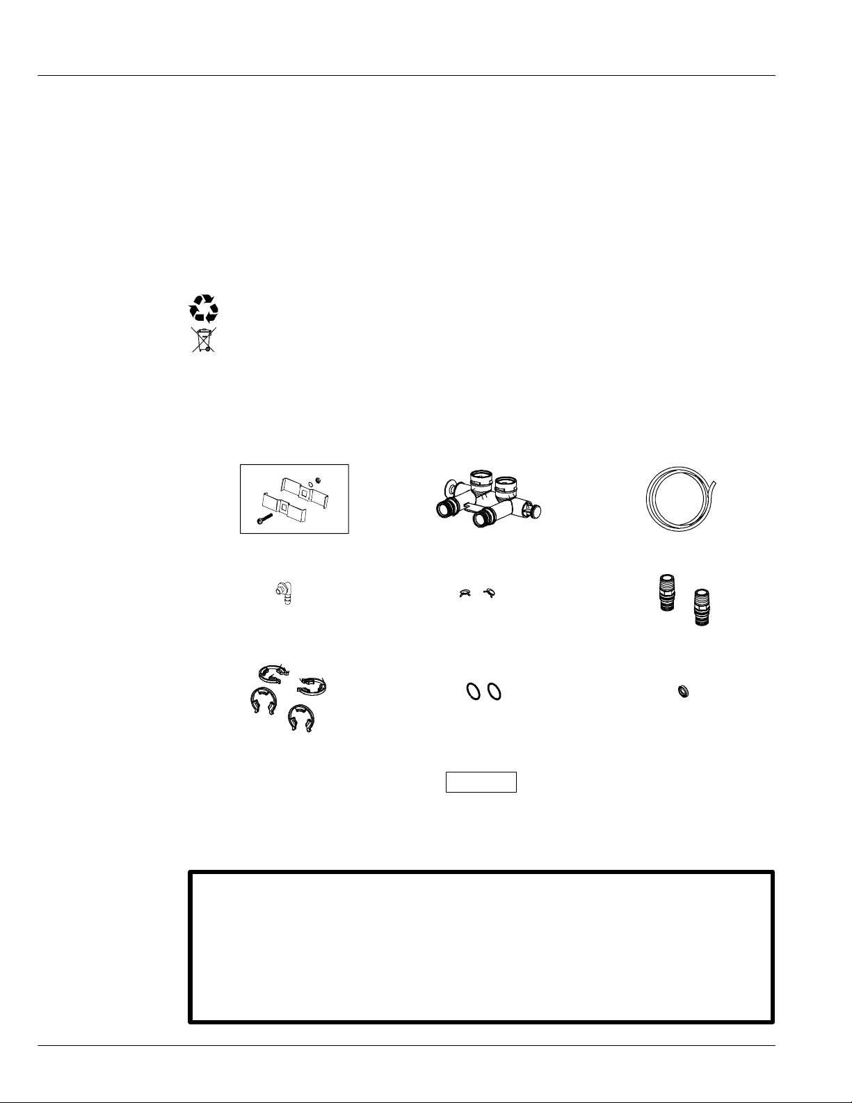
The parts required to assemble and install the water softener are included with the water softener.
Ground clamp Single valve bypass 20 ft. drain hose
Hose adaptor Hose clamps Installation adaptors
Clips O--rings Grommet
Water hardness test strip
Thoroughly check the water softener for possible shipping damage and parts loss. Also inspect and
note any damage to the shipping carton.
Remove and discard (or recycle) all packing materials. To avoid loss of small parts, we suggest you
keep the small parts in the parts bag until you are ready to use them.
Do not return the water softener to store.
If you have any questions, or there are missing parts or damage, please call
1 --- 8 66 --- 9 8 6 --- 3 22 3, M on da y --- Fri da y, 8 a m --- 9 p m E ST.
Before you call please have your model number, date of purchase, water
conditions and number of people living in your home.
4
Page 5
For future reference, enter the following information.
Model No. no
Code n
*Water hardness gpg
Serial No. no
Installation date
**Iron content ppm
n on registration decal (located under salt hole cover) o on shipping carton
* A hardness test strip is provided with your water softener.
** Kits are available at retail hardware stores for testing water hardness and iron content. Some retail
stores will also test your water for a fee.
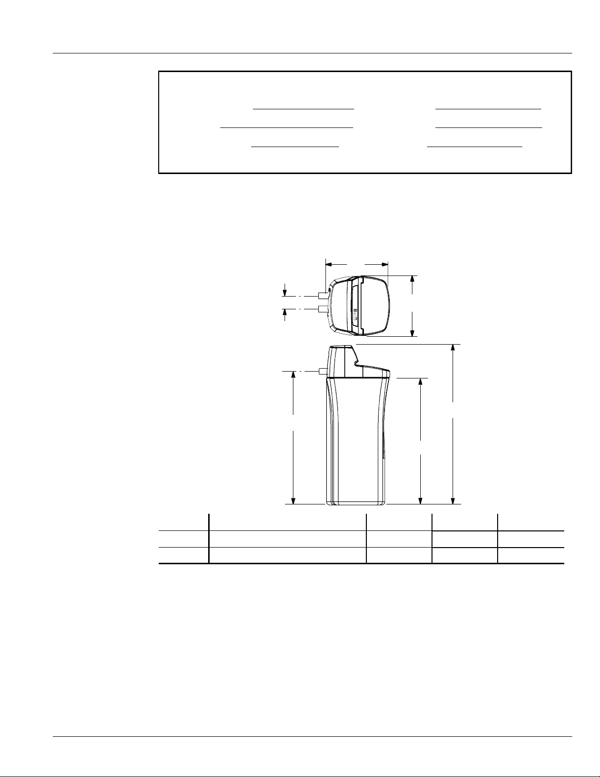
Water Softener Dimensions
19”
3---3/8”
IN
18”
OUT
IN --- OUT
C
A
B
MODEL NOMINAL RESIN TANK SIZE A B C
WHES20 8” DIA. X 35” 36 ---1/2” 35” 43--- 5/16”
WHES30 9” DIA. X 35” 36 ---1/2” 35” 43--- 5/16”
5
Page 6

How a Water Softener Works
Softening Cycle
When the water softener is providing soft water, it is called “service” or the “softening cycle”. During
this cycle, hard water flows from the main water pipe in the household into the water softener. Inside
the resin tank is a bed made up of thousands of tiny, plastic resin beads. As hard water passes through
the bed, each bead attracts and holds the hardness minerals. Water without the hardness minerals (soft
water) flows from the water softener to the rest of the house.
Regeneration Cycle
Eventually the beads become coated with calcium or magnesium ions. At this point, the water softener
needs to replenish the beads with sodium ions. This process is called “regeneration”.
Regeneration occurs when the resin beads are washed with a strong salt water solution. The sodium
forces the calcium and magnesium ions to be released where they are then discharged as waste during
the regeneration cycle. The beads are then ready to once again to collect the hardness minerals
(calcium and magnesium) from the water. Regeneration consists of five cycles; brine fill, brining, brine
rinse, backwash and fast rinse. The total time of the regeneration cycle is approximately two hours.
Water Conditioning Information
Water Conditioning
Water conditioning is the treatment of four general conditions. These are:
Hardness
Iron
Acidity
Sediments
1. Hardness is a term to describe the presence of calcium and magnesium minerals in water. A
chemical analysis accurately measures the amount of minerals in grain weight. For example, one
gallon of water with 5 grains per gallon (gpg) hardness has dissolved minerals, that if solidified,
about equals the size of oneordinary aspirin tablet. One gallonof water, 25gpg hard, has a mineral
content equal in size to 5 a spir in tablets. Water hardness va ries grea tly across the country. It
generally contains from 3 to 100 gpg.
Hardness minerals combine with soap to make a soap curd. The curd greatly reduces the cleaning
action of soap. Precipitated hardness minerals form a crust on cooking utensils, appliances, and
plumbing fixtures. Even the tastes of foods are affected. A water softener removes the hardness
minerals to eliminate these effects, and others.
IMPORTANT: Water softeners using sodium chloride (salt) for regeneration add sodium to the
water. Persons on sodium restricted diets should consider the added sodiumas part of their overall
intake.Water softenersusingpotassiumchloride(salt)for regenerationadd potassiumto the water.
Persons on potassium restricted diets should consider the added potassium as part of their overall
intake.
6
Page 7
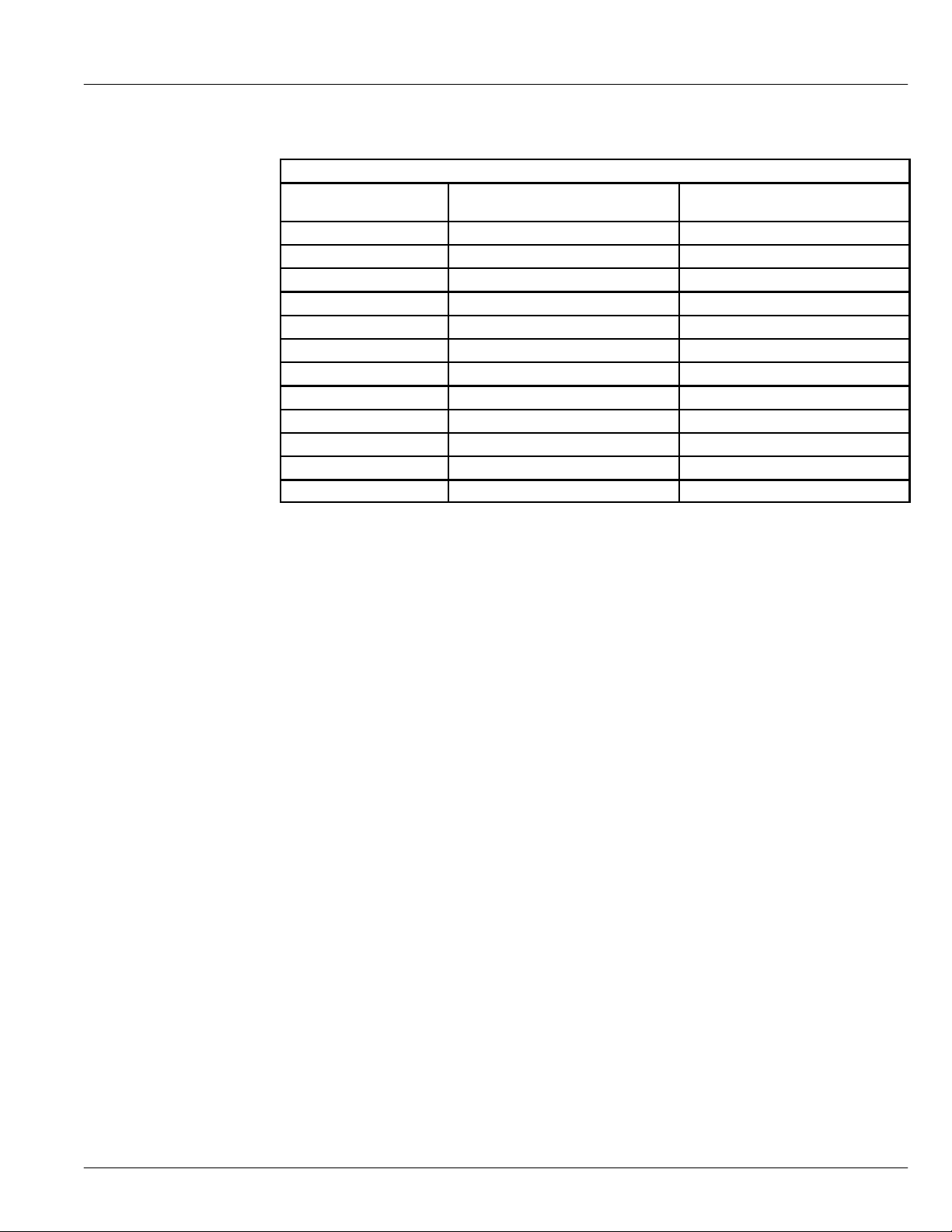
Factor into your diet the amount of sodium or potassium shown below, based on your water
hardness and consumption.
Sodium Added to Water from Cation Exchange Softening
Initial Water Hardness
Grains per Gallon Milligrams Na+/qt. Milligrams K+/qt.
1 7.5 12.75
5 37 62.9
6 44 74.8
7 52 88.4
8 60 102
9 68 115.6
10 75 127.5
15 112 190.4
20 150 255
30 225 382.5
40 300 510
Sodium added by Cation
Exchange Softening of Water*
Potassium added by Cation
Exchange Softening of Water**
*If your water supply is 15 grains hard and you drank 3 quarts of softened water you would
consume 335 milligrams of sodium. That is equivalent to eating 2--1/2 slices of white bread.
**One large banana, about 9 inches in length, has approximately 600 milligrams of potassium.
2. Iron in water can cause stains on clothing and plumbing fixtures. It can negatively affect the taste
of food, drinking water, and other beverages. Iron in water is measured in parts per million (ppm).
The total*ppm ofiron, and type or types*, is determined bychemical analysis. Four different types
of iron in water are:
Ferrous (clear water),
Ferric (red water),
Bacterial and organically bound iron,
Colloidal and inorganically bound iron (ferr ous or ferric).
*Water may contain one or more of the four types of iron and any combination of these. Total iron
is the sum of the contents.
Ferrous (clear water) iron is soluble and dissolves in water. This water softener will remove
moderate amounts of this type of iron (see specifica tions). Ferrous (clear water) iron is usually
detected bytaking a sample of water in a clear bottle or glass. Immediately after taking, the sample
is clear. As the water sample stands, it gradually clouds and turns slightly yellow or brown as air
oxidizes the iron. This usually occurs in 15 to 30 minutes.
When using the softener to remove Ferrous (clear water) iron, add 5 grains to the hardness setting
for every 1 ppm of Ferrous (clear water) iron.
7
Page 8

Ferric (red water), and bac terial andorganically boundirons are insoluble. Thiswater softener will
not remove ferric or bacterial iron. This iron is visible immediately when drawn from a faucet
because it has oxidized before reaching the home. It appears as small cloudy yellow, orange, or
reddish suspended particles. After the water stands for a period of time, the particles settle to the
bottom of the container. Generally these irons are removed from water by filtration. Chlorination
is also recommended for bacterial iron.
Colloidal and inorganically bound iron is of ferric or ferrous form that will not filter or exchange
out of water. This water softener will not remove colloidal iron. In some instances, treatment may
improve colloidal iron water. Colloidal iron water usually has a yellow appearance when drawn.
After standing for several hours, the color persists and the iron does not settle, but remains
suspended in the water.
3. Acidity or acid water is caused by carbon dioxide and hydrogen sulfide. This water softener will
not improve an acid condition in water. Acid water can be corrosive to plumbing, plumbing
fixtures, water heaters, andother waterusing appliances. In can alsodamage andcause premature
failure of seals, diaphragms, etc., in water handling equipment.
A chemical analysis is needed to measure the degree of acidity in water. This is called the pH of
water. Water testing below 6.9 pH is acidic. The lower the pH reading, the greater the acidity. A
neutralizer filter or a chemical feed pump are usually recommended to treat acid water.
4. Sediment is fine, foreign material particles suspended in water. This water softener will not
remove sediment. This material is most often clay or silt. Extreme amounts of sediment may give
the water a cloudy appearance. A sediment filter installed ahead of the water softener normally
corrects this situation.
Installation Requirements
Tools and Parts Needed
Assemble the required tools before starting installation. Read andfollow the instructions provided with
any tools listed here.
• Screwdriver • Tape Measure
• Pliers
If using Soldered Copper Pipe
• Tubing cutter • Lead--free solder and flux
• Propane torch • Emery cloth, sandpaper or steel wool
• Misc. copper pipe fittings
If using Threaded Pipe
• Pipe cutter or hacksaw • Pipe joint compound
• Threading tool • Misc. threaded pipe fittings
If using CPVC Plastic
• Pipe cutter • Solvent cement
• Hacksaw • Primer
• Adjustable wrench • Misc. CPVC pipe fittings
If using Other
• Other pipe and fittings suitable for potable water supply as required by piping system
manufacturer and loc al codes and/or ordinances.
8
Page 9

Location Requirements
Consider all of the following when selecting an installation location for the water softener.
• Do not locate the water softener where freezing temperatures occur. Do not attempt to
treat water over 120_F. Freezing, or hot water damage voids the warranty.
• To condition all water in the home, install the water softener close to the water supply
inlet, and before all other plumbing connections, except outside water pipes. Outside
faucets should remain on hard water to avoid wasting conditioned water and salt.
• A nearby drain is needed to carry away regeneration discharge (drain) water. Use a floor
drain, laundry tub, sump, standpipe, or other options (check your local codes). See “Air
Gap Requirements” and “Valve Drain Requirements” sections.
• The water softener works on 24 volt--60 hz electrical power only, supplied by a direct
plug--in transformer (included). Provide an electrical outletin accordance with NECand
local codes.
• Always install the water softener between the water heater and water inlet. Any other
installed water conditioning equipment should be installed between the water softener
and the water inlet (see Figure 1 below).
city water supply
water heater
water softener
Figure 1
Air Gap Requirements
A drain is needed for regeneration discharge water. A floor drain, close to the water softener, is
preferred. A laundry tub, standpipe, etc., are other dra in options. Secure valve drain hose in place.
1---1/2”
airgap
cold to
drain
hose
optional
sediment
filter
drain
hose
pressure tank
well pump
OR
well water supply
drain
hose
Figure 2
standpipe
1---1/2”
airgap
1---1/2”
airgap
laundry tubfloor drain
9
Page 10

Valve Drain Requirements
Use the flexible drain hose, that is included, measure and cut to the length needed. Flexible drain hose
is notallowed inall localities (check your plumbingcodes). If local codes do not allow use of aflexible
drain hose, a rigid valve drain run must be used. Buy a compression fitting (1/4 NPT x 1/2 in. minimum
tube) and 1/2” tubing from your local hardware store. Then plumb a rigid drain as needed (see Figure
3).
NOTE: Avoid long drain hose runs, or elevating the hose more than 8’ above the floor. Make the
water softener valve drain as short and direct as possible.
1/4” NPT thread
Barbs for 3/8” I.D. tubing
Hose clamp
Drain hose
Clip
Cut barbs from valve drain elbow (pull clip
and remove drain valve elbow from valve)
1/4” NPT thread
Figure 3
barbs
Compression fitting 1/4 NPT x
1/2” O.D. tube (not provided)
1/2” outside diameter copper
tube (not provided)
10
Page 11
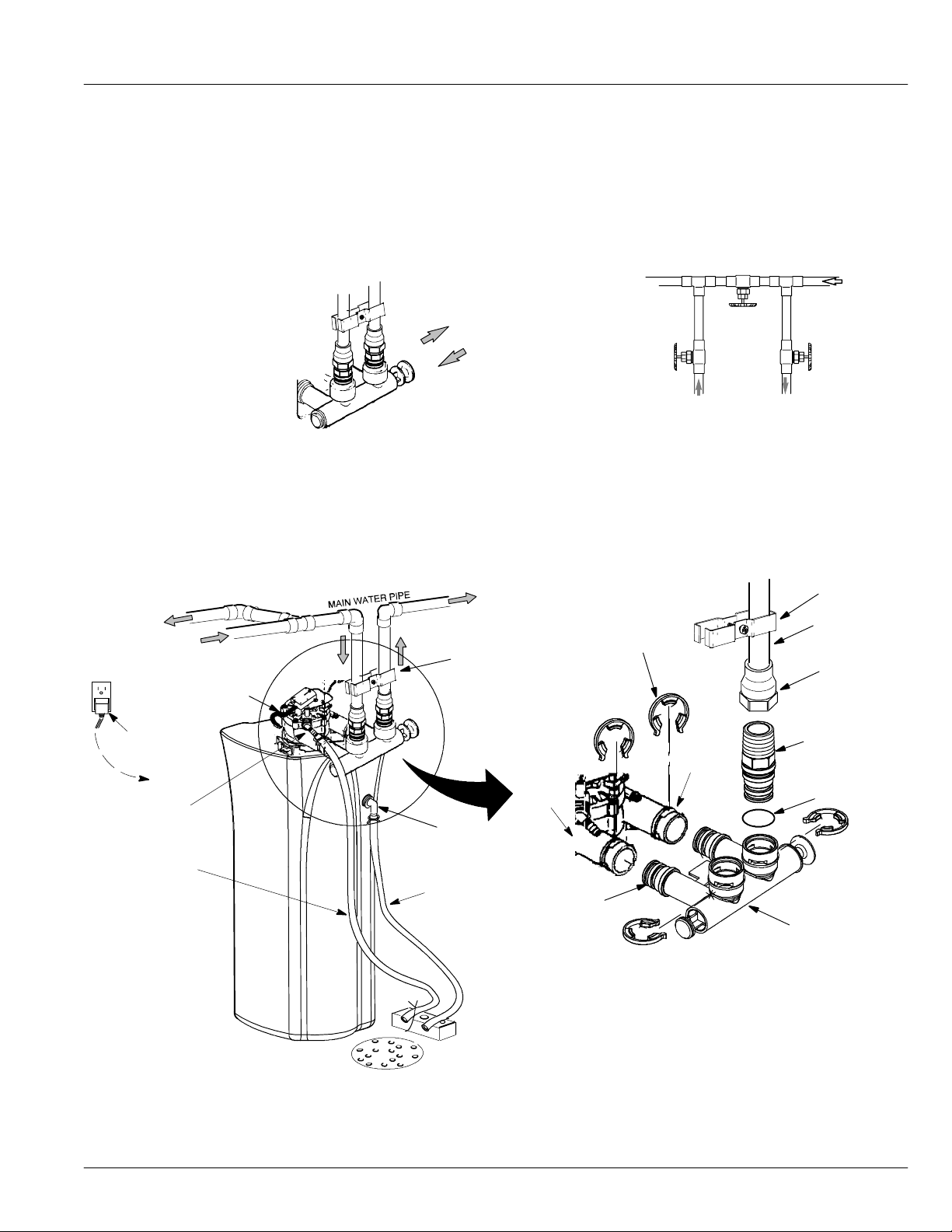
Plan the Installation
Inlet --- Outlet Plumbing Options
Always install either a single bypass valve (provided) or, if desired, parts for a 3 valve bypass system
(not included) can be purchased and assembled, as shown in Figure 4. Bypass valves allow you to turn
off water to the softener for maintenance if needed, but still have water in house pipes.
Single valve bypass
pull out for
service/ soft water
push in
for bypass
outlet
valve
3 valve bypass
bypass
valve
inlet
valve
to outside
faucets
hard water
water softener valve
direct plug--- in
transformer
to timer
valve drain
elbow
valve drain
hose *
* Do not connect
the water softener
valve drain tubing
to the salt storage
tank overflow
hose.
from water softener
to water softener
Figure 4
• Pipe and fittings must be 3/4” minimum.
Use either:
• Copper pipe • Threaded pipe
• CPVC plastic pipe • Other pipe approved for use with potable water
conditioned
water
grounding clamp
overflow drain
elbow
salt storage tank
overflow hose *
To keep over floor drain, secure
valve drain hose in place.
clips
outlet
inlet
lubricated
o---ring
grounding
clamp
3/4” pipe
1” NPT sweat
adaptor (not
included)
1” NPT
threaded
adaptor
o---ring
single valve
bypass
NOTE: See “Air Gap Requirements” section.
floor drain
NOTE: Shown with salt hole cover and top cover removed.
Figure 5 (typical installation)
11
Page 12
Installation
Turn Off Water Supply
1. Close the main water supply valve, near the well pump or water meter.
2. Open all faucets to drain all water from the house pipes.
NOTE: Be sure not to drain water from the water heater, as damage to the water heater
elements could result.
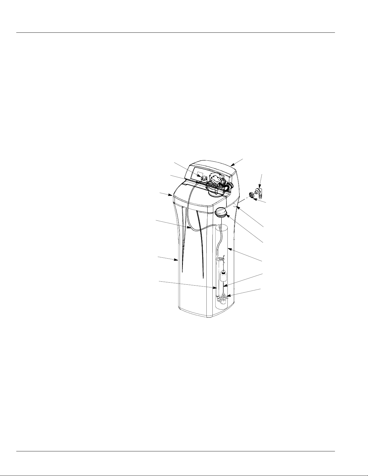
Install the Brine Tank Overflow Elbow
Install the brine tank overflow grommet and elbow in the 13/16” diameter hole in the back of the salt
storage tank sidewall.
NOTE: The salt storage tank drain elbow accepts either 1/2” or 3/8” I. D. hose.
Nozzle venturi assembly
Nut ---ferrule
Salt hole cover
Brine tubing
Top c o v e r
Brine tank overflow elbow
Brine tank overflow
grommet
13/16” hole
Salt storage tank
Stand tube
Brinewell cover
Brinewell
Float stem
Brine valve
Figure 6
12
Page 13
Move the Water Softener into Place
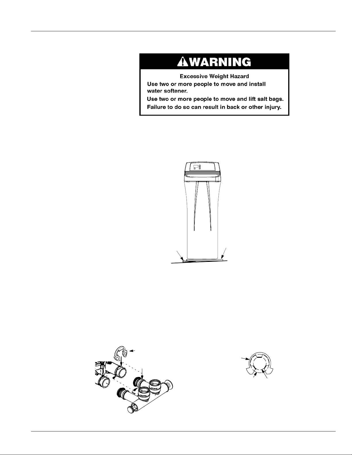
1. Move the water softener into installation position. Set it on a level surface. If needed, place the
water softener on a section of plywood, a minimum of 3/4” thick. Then, shim under the plywood
to level the water softener, see Figure 7.
IMPORTANT: Do not place shims directly under the salt storage tank. The weight of the tank, when
full of water and salt, may cause the tank to fracture at the shim.
Shim
Plywood
Figure 7 (if needed for leveling)
2. Visually check and remove any debris from the wa ter softener valve inlet and outlet ports.
3. Remove and discard the yellow plug and make sure the turbine assembly spins freely in the “out”
port of the va lve.
4. If not already done, put a light coating of silicone grease or petroleum jelly on the bypass valve
o-rings.
5. Push the bypass valve into the softener valve as far as it will go. Snap the two large holding clips
into place, from the top down as shown in Figure 8.
IMPORTANT: Be sure the clips snap firmly into place so the single valve bypass will not pull out.
clip
channel
outside diameter of water
softener valve inlet and outlet
NOTE: Be sure all 3 tabs of the clip go through the matching holes
on the water softener valve inlet or outlet, and fully into the channel
onthesinglevalvebypass.
correct assembly
clip
outside diameter of clip channel on single valve bypass
Figure 8
13
Page 14
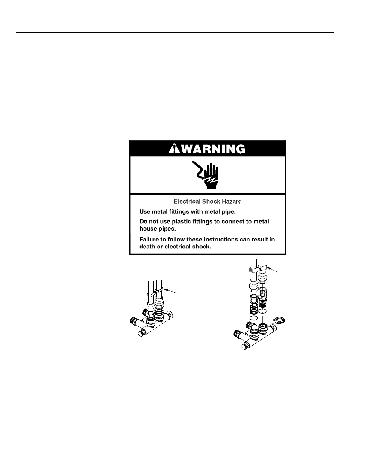
Assemble Inlet and Outlet Plumbing
Measure, cut, and loosely assemble pipe and fittings from the main water pipe to the inlet and outlet
ports of the water softener valve. Be sure to keep fittings fully together, and pipes squared and straight.
Be sure hard water supply pipe goes to the water softener valve inlet side.
NOTE: Inlet and outlet are marked on the valve. Trace the water flow direction to be sure.
IMPORTANT: Be sure to fit, align and support all plumbing to prevent putting stress on the softener
valve inlet and outlet. Undue stress from misaligned or unsupported plumbing may
cause damage to the valve.
Connect Inlet and Outlet Plumbing
Complete the inlet and outlet plumbing for the type of pipe as shown below.
Soldered copper
1. Thoroughly clean and apply solder flux to all joints.
2. Make all solder connections.
NOTE: Do not solder with plumbing attached to installation adaptors and single valve bypass.
IMPORTANT: Secure ground clamp to metal pipes.
Ground Clamp
Ground Clamp
Figure 9
Soldering heat will damage the adaptors and valve.
14
Page 15

Threaded pipe
1. Apply pipe joint compound or TeflonRtape to all male pipe threads.
2. Tighten all threaded joints and make all solder connections.
IMPORTANT: Secure ground clamp to metal pipes.
CPVC plastic pipe
1. Clean, prime and cement all joints, following the manufacturer’s instructions supplied with the
plastic pipe and fittings.
Other
1. Follow the piping system manufacturer’s instructions when using other pipe approved for potable
water.
IMPORTANT: Secure ground clamp to metal pipes.
Install Valve Drain Hose
1. Measure, cut to needed length and connect the 3/8” drain line (provided) to the water softener
valve drain fitting. Use a hose clamp to hold the hose in place.
NOTE: If codes require a rigid drain line see “Valve Drain requirements” section.
2. Run the drain hose or copper tubing to the floor drain. Secure drain hose. This will prevent
‘‘whipping’’ during regenerations. See “Air Gap Requirements” section.
Install Salt Storage Tank Overflow Hose
Te st f o r L e a ks
1. Measure, cut to needed length and connect the 3/8” drain line (provided) to the salt storage tank
overflow elbow and secure in place with a hose clamp.
2. Run the hose to the floor drain, or other suitable drain point no higher than the drain fitting on the
salt storage tank. (This is a gravity drain.) If the tank overfills with water, the excess water flows
to the drain point. Cut the drain line to the desired length and route neatly out of the way.
IMPORTANT: For proper operation of the water softener, do not connect the water softener
valve drain tubing to the salt storage tank overflow hose.
To prevent air pressure in the water softener and plumbing system, do the following steps in order.
1. Fully open two or more softened cold water faucets close by the water softener, located
downstream from the water sof tener.
2. Place the single valve bypass valve or 3 valve bypass in “bypass” position. See “Plan The
Installation” section.
3. Fully open the main water supply valve. Run water until there is a steady flow from the opened
faucets, with no air bubbles.
4. Place bypass valve(s) in “service” or soft water position as follows:
• Single valve bypass: Slowly movethe valve stem toward “service”, pausing several times
to allow the water softener to fill with water.
• 3 valve bypass: Fully close the bypass valve and open the outlet valve. Slowly open the
inlet valve, pausing several times to allow the water softener to fill with water.
5. After about three minutes, open a hot water faucet until there is a steady flow and there are no air
bubbles, then close.
6. Close all cold water faucets and check for leaks at the plumbing connections that you made.
15
Page 16

Add Water and Salt to the Salt Storage Tank
1. Using a container, add about three gal lons of clean water into the salt storage tank.
2. Add salt to the storage tank. Use nugget, pellet or coarse solar salts with less than 1% impurities.
NOTE: See “Routine Maintenance Section” for additional information on salt.
Persons who are on sodium restricted diets should consider the added sodium as part of their overall sodium intake.
For example, if your water supply is 15 grains hard, and you drank 3 quarts of softened water you would consume
335 milligrams of sodium. That is equivalent to eating 2--1/2 slices of white bread.
NOTE: The salt monitor system is calibrated to the density of nugget or pellet water softener salt. The monitor
will not work as accurately with other types of salt including rock and solar.
If you choose Potassium Chloride (KCl) as a re generant, following these suggestions will help give you years of
maintenance free service.
1. Place only one bag of KCl in your softener at a time (the salt storage tank should contain no more than 60
pounds of KCl at any one time).
2. A softener using KCl should not be placed in areas with temperature fluctuations and high humidity (KCl will
harden in these environments and may make the softener inoperable).
3. Check the brine tank and brine well (black tube in salt storage tank) monthly. If hardening is present, poursmall
amounts of warm water on hardened areas until they loosen.
4. If your softener does not have a KCl salt setting you must increase your hardness setting by 25% to ensure
continuous soft water as in example below.
Raw Water Hardness Softener Setting Raw Water Hardness Softener Setting
(Grains per Gallon) When Using KCl (Grains per Gallon) When Using KCl
5gpg +25%= 7gpg 25gpg +25%= 32gpg
10 gpg 13 gpg 30 gpg 38 gpg
15 gpg 19 gpg 35 gpg 44 gpg
20 gpg 25 gpg 40 gpg 50 gpg
Sanitize the Softener/Sanitize After Service
1. Open salt hole cover and remove the brinewell cover a nd pour about 1--1/2 oz. (2 to 3tablespoons) of household
bleach into the softener brinewell. Replace the brinewell cover.
2. Make sure the bypass valve(s) is in the service (open) position.
3. Sanitize procedure will be completed when first cycle is run and sanitizing solution is flushed from the water
softener.
Plug in Water Softener
During installation, the water softener wiring may be moved or jostled from place. Check to be sure all leadwire
connectors aresecure on the back ofthe electronic board a nd be sure all wiring isaway from the valve gear and motor
area, which rotates during regenerations.
1. Plug the water softener into an electrical outlet that is not controlled by a switch.
NOTE:
16
The water heater is filled with hard water and, as hot water is used, it refills with conditioned water. In afew days, the
hot water will be fully conditioned. To have fully conditioned hot water immediately, wait until the initial recharge
is over. Then, drain the water heater (following instructions for water heater) until water runs cold.
Page 17
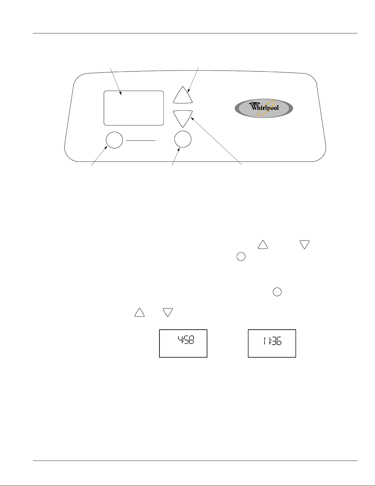
Program the Water Softener -- Model WHES20
Display
RECHARGE button
Figure 10
If you have questions about installation, programming, operating and routine maintenance...
When the transformer is plugged into the e lectrical outlet, a model code and a test number (example:
s3.0), begin to flash in the faceplate display. Then, 12:00 PM and the words“PRESENT TIME” begin
to flash.
UP button
+
−
PRESS TO SCHEDUL E
HOLD TO ST ART
RECHARGE
PROGRAM button
PROGRAM
DOWN Button
call 1--866--986--3223, Monday -- Friday, 8 am to 9 pm, EST.
NOTE: If -- -- -- -- shows in the display, press the UP
shows in the display. Then, press the
flashing “PRESENT TIME” display.
+
or DOWN
−
button until LE20
PROGRAM button to set, and change to the
Set Time of Day
If the words “PRESENT TIME” do not show in the display, press the PROGRAM button until they
do.
−
Down buttons to set the present time. Up moves the display ahead; down
1. Press the
+
Up or
sets the time back.
PRESENT TIME
PM
PRESENT TIME
AM
Be sure AM or PM is correct.
NOTE: Press buttons and quickly release to slowly advance the display. Hold the buttons
down for fast advance. This procedure applies for all following settings.
17
Page 18
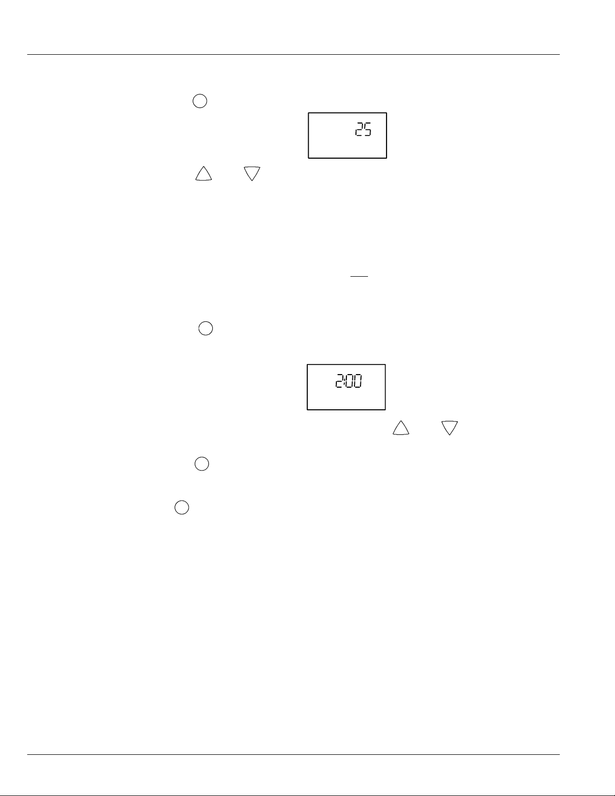
Set Water Hardness Number
1. Press the PROGRAM buttononce again to display a flashing 25 and the word “HARDNESS”.
HARDNESS
2. Press the
+
Up or
NOTE: Be sure to enter the grains per gallon (gpg) hardness of your water supply on page 5, for
future reference. If your water supply contains iron, compensate for it by adding to the
water hardness number. For example, assume your water is 20 gpg hard and contains 2
ppm iron. Add 5 to the hardness number for each 1 ppm of iron. In this example, you
would use 30 for your hardness number.
2 ppm iron x 5 = 10 +10
Set Recharge (Regeneration) Time
1. Press the PROGRAM button once again to display a flashing 2:00AM and the words
“RECHARGE TIME”. This is a good time for the recharge to start in most households because
water is not in use.
If you want to change the recharge start time, press the
desired starting time shows.
−
Down buttons to set your wate r hardness number.
20 gpg hardness
(times) 30 HARDNESS NUMBER
AM
RECHARGE
TIME
+
Up or
−
Down buttons until the
Start a Recharge
2. Press the
PROGRAM button once again to return to normal operating display.
Press the RECHARGE button and hold for three seconds untilthe word “Recharge” begins to flash
in the timer display, starting a recharge. This recharge draws the sanitizing bleach into and through the
water softener. Any air remaining in the water softener is purged to the drain.
If you have questions aboutinstallation, electronic programming, operating and routine maintenance...
call 1--866--986--3223, Monday -- Friday, 8 am to 9 pm, EST.
18
Page 19
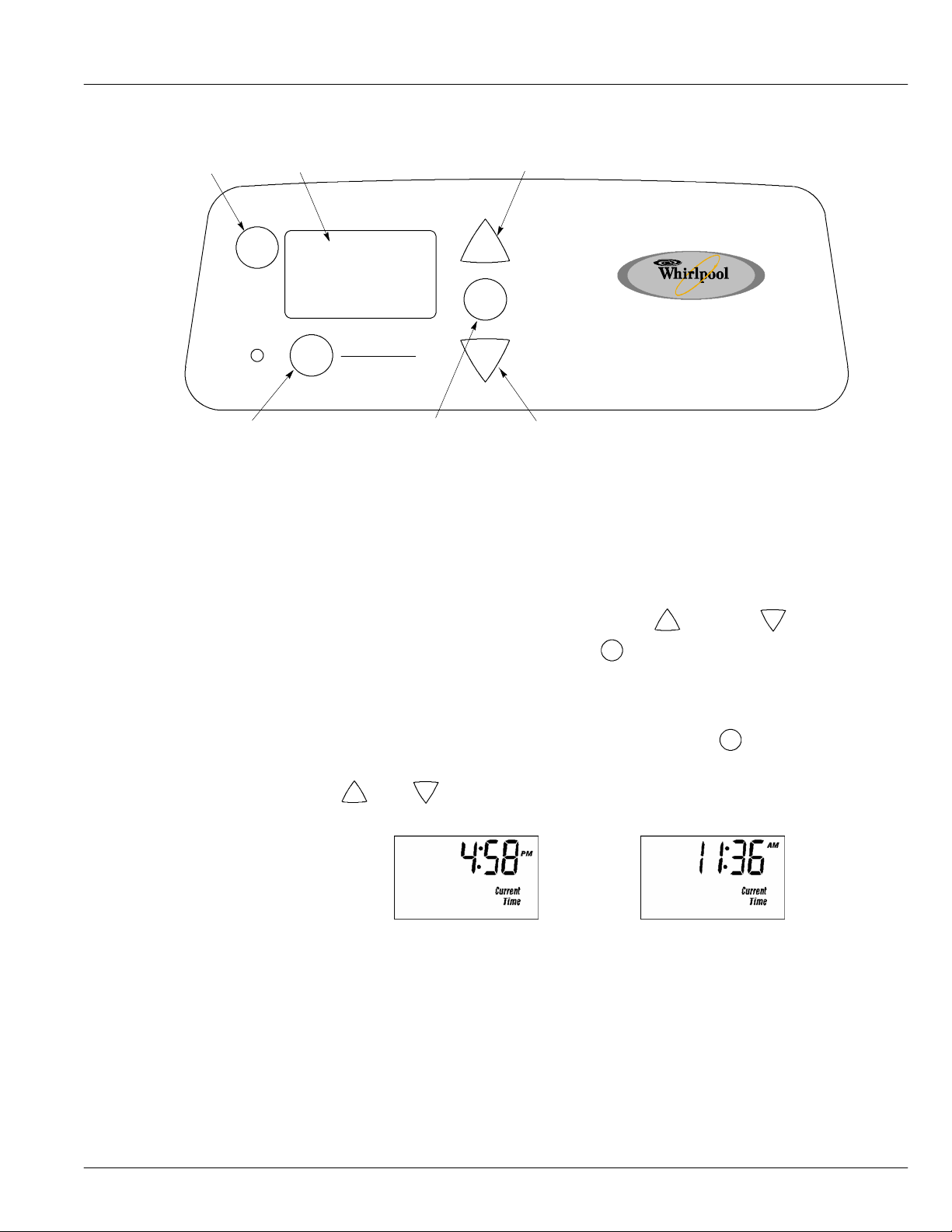
Program the Water Softener -- Model WHES30
SETSALTLEVELbutton
SET
SALT
LEVEL
CHECK
SALT
LEVEL
RECHARGE button
Figure 11
If you have questions about installation, programming, operating and routine maintenance...
When the transformer is plugged into the e lectrical outlet, a model code and a test number (example:
s3.0), begin to flash in the faceplate display. Then, 12:00 PM and the words “CURRENTTIME” begin
to flash.
Display
UP button
+
PROGRAM
PRESS TO SCHEDUL E
HOLD TO ST ART
RECHARGE
PROGRAM button
−
DOWN Button
call 1--866--986--3223, Monday -- Friday, 8 am to 9 pm, EST.
NOTE: If -- -- -- -- shows in the display, press the UP
shows in the display. Then, press the
PROGRAM button to set, and change to the
flashing CURRENT TIME display.
+
or DOWN
−
button until LE31
Set Time of Day
If the words “CURRENT TIME” do not show in the display, press the PROGRAM button until
they do.
−
Down buttons to set the present time. Up moves the display ahead; down
1. Press the
+
Up or
sets the time back.
Be sure AM or PM is correct.
NOTE: Press buttons and quickly release to slowly advance the display. Hold for fast
advance. This procedure applies for all following settings.
19
Page 20
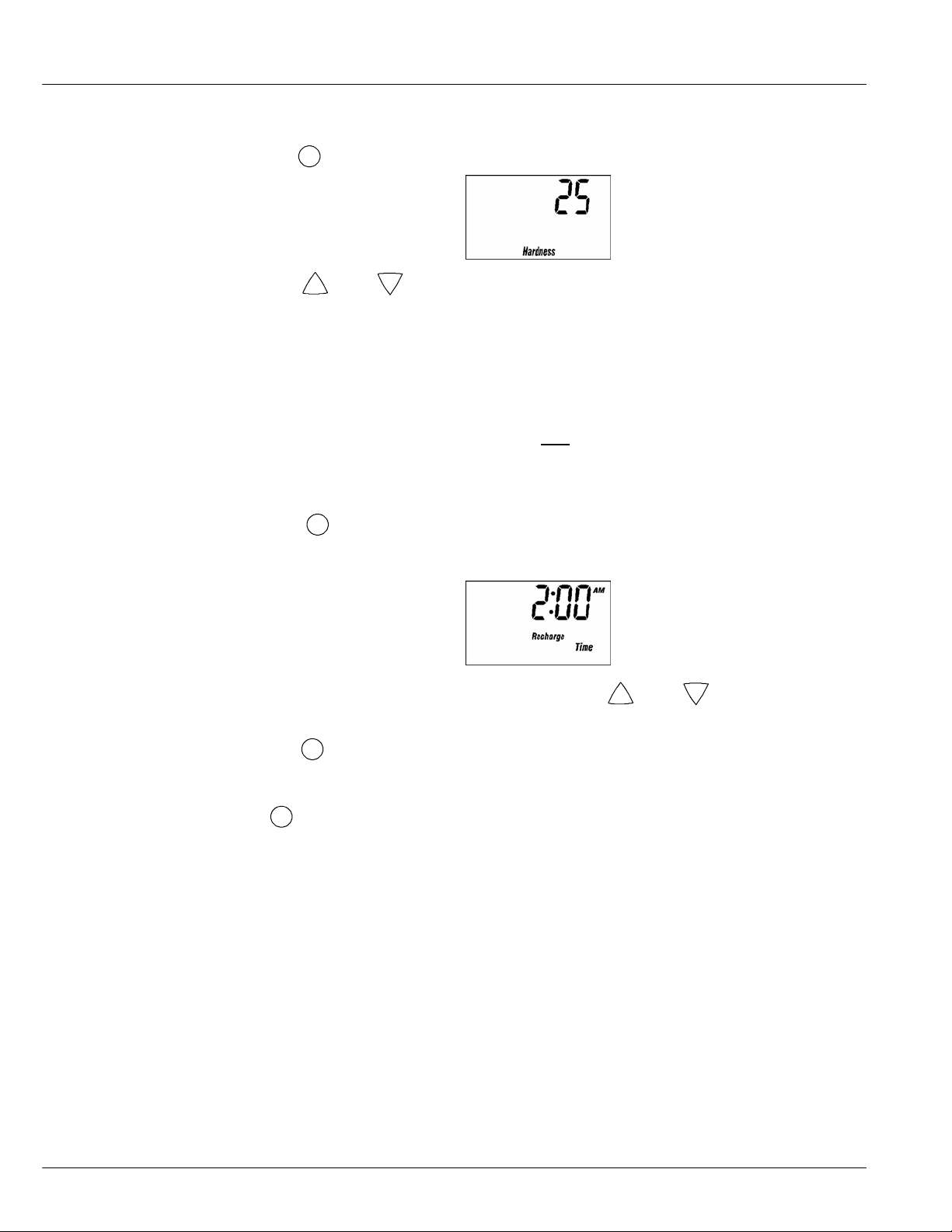
Set Water Hardness Number
1. Press the PROGRAM buttononce again to display a flashing 25 and the word “HARDNESS”.
2. Press the
NOTE: Be sure to enter the grains per gallon (gpg) hardness of your water supply on page 5, for
+
Up or
future reference. If your water supply contains iron, compensate for it by adding to the
water hardness number. For example, assume your water is 20 gpg hard and contains 2
ppm iron. Add 5 to the hardness number for each 1 ppm of iron. In this example, you
would use 30 for your hardness number.
2 ppm iron x 5 = 10 +10
Set Recharge (Regeneration) Time
1. Press the PROGRAM button once again to display a flashing 2:00AM and the words
“RECHARGE TIME”. This is a good time for the recharge to start in most households because
water is not in use.
If you want to change the recharge start time, press the
desired starting time shows.
−
Down buttons to set your wate r hardness number.
20 gpg hardness
(times) 30 HARDNESS NUMBER
+
Up or
−
Down buttons until the
Start a Recharge
20
2. Press the
PROGRAM button once again to return to normal operating display.
Press the RECHARGE button and hold for three seconds untilthe word “Recharge” begins to flash
in the timer display, starting a recharge. This recharge draws the sanitizing bleach into and through the
water softener. Any air remaining in the water softener is purged to the drain.
If you have questions aboutinstallation, electronic programming, operating and routine maintenance...
call 1--866--986--3223, Monday -- Friday, 8 am to 9 pm, EST.
Page 21
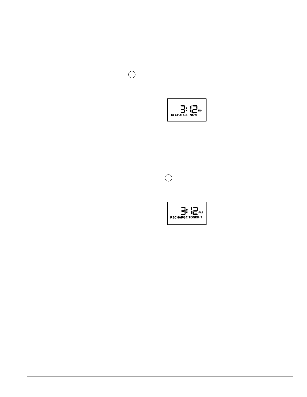
Recharge
Customizing Features/Options -- Model WHES20
Recharge button is used to initiate an immediate recharge.
Recharge Tonight
• Press and hold the
in the display, and the softener enters the fill cycle of regeneration right away.
“RECHARGE NOW” will flash during the regener ation. When over, full water
conditioning capacity is restored.
NOTE: Avoidusing hot waterwhile the conditioneris regenerating, because the water heater will
refill with bypass hard water.
If you do not want to start an immediate recharge, but would like an extra recharge at the next preset
recharge time, do the following to schedule a recharge.
• Press and release (do not hold) the
TONIGHT” flashes inthe display,and the softener willrecharge at the next recharge time.
“RECHARGE NOW” will flash during the regener ation. When over, full water
conditioning capacity is restored.
RECHARGEbutton until the words “RECHARGE NOW” flashes
RECHARGE NOW Initiated
RECHARGE button. The words “RECHARGE
‘‘Power---Outage Memory’’
If electrical power to the water softener is lost, ‘‘memory’’ built into the timer circuitry will keep all
settings for up to eight hours. While the power is out, the display is blank and the water sof tener will
not regenerate. When electrical power is restored, the following will occur.
1. You have to reset the present time only if the display is flashing. The HARDNESS and
RECHARGE TIME never require resetting unless a change is desired. Even if the clock is
incorrect after a long pow er outage, the softener works as it should to keep your water soft.
However, regenerations may occur at the wrong time ofday until you reset the clock to the correct
time of day.
NOTE: If the water softener was regenerating when power was lost, it will now finish the cycle.
RECHARGE TONIGHT Initiated
21
Page 22
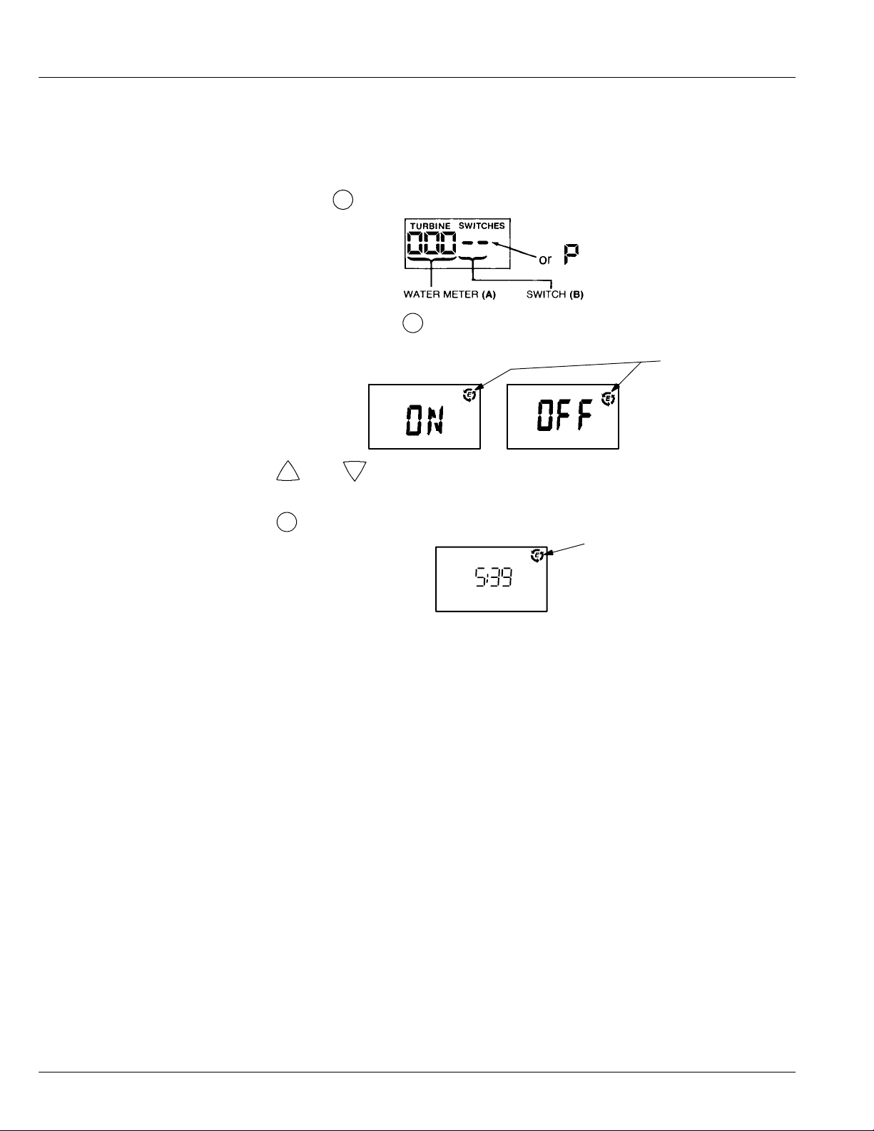
Salt Efficiency
When this feature is ON, the water softener will operate at salt efficiencies of 4000 grains of hardness
per pound of salt or higher. (May recharge more often using smaller salt dosage and less water). The
softener is shipped in the OFF setting.
1. Press and hold the
PROGRAM button until the following screen is displayed.
Once in this display, press the PROGRAM button and one of the following two displays is
shown.
Efficiency Icon
−
Down buttons to set On or Off. When set to On, the efficiency icon will
2. Press the
+
Up or
be displayed in the upper right hand corner of the normal run display.
3. Press the
PROGRAM button once again, to return to normal run display.
Displayed when
PM
RECHARGE T ONIGHT
efficiency is set to “On”
22
If you have questions about installation, programming, operating and routine maintenance...
call 1--866--986--3223, Monday -- Friday, 8 am to 9 pm, EST.
Page 23
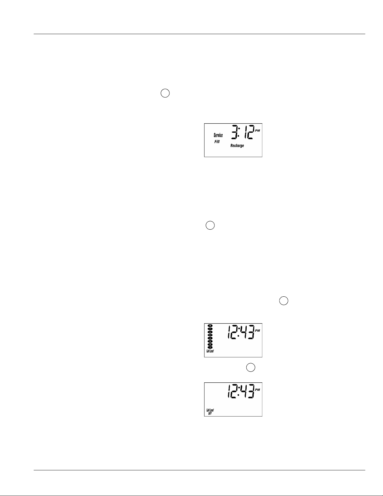
Recharge
Customizing Features/Options-- Model WHES30
Recharge button is used to initiate an immediate recharge.
• Press and hold the
and “FILL” flash in the display, andthe softenerenters the fill cycle of regeneration right
away.The word “RECHARGE” will flashduring the regeneration. When over, full water
conditioning capacity is restored.
NOTE: Avoidusing hot waterwhile the conditioneris regenerating, because the water heater will
Recharge Scheduled
If you do not want to start an immediate recharge, but would like an extra recharge at the next preset
recharge time, do the following to schedule a recharge.
• Press and release (do not hold) the
SCHEDULED” flashes in the display, and the softener will recharge at the next recharge
time. The word “RECHARGE” will flash during the regeneration. When over, full water
conditioning capacity is restored.
SetSaltLevel
The water softener has a salt monitor indicator light to remind you to refill the storage tank with salt.
• To set this monitor system, lift the salt hole cover and level the salt in the storage tank.
The salt level decal, on the brinewell inside the tank, has numbers from 0 to 8. Observe
the number the leveled salt is at, or closest to. Now, press the
button until black ovals corespond to the salt level number. At level 2 or below, the
indicator LED will flash “Check Salt Level”.
RECHARGE button until the words “RECHARGE”, “SERVICE”
RECHARGE NOW Initiated
refill with bypass hard water.
RECHARGE button. The words “RECHARGE
SET SALT LEVEL
• If you want to turn the salt monitor off, press the SET SALT LEVEL button until
“SALT LEVEL OFF” shows in display.
23
Page 24
‘‘Power---Outage Memory’’
If electrical power to the water softener is lost, ‘‘memory’’ built into the timer circuitry will keep all
settings for up to eight hours. While the power is out, the display is blank and the water sof tener will
not regenerate. When electrical power is restored, the following will occur.
1. You have to reset the present time only if the display is flashing. The HARDNESS and
RECHARGE TIME never require resetting unless a change is desired. Even if the clock is
incorrect after a long pow er outage, the softener works as it should to keep your water soft.
However, regenerations may occur at the wrong time ofday until you reset the clock to the correct
time of day.
NOTE: If the water softener was regenerating when power was lost, it will now finish the cycle.
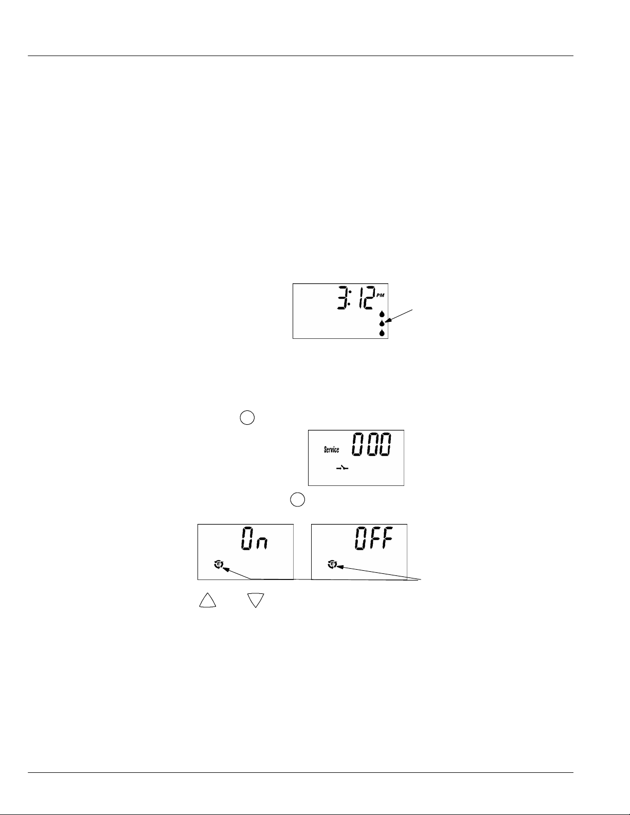
Water Flow Indicator
Whenever the softener has water flowing from the outlet port, the display will show water droplets
scrolling down the right hand side of the screen. The faster the water flow, the faster the droplets will
flash.
Salt Efficiency
When this feature is ON, the water softener will operate at salt efficiencies of 4000 grains of hardness
per pound of salt or higher. (May recharge more often using smaller salt dosage and less water). The
softener is shipped in the OFF setting.
Droplets indicate water
flow through softener
1. Press and hold the
PROGRAM button until the following screen is displayed.
Once in this display, press the PROGRAM button and one of the following two displays is
shown.
Efficiency Icon
−
Down buttons to set On or Off. When set to On, the efficiency icon will
2. Press the
+
Up or
be displayed in the lower left hand corner of the normal run display.
24
Page 25
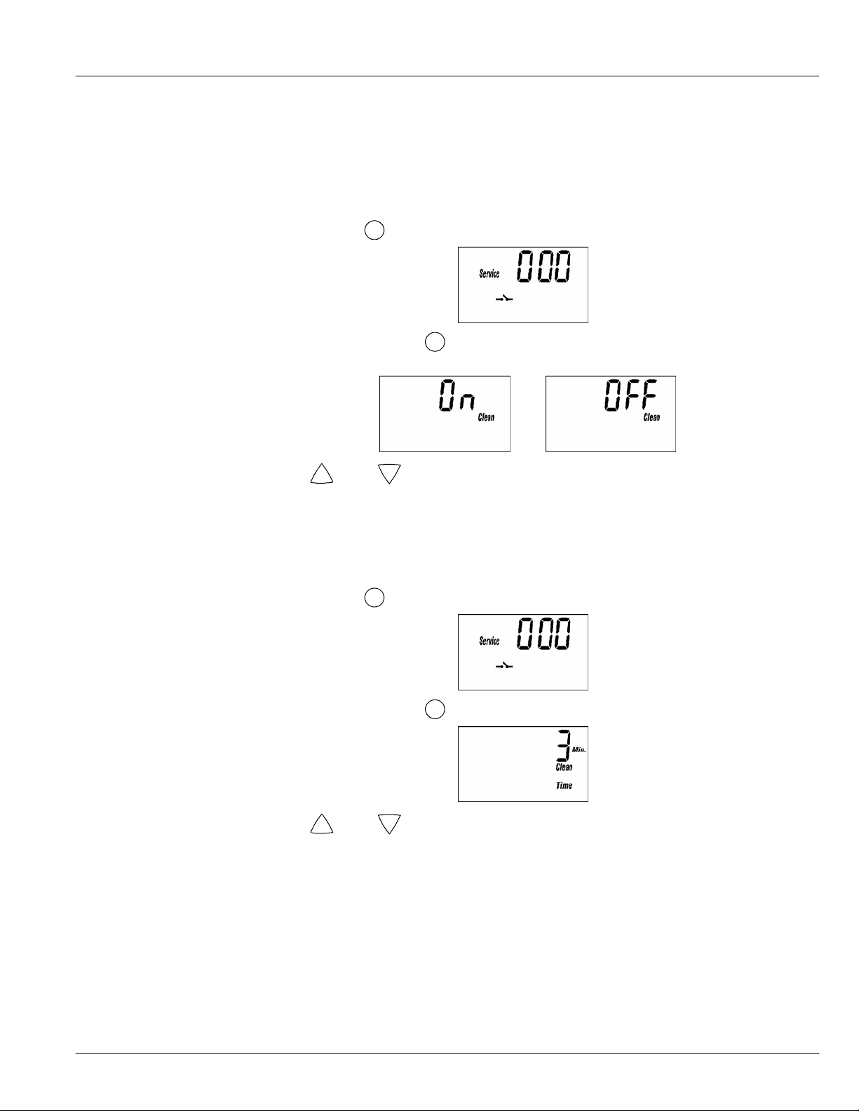
Clean / Clear Water Iron Removal
This feature is beneficial on water supplies containing iron and/or high amounts of sediments (sand,
silt, dirt, etc.). When set to “ON”, an additional backwash and fast rinse cycle will occur first,
preceeding the normal regeneration sequence. This provides extra cleaning of the resin bed before it
is regenerated with the salt brine. To conserve water set this feature “OFF” if your water supply does
not contain iron or sediments.
1. Press and hold the
Once in this display, press the PROGRAMbutton twice andone of the following two displays
is shown. Both displays will show the word “Clean”.
2. Press the
Clean Feature Minutes
Adjust the length of the Clean/Clear Water Iron Removal feature, from 1 to 15 minutes in length. To
change this cycle time, use the UP button to increase the time, or the DOWN button toshorten the time.
If you are using this feature the length of the extra backwash cycle automatically sets to 3 minutes.
1. Press and hold the
+
Up or
PROGRAM button until the following screen is displayed.
−
Down buttons to set On or Off.
PROGRAM button until the following screen is displayed.
Once in this display, press the PROGRAMbutton three times and following display is shown.
−
Down buttons to set number of minutes.
2. Press the
+
Up or
25
Page 26

Maximum Days Between Regenerations
The water softener automatically controlsregeneration frequency.This providesthe greatest operating
efficiency, and under most conditions, this feature should be left in this mode. However, modify this
feature if youwant to force a regeneration every setnumber of days. For example, if your water supply
contains iron and you want the softener to regenerate at least once every few days to keep the resin
bed clean, set the display as shown below. Setting is available from 1 to 15 days by using the UP and
DOWN buttons.
NOTE: The softener willrecharge on its own if needed, even if it is before the setnumber of days.
1. Press and hold the
2. Press the
12 or 24 Hour Clock
All time displays are shown in standard clock time (1 to 12 PM; and 1 to 12 AM) at the 12 hr default
setting. If 24 hour clock displays are desired, follow steps below.
1. Press and hold the
PROGRAM button until the following screen is displayed.
Once in this display, press the PROGRAM button four times and following display is shown.
+
Up or
−
Down buttons to set number of days.
PROGRAM button until the following screen is displayed.
26
Once in this display, press the PROGRAM button five times and the following display is
shown.
12 Hour Clock Initiated 24 Hour Clock Initiated
−
Down buttons to set clock.
2. Press the
+
Up or
If you have questions about installation, programming, operating and routine maintenance...
call 1--866--986--3223, Monday -- Friday, 8 am to 9 pm, EST.
Page 27
Routine Maintenance
Refilling With Salt
Lift the salt hole cover and check the salt storage level frequently. If the conditioner uses all the salt
before you refill it, you will get hard water. Until you have established a refilling routine, check the
salt every two or three weeks. Always add if less than 1/4 full. Be sure the brinewell cover is on.
NOTE: In humid areas, it is best to keep the salt storage level lower, and to refill more often to
Recommended Salt: Nugget, pellet or coarse solar salts with less than 1% impurities.
Salt Not Recommended: Rock salt, high in impurities, block, granulated, table, ice melting, ice cream
making salts, etc., are not recommended.
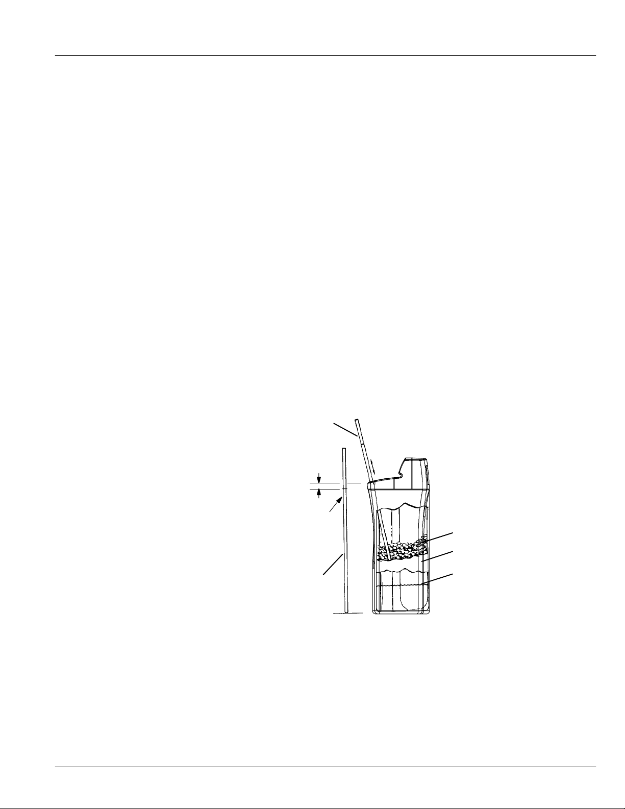
Breaking A Salt Bridge
NOTE: If you see more than a few inches of water in the bottom of the tank, see “Cleaning the
Sometimes, a hard crust or salt bridge forms in the brine tank. It is usually caused by high humidity
or the wrong kind of salt. When the saltbridges, an empty space forms between the water and the salt.
Then, salt will not dissolve in the water to make brine. Without brine, the resin bed does notregenerate
and you will have hard water.
If the storage tank is full of salt, it is hard to tell if you have a salt bridge. Salt is loose on top, but the
bridge is under it. Take a broom handle, or like tool, hold it next to the water softener, measure the
distance from the floor to the rim of the water softener. Then push the broom handle straight down into
the salt. If a hard object is felt, it’s most likely a salt bridge. Carefully push into the bridge in several
places to break it. Do not use any sharp or pointed objects as you may puncture the brine tank.
avoid salt bridging.
Nozzle and Venturi” section.
Push Tool into Salt
Bridge to Break
Figure 12
1” --- 2”
Pencil
Mark
Broom
Handle
Salt
Salt Bridge
Water Level
27
Page 28
Cleaning the Nozzle and Venturi
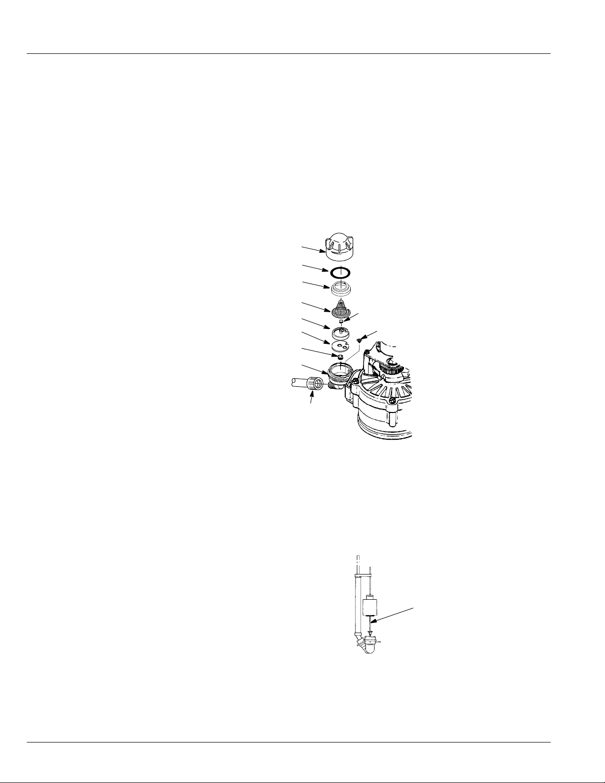
A clean nozzle and venturi (see Figure 13) is a must for the conditioner to work properly. This small
water softener creates the suction to move brine from the brine tank, into the resin tank. If it should
become plugged with sand, silt, dirt, etc., the conditioner will not work, and you will get hard water.
To get to the nozz le and venturi, remove the top cover. Be sure the water softener is in soft water cycle
(no water pressure at nozzle and venturi). Then, holding the nozzle and venturi housing with one hand,
turn off the cap. Do not lose the o--ring seal. Lift out the screen support and screen. Then, remove the
nozzle and venturi. Wash the parts in warm, soapy water and rinse in fresh water. If needed, use a small
brush to remove iron or dirt. Do not scratch, misshape, etc., surfaces of the nozzle and venturi. Also,
check and clean the gasket and flow plug(s).
Replace all parts in the correct order. Lubricate the o--ring seal with silicone grease and locate in
position. Install and tighten the cap, by hand only. Do not overtighten and break the cap or housing.
*Flow plug (HVDC)
Cap
O---ring seal
Screen support
Screen
Nozzle & venturi
Gasket
*Flow plug (1 --- EP)
Screen
Nozzle & venturi housing
IMPORTANT: Be sure
small hole in the gasket is
*Install with lettered side up
concavesidedown.
Ferrule nut
centered directly over the
small hole in the nozzle &
venturi housing.
Figure 13
Recharge the softener several times to reduce water level in the tank. This will also assure that the
softener is completely recharged and ready to provide softened water again. Once the water level in
the tank is about 2” to 3”, you may resume normal use. If the water level does not drop after a couple
of recharges, do the following:
Remove the brine valve assembly from the brinewell and push float stem down. Place opening of brine
valve just under the water and start a recharge. Move the brine valve down with each recharge, until
it rests at the bottom of the tank. Add salt, if needed, and return to normal use.
Brine valve assembly is
inside the brinewell, located
in the salt storage tank.
Float stem
(push down)
28
Figure 14
If you have questions about routine maintenance...
call 1--866--986--3223, Monday -- Friday, 8 am to 9 pm, EST.
Page 29
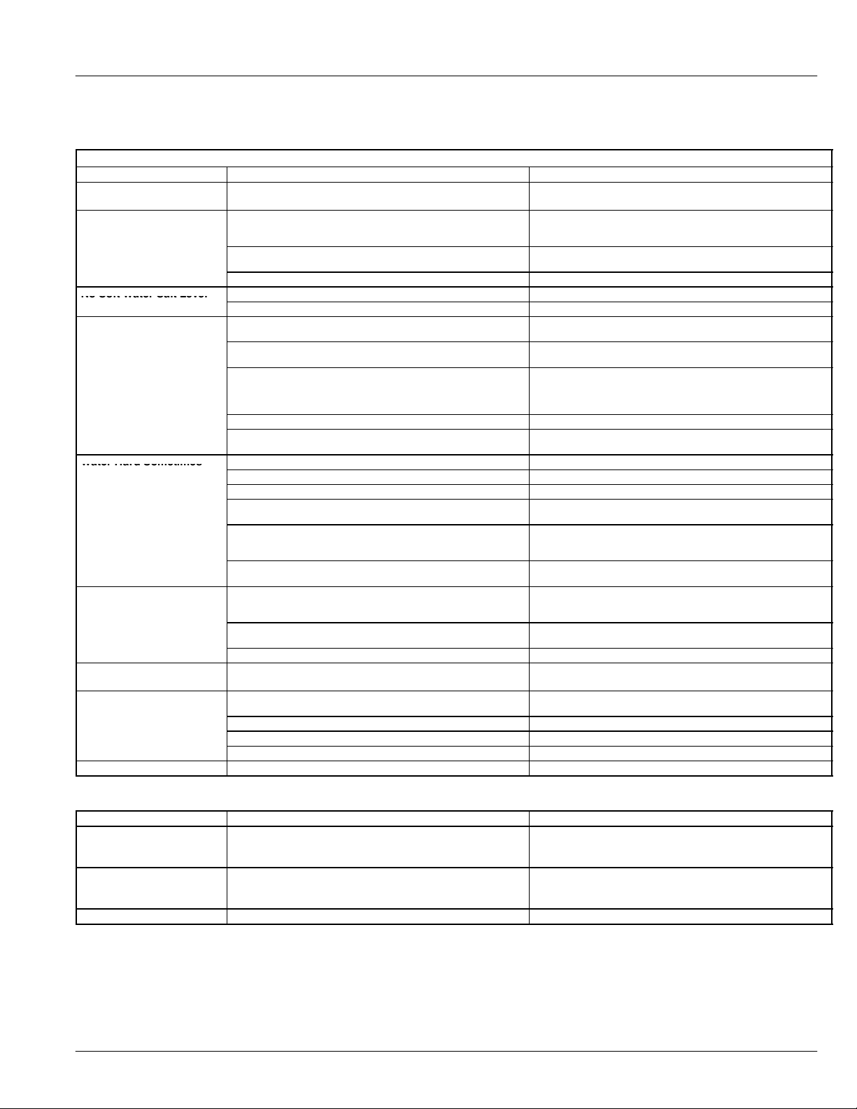
PROBLEM CAUSE SOLUTION
NoSoftWaterSaltLeve
l
g
StorageTankFullOf
WaterHardSometime
s
p
p
appears
No Soft Water
No Soft Water Timer
Display Blank
No Soft Water Salt Level
Not Dropping
No Soft Water, Salt
Stora
eTankFull Of
Water
Water Hard Sometimes
Iron In Water
Motor Stalled Or Clicking
ErrorCodeE1,E3,orE4
a
ears
Error Code E5 appears
Troubleshooting Guide
Need help troubleshooting? Call 1--866--986--3223, Monday -- Friday, 8 am to 9 pm, EST.
Tools Needed For Most Repairs: 5/16 Hex Driver, Phillips Screwdriver, Needle ---nose Pliers
1. No salt in the storage tank. a. Refill with salt.
1. Transformer unplugged at wall outlet, or power cable
disconnected from back of electronic board, transformer
defective.
2. Fuse blown, circuit breaker popped, or circuit switched off.
(See page 24 “Power Outage Memory”).
3. Electronic control board defective. a. Replace Electronic Control Board (PWA). *
1. Salt in storage tank bridged. a. Refer to “Breaking a Salt Bridge” section to break.
2. Manual bypass valve(s) in bypass position. a. Move stem in single valve bypass to service.
1. Dirty, plugged or damaged nozzle & venturi. a. Take apart, clean and inspect nozzle and venturi, see
2. Valve drain hose plugged. a. Hose must not have any kinks, sharp bends or any water flow
3. Low or high system water pressure (low pressure may disrupt
brine draw during recharge, high pressures may cause inner
valve parts failure).
4. Brine valve float dirty or defective. a. Clean or replace Brine Valve Float assembly. *
5. Leak between valve and resin tank assembly. a. Replace o--- rings between resin tank and valve. See water
1. Time setting wrong. a. Check and change time setting.
2. Incorrect water hardness setting. a. Refer to “Set Water Hardness Number” section to set correctly.
3. Incorrect model code programmed. a. Refer to “Program The Water Softener” section to set correctly.
4. Hot water being used when softener is regenerating. a. Avoid using hot water while the softener is regenerating as the
5. Possible increase in water hardness. a. Test the raw water for hardness and iron and program the
6. Leaking faucet or toilet valve. Excessive water usage. a. A small leak will waste hundreds of gallons of water in a few
1. Cl ear water iron in water su pply. a. Test the raw water for hardness and iron and program the
2. Iron in soft water. a. Clean resin bed with Resin Bed Cleaner. Follow instructions on
3. Bacterial or organic bound iron. a. Cannot be treated by water softener.
1. Motor defective or inner valve defect causing high torque on
motor.
1. Wiring Harness or Connection to Position Switch. a. Replace wiring harness or connection to position switch. See
2. Switch. a. Replace switch. See water softener components.
3. Valve Defect Causing High Torque. a. Replace rotor/seal kit.*
4. Motor Inoperative. a. Replace motor. *
1. Electronic Control. a. Replace Electronic Control Board (PWA). *
b. UseRechargefeature.
a. Check for loss of power and correct. Reset electronic controls
andusetheRechargefeature.
a. Replace fuse, reset circuit breaker, or switch circuit on use the
Recharge feature.
“Cleaning the Nozzle and Venturi” section.
blockage, see “Valve Dr ain Requirements” section.
a. If pressure is low, increase well pump output to a minimum 20
psi. Add a pressure reducing valve in the supply pipe to the
softener, if daytime pressure is over 100 psi. Contact a licensed
plumber.
softener components.
water heater will fill with hard water.
water softener accordingly, see “Set Water Hardness Number”
section to set.
days. Fix all leaks and always fully close faucets.
water softener accordingly see “Set Water Hardness Number”
section to set.
package.
a. Replace rotor/seal kit.*
b. Replace motor & switch. See water softener components.
water softener components.
Assistance from customer service may be needed with the following problems and solutions.
PROBLEM CAUSE SOLUTION
Water Running To The
1. Inner valve defect causing leak. a. Replace seals and rotor.
Drain(WhileUnitIsInThe
Soft Water Cycle)
ResinInHousehold
1. Crack in distributor or riser tube. a. Replace distributor or riser tube.
Plumbing, Resin Ta nk
Leaking
Salt Storage Tank Leaking
1. Crack in brine tank. a. Replace salt storage tank.
* Instructions included.
Procedure for removing error code from faceplate:
1. Unplug transformer from outlet.
2. Correct defect.
3. Plug in transformer.
4. Wa it for 6 minutes. The error code will return if the defect was not corrected.
29
Page 30
Automatic Electronic Diagnostics
This water softener has a self--diagnostic function for the electrical system (except input power and/or
water meter). The water softener monitors electronic components and circuits for correct operation.
If a malfunction occurs, an error code appears in the display.
The troubleshooting chart shows the error codes that could appea r, and the possible malfunctions for
each code.
While an error code appears in the display, all buttons are inoperable except the PROGRAM button.
PROGRAM remains operational so the service person can perform the Manual Advance Diagnostics,
see below, to further isolate the problem.
Manual Advance Diagnostics --- Model WHES20
Use the following procedures to advance the water softener through the regeneration cycles to check
operation.
Lift offthe salt hole cover,remove the top cover byunlocking the tabsin the back and rocking forward,
to observe cam and switch operation during valve rotation.
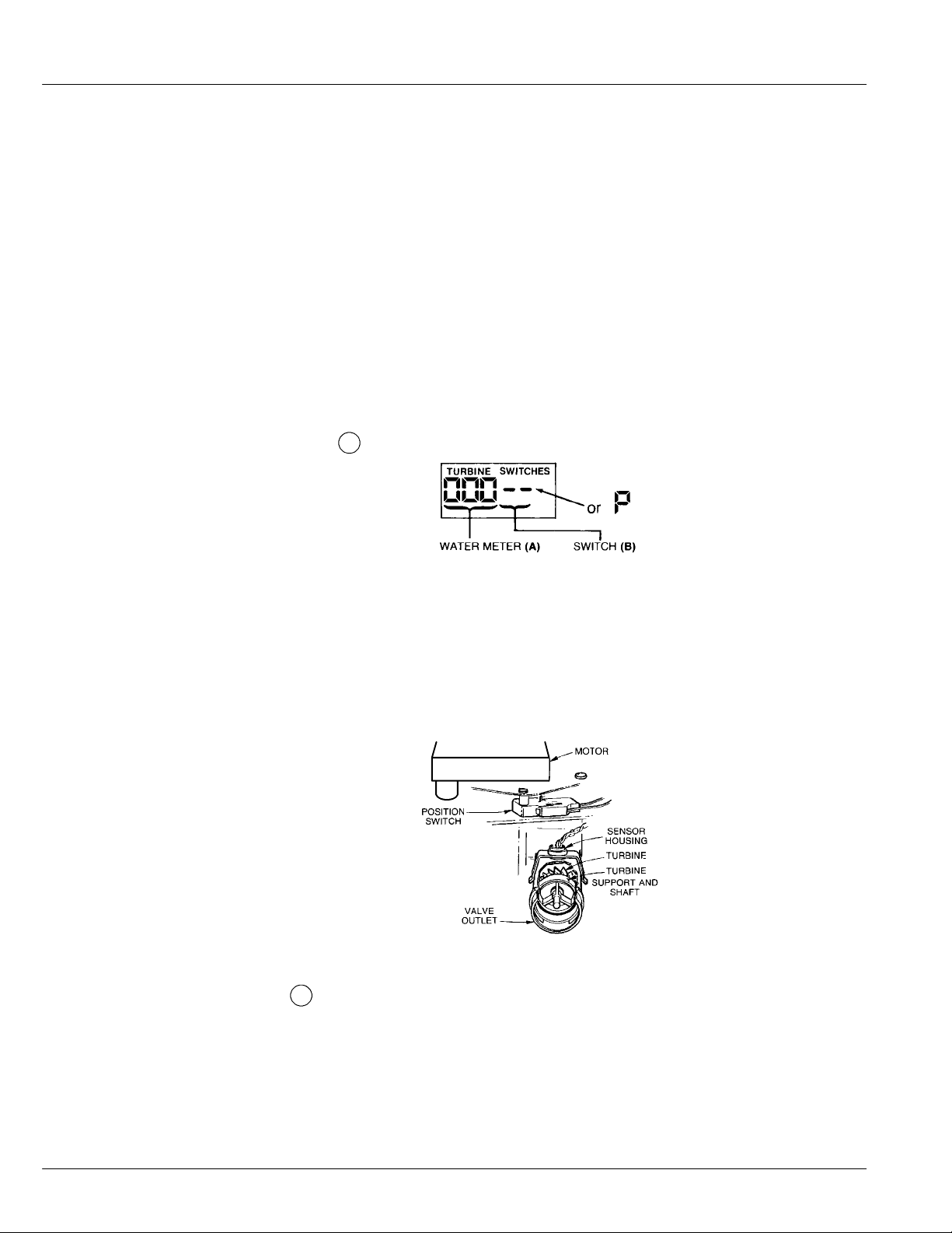
1. Press and hold
2. The first 3 digits indicate water meter operation as follows:
000 (steady) = Soft water not in use, and no flow through the meter.
Open a nearby soft water faucet.
000 to 199 (continual) = Repeats display for each gallon of water passing through the meter.
NOTE: If you don’t get a reading in the display, with faucet open, pull the sensor from the valve
outlet port. Pass a small magnet back and forth in front of the sensor. If you get a reading
in the display with the magnet, unhook the in and out plumbing and check the turbine for
binding.
PROGRAM for 3 seconds until 000 -- -- shows in the display.
30
3. The letter (P) a nd d ash (or dashes) indicate POSITION switch operation. If the letter appears, the
switch is closed. If the dash shows, the switch is open.
4. Use the
switch operation.
NOTE: Be sure water is in contact withthe salt, and not separated by a salt bridge... see “Breaking
5. While in this diagnostic screen, the following inf o rmation is available and may be beneficial for
various reasons. This information is retained by the computer from the first time electrical power
is applied to the face plate.
RECHARGE button to manually advance the valve into each cycle and check correct
A Salt Bridge” section.
Page 31
• Press
+
Up to display the number of days this electronic control has had electrical
power applied.
−
• Press
Down to display the number of regenerations initiated by this electronic
control since the SR code number was entered.
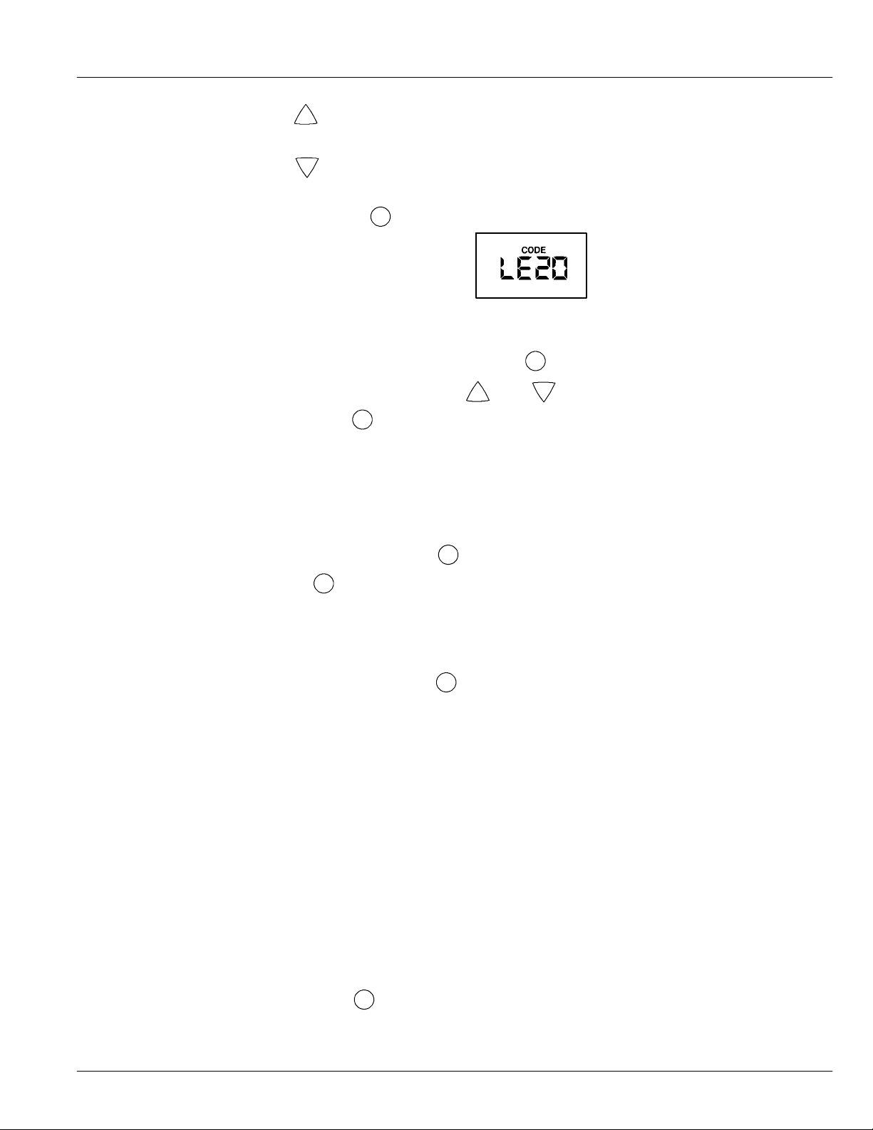
6. Press and hold the
PROGRAM button until LE20 shows in the display.
This code identifies the softener model. If the wrong number shows, the softener will operate on
incorrect programming.
7. Return the present time display — Press the
+
8. To change SR number — Press the
Then, press the
PROGRAM button to return to the present time display .
Up or
PROGRAM button.
−
Down button until the correct SR code shows.
Manual Advance Regeneration Check --- Model WHES20
This check verifies proper operation of the valve motor, brine tank fill, brine draw, regeneration flow
rates, and other controller functions. Always make the initial checks, and the manual initiated
diagnostics.
NOTE: The electronic control display must show a steady time (not flashing). If an error code
shows, first press the
1. Press the
RECHARGE button and hold in for 3 seconds. RECHARGE begins to flash as the
softener enters the fill cycle of regeneration. Remove the brinewell cover and, using a flashlight,
observe fill water entering the tank.
If water does not enter the tank, look for an obstructed nozzle, venturi, fill flow plug, brine tubing, or
brine valve riser pipe.
PROGRAM button to enter the diagnostic display.
2. After observing fill, press the
RECHARGE button to move the softener into brining. A slow
flow of water to the drain will begin. Verify brine draw from the brine tank by shining a flashlight
into the brinewell and observing a noticeable drop in the liquid level. This may take 15 to 20
minutes to notice.
NOTE: Be sure water is in contact withthe salt, and not separated by a salt bridge... see “Breaking
A Salt Bridge” section.
If the water softener does not draw brine, check for (most likely to least likely)
• Dirty or plugged nozzle and venturi, see “Cleaning the Noz zle and Venturi” section
• Nozzle and venturi not seated on the gasket, or gasket deformed
• Restriction invalve drain, causing a back--pressure (bends, kinks, elevated too high,etc.),
see “Install Valve Drain Hose” section
• Obstruction in brine valve or brine tubing
• Inner valve failure (obstructed outlet disc, wave washer deformed, etc.)
NOTE: If water system pressure is low, an elevated drain hose may cause back pressure, stopping
brine draw.
3. Again, press the
RECHARGE buttonto move the softener into backwash. Look for a fast flow
of water from the drain hose.
An obstructed flow indicates a plugged top distributor, backwash flow plug, or drain hose.
31
Page 32
4. Press the RECHARGE button to move the softener into fast rinse. Again look for a fast drain
flow. Allow the softener to rinse for a few minutes to flush out any brine that may remain in the
resin tank from the brining cycle test.
5. To return the softener to service, press the RECHARGE button.
Manual Advance Diagnostics --- Model WHES30
Use the following procedures to advance the water softener through the regeneration cycles to check
operation.
Lift offthe salt hole cover,remove the top cover byunlocking the tabsin the back and rocking forward,
to observe cam and switch operation during valve rotation.
1. Press and hold
PROGRAM for 3 seconds until 000 -- -- shows in the display.
2. The first 3 digits indicate water meter operation as follows:
000 (steady) = Soft water not in use, and no flow through the meter.
Open a nearby soft water faucet.
000 to 199 (continual) = Repeats display for each gallon of water passing through the meter.
NOTE: If you don’t get a reading in the display, with faucet open, pull the sensor from the valve
outlet port. Pass a small magnet back and forth in front of the sensor. You should get a
reading in the display. If you get a reading, unhook the in and out plumbing and check the
turbine for binding.
32
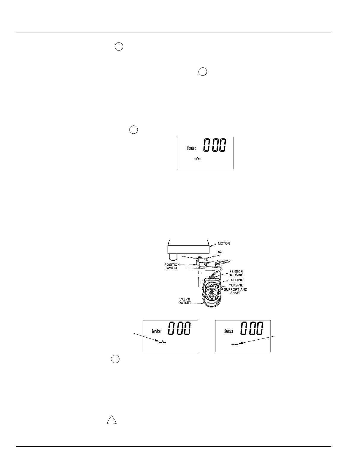
3. Symbols in the display indicate POSITION switch operation.
Switch is open
(cam not rotating)
Switch is closed
(Cam rotating)
4. Use the RECHARGE button to manually advance the valve intoeach cycle and check correct
switch operation.
NOTE: Be sure water is in contact withthe salt, and not separated by a salt bridge... see “Breaking
A Salt Bridge” section.
5. While in this diagnostic screen, the following inf o rmation is available and may be beneficial for
various reasons. This information is retained by the computer from the first time electrical power
is applied to the face plate.
+
• Press
Up to display the number of days this electronic control has had electrical
power applied.
Page 33
−
• Press
Down to display the number of regenerations initiated by this electronic
control since the LE code number was entered.
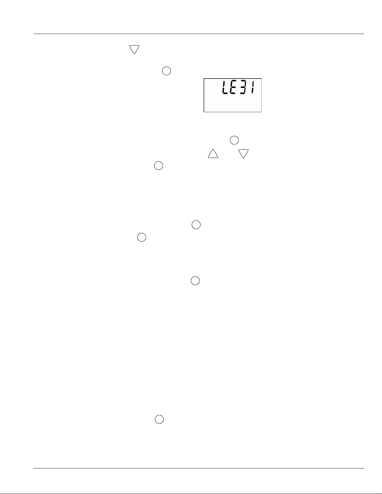
6. Press and hold the
PROGRAM button until LE31 shows in the display.
This code identifies the softener model. If the wrong number shows, the softener will operate on
incorrect programming.
7. Return the present time display — Press the
+
8. To change LE number — Press the
Then, press the
PROGRAM button to return to the present time display .
Up or
PROGRAM button.
−
Down button until the correct code shows.
Manual Advance Regeneration Check --- Model WHES30
This check verifies proper operation of the valve motor, brine tank fill, brine draw, regeneration flow
rates, and other controller functions. Always make the initial checks, and the manual initiated
diagnostics.
NOTE: The electronic control display must show a steady time (not flashing). If an error code
shows, first press the
1. Press the
RECHARGE button and hold in for 3 seconds. RECHARGE begins to flash as the
softener enters the fill cycle of regeneration. Remove the brinewell cover and, using a flashlight,
observe fill water entering the tank.
If water does not enter the tank, look for an obstructed nozzle, venturi, fill flow plug, brine tubing, or
brine valve riser pipe.
2. After observing fill, press the
flow of water to the drain will begin. Verify brine draw from the brine tank by shining a flashlight
into the brinewell and observing a noticeable drop in the liquid level. This may take 15 to 20
minutes to notice.
NOTE: Be sure water is in contact withthe salt, and not separated by a salt bridge... see “Breaking
A Salt Bridge” section.
PROGRAM button to enter the diagnostic display.
RECHARGE button to move the softener into brining. A slow
If the water softener does not draw brine, check for (most likely to least likely)
• Dirty or plugged nozzle and venturi, see “Cleaning the Noz zle and Venturi” section
• Nozzle and venturi not seated on the gasket, or gasket deformed
• Restriction invalve drain, causing a back--pressure (bends, kinks, elevated too high,etc.),
see “Install Valve Drain Hose” section
• Obstruction in brine valve or brine tubing
• Inner valve failure (obstructed outlet disc, wave washer deformed, etc.)
NOTE: If water system pressure is low, an elevated drain hose may cause back pressure, stopping
brine draw.
3. Again, press the
RECHARGE buttonto move the softener into backwash. Look for a fast flow
of water from the drain hose.
An obstructed flow indicates a plugged top distributor, backwash flow plug, or drain hose.
33
Page 34
4. Press the RECHARGE button to move the softener into fast rinse. Again look for a fast drain
flow. Allow the softener to rinse for a few minutes to flush out any brine that may remain in the
resin tank from the brining cycle test.
5. To return the softener to service, press the RECHARGE button.
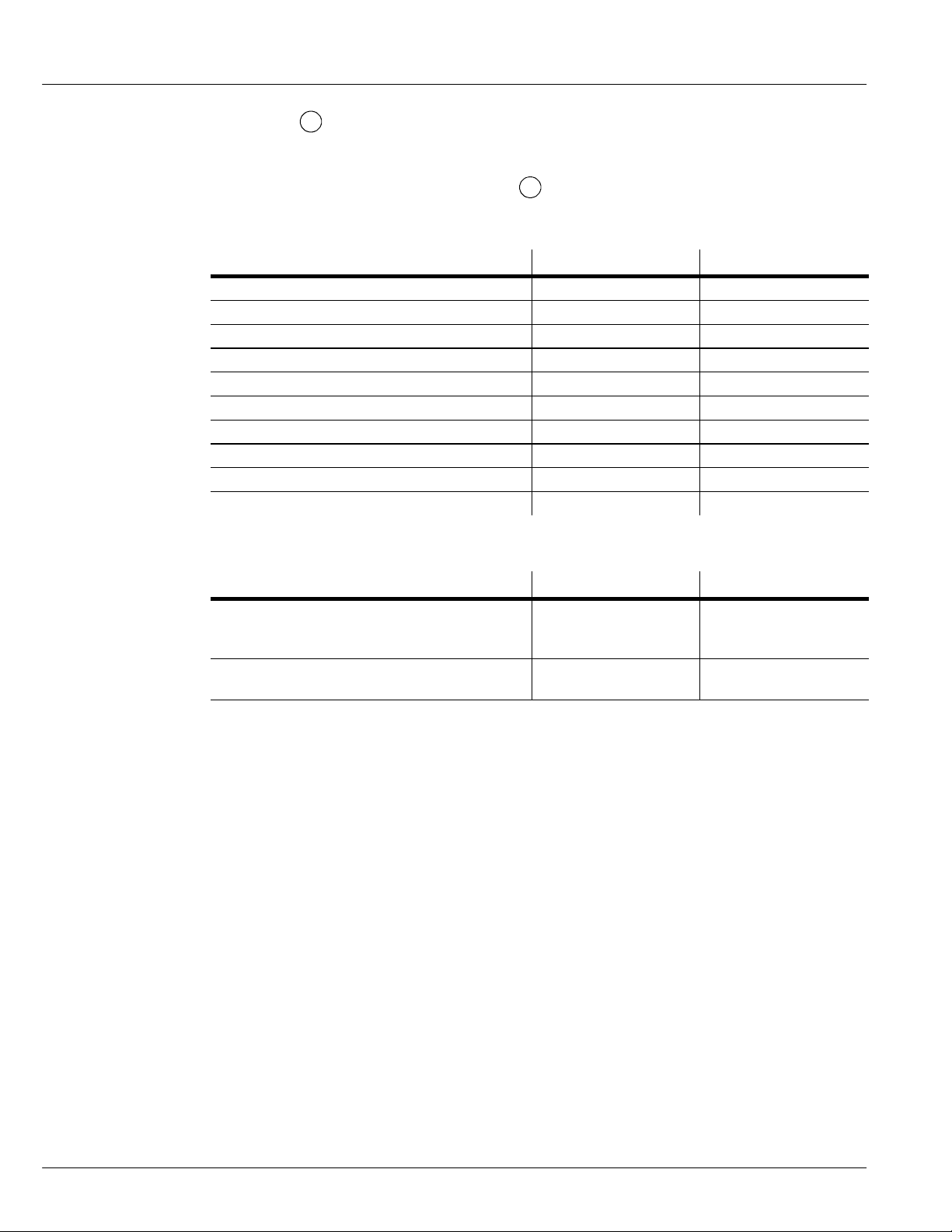
Product Specifications
Rated Service Flow Rate (gpm) 6.0 8.0
Amount of High Capacity Resin (cu ft) .57 .82
Pressure Drop at Rated Service Flow (psig) 10 12
Water Supply Max. Hardness (gpg) 50 95
Water Supply Max. Clear Water Iron (ppm) 3 5
Water Pressure Limits (min./max. psi) 20 --- 125 20 --- 125
Min. --- Max. Water Temperature (˚F) 40 --- 120 40 --- 120
Min. Water Supply Flow Rate (gpm) 3 3
Max. Drain Flow Rate (gpm) 2.0 2.0
Salt storage capacity 175 lbs. 175 lbs.
Performance Claims
WHES20 WHES30
Rated Softening Capacity
(Grains @ Salt Dose)
Rated Efficiency (Grains/Pound of Salt @
Minimum Salt Dose)
These systems conform to NSF/ANSI 44 for the specific performance claims as verified and
substantiated by test data.
The efficiency rating is only valid at the stated salt dose. These softeners were efficiency rated
according to NSF/ANSI Standard 44.
Variable Sa lt Dose
The salt dose is selected by the electronic controls at regeneration time based on the amount needed.
WHES20 WHES30
8,700 @ 1.7 lbs.
16,800 @ 5.4 lbs.
20,100 @ 9.1 lbs.
5000 @1.7 lbs. 5,000 @2.9 lbs.
14,700 @ 2.9 lbs.
25,400 @ 8.0 lbs.
30,100 @ 13.1 lbs.
34
Page 35
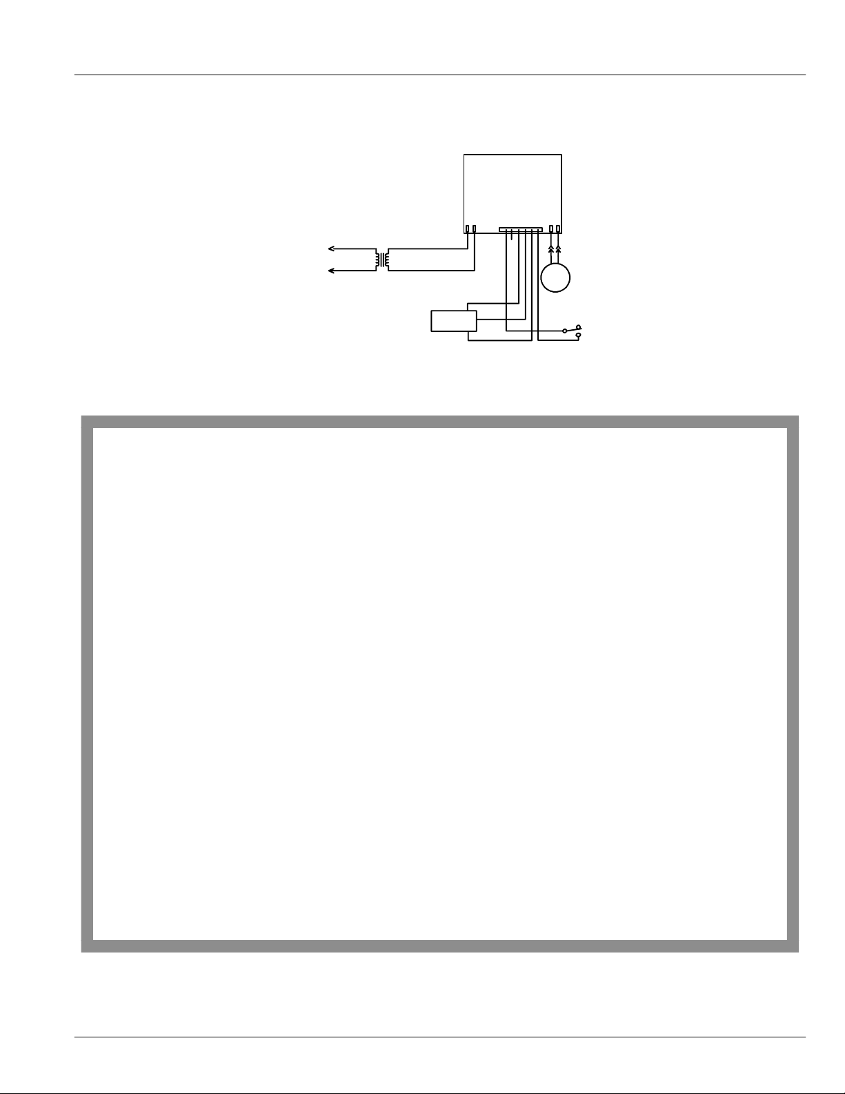
Wiring Schematic
Direct plug--in
transformer
120 vac
24 vac
Back of electronic board
M
24V
Turb ine
sensor
NO
NC
Position switch
Warranty
WATER SOFTENER WARRANTY
Warrantor: Ecodyne Water Systems LLC, 1890 Woodlane Drive, Woodbury, MN 55125
Warrantor guarantees, to the original owner, that:
One Year Full Warranty:
For a period of one (1) year after installation, all parts will be free of defects in materials and workmanship and will perform their
normal functions.
For a period of one (1) year after installation, labor to repair or replace any part deemed to be defective in materials or workmanship, will be provided at no additional cost.
Limited Warranties:
Limited ten (10) year warranty, from date of purchased, the salt storage tank and fiberglass mineral tank will not rust, corrode,
leak, burst, or in any other manner, fail to perform their proper functions; and that
Limited three (3) year warranty, after installation, the electronic control board will be free of defects in materials and workmanship
and will perform its normal functions.
If, during such respective period, a part proves to be defective, Warrantor will ship a replacement part, directly to yourhome, withoutcharge.
After the first year, labor necessary to maintain this product is not covered by the product warranty.
If you have questions regarding a warranted product, need assistance with installation or trouble shooting, wish to order a part or report a
warranty issue, we are just a phone call away. Simply dial 1--866--986--3223, Monday -- Friday, 8 am -- 9 pm EST, for assistance.
General Provisions
The above warranties are effective provided the water conditioner is operated at water pressures not exceeding 125 psi, and at water
temperatures not exceeding 120°F; provided further that the water conditioner is not subject to abuse, misuse, alteration, neglect, freezing,
accident or negligence; and provided further that the water conditioner is not damaged as the result of any unusual force of nature such as,
but not limited to, flood, hurricane, tornado or earthquake.
Warrantor is excused if failureto performits warrantyobligationsistheresult of strikes,governmentregulation,materialsshortages, or other
circumstances beyond its control.
*THERE ARE NO WARRANTIES ON THE WATER CONDITIONER BEYOND THOSE SPECIFICALLY DESCRIBED ABOVE.
ALL IMPLIED WARRANTIES, INCLUDING ANY IMPLIED WARRANTY OF MERCHANTABILITY OR OF FITNESS FOR A
PARTICULAR PURPOSE, ARE DISCLAIMED TO THE EXTENT THEY MIGHT EXTEND BEYOND THE ABOVE PERIODS.
THE SOLE OBLIGATION OF WARRANTOR UNDER THESE WARRANTIES IS TO REPLACE OR REPAIR THE COMPONENT
OR PART WHICH PROVESTO BE DEFECTIVE WITHIN THE SPECIFIED TIME PERIOD, AND WARRANTOR IS NOT LIABLE
FOR CONSEQUENTIAL OR INCIDENTAL DAMAGES.NO WARRANTORDEALER, AGENT, REPRESENTATIVE,OR OTHER
PERSON IS AUTHORIZED TO EXTEND OR EXPAND THE WARRANTIES EXPRESSLY DESCRIBED ABOVE.
Some states do not allow limitations on how long an implied warranty lasts or exclusions or limitations of incidental or consequential
damage, so the limitations and exclusions in this warrantymay not applyto you. Thiswarranty gives you specificlegalrights, and you may
have other rights which vary from state to state. This warranty applies to consumer-- owned installations only.
R
Registered trademark/TM Trademark of Whirlpool, USA, used under license.
E
2004 Whirlpool Corporation. All rights reserved.
TEFLON is a registered trademark of E. I. DuPont.
35
Page 36
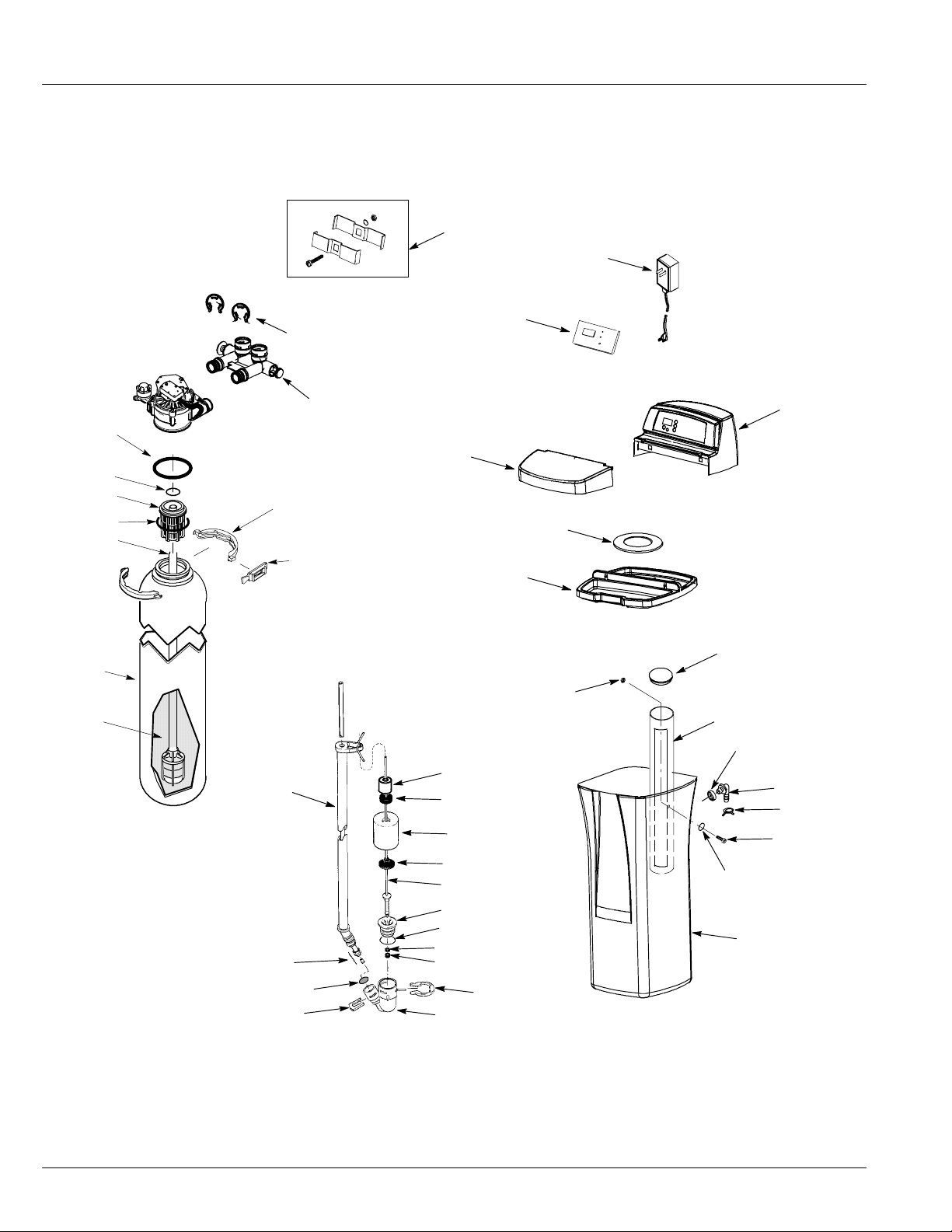
Softener Components
40
42
25
26
41
1
28
2
3
4
5
8
9
10
11
6
29
7
24
23
22
21
20
19
18
17
16
30
32
31
33
8
7
6
5
38
27
34
35
36
37
39
36
13
12
15
14
Page 37
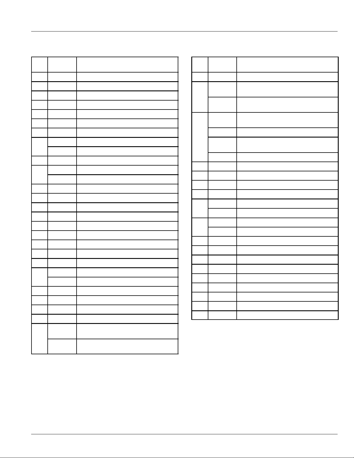
Softener Components
Key
Part No. Description
No.
1 7170296 O--Ring, 2--7/8” x 3--1/4”
2 7170254 O--Ring, 13/16” x 1--1/16”
3 7077870 Top Distributor
4 7170270 O--Ring, 2--3/4” x 3”
5 7105047 Rep’l Bottom Distributor
6 7176292 ClampSection(2req.)
7 7088033 Retainer Clip (2 req.)
8 7114787 Rep’l Resin Tank, Model WHES20
7264922 Rep’l Resin Tank, Model WHES30
9 0502272 Resin, 1 cu. ft.
10 7095470 Brine Tube, Model WHES20
7221746 Brine Tube, Model WHES30
11 7113016 Tubing Assembly
12 7131365 Screen
13 7080653 Clip
14 7092252 Brine Valve Body
15 1205500 Clip
16 0516924 Bottom Seal Retainer
17 0516211 Seal
18 7170288 O--Ring, 15/16 x 1--3/16
19 7092278 Guide Cap
20 7093216 Float Rod & Stem, Model WHES20
7220627 Float Rod & Stem, Model WHES30
21 0516947 Float Seal
22 7097202 Float (includes Key No. 21)
23 0513860 Float Stop
24 7168647 Ceramic Weight
-- 7145259 Rep’l Brine Valve Asm.,
Model WHES20
7239155 Rep’l Brine Valve Asm.,
Model WHES30
Key
Part No. Description
No.
25 7275907 Transformer
26 7285847 Rep’l Electronic Control Board (PWA),
Model WHES20
7285863 Rep’l Electronic Control Board (PWA),
Model WHES30
27 7267108 Top Cover & Faceplate Asm,
Model WHES20 (order decal, below)
7262831 Faceplate Decal, Model WHES20
7267116 Top Cover & Faceplate Asm,
Model WHES30 (order decal, below)
7262849 Faceplate Decal, Model WHES30
28 7262661 Salt Hole Cover
29 7141001 Vapor Barrier
30 7262653 Rim
31 7082150 Nut
32 7155115 Brinewell Cover. Model WHES20
7219888 Brinewell Cover. Model WHES30
33 7109871 Brinewell, Model WHES20
7214375 Brinewell, Model WHES30
34 9003500 Grommet
35 1103200 Hose Adaptor
36 0900431 Hose Clamp
37 7262792 Screw
38 7003847 O--Ring
39 7264875 Rep’l Brine Tank
40 7248706 Grounding Kit
41 7278434 Bypass Valve
42 7116713 Clips (2 req.)
37
Page 38
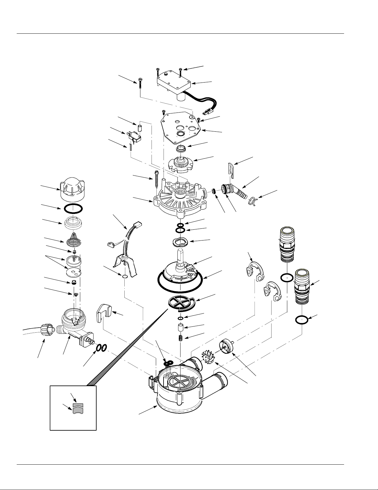
Softener Components
47
1
2
39
38
37
36
34
33
32
35
40
45
44
41
46
42
43
12
13
3
4
5
6
11
14
15
16
17
7
8
9
10
21
22
38
31
30
29
wear--strip
seal
cross--section
view
28
26
27
18
19
20
23
24
25
Page 39
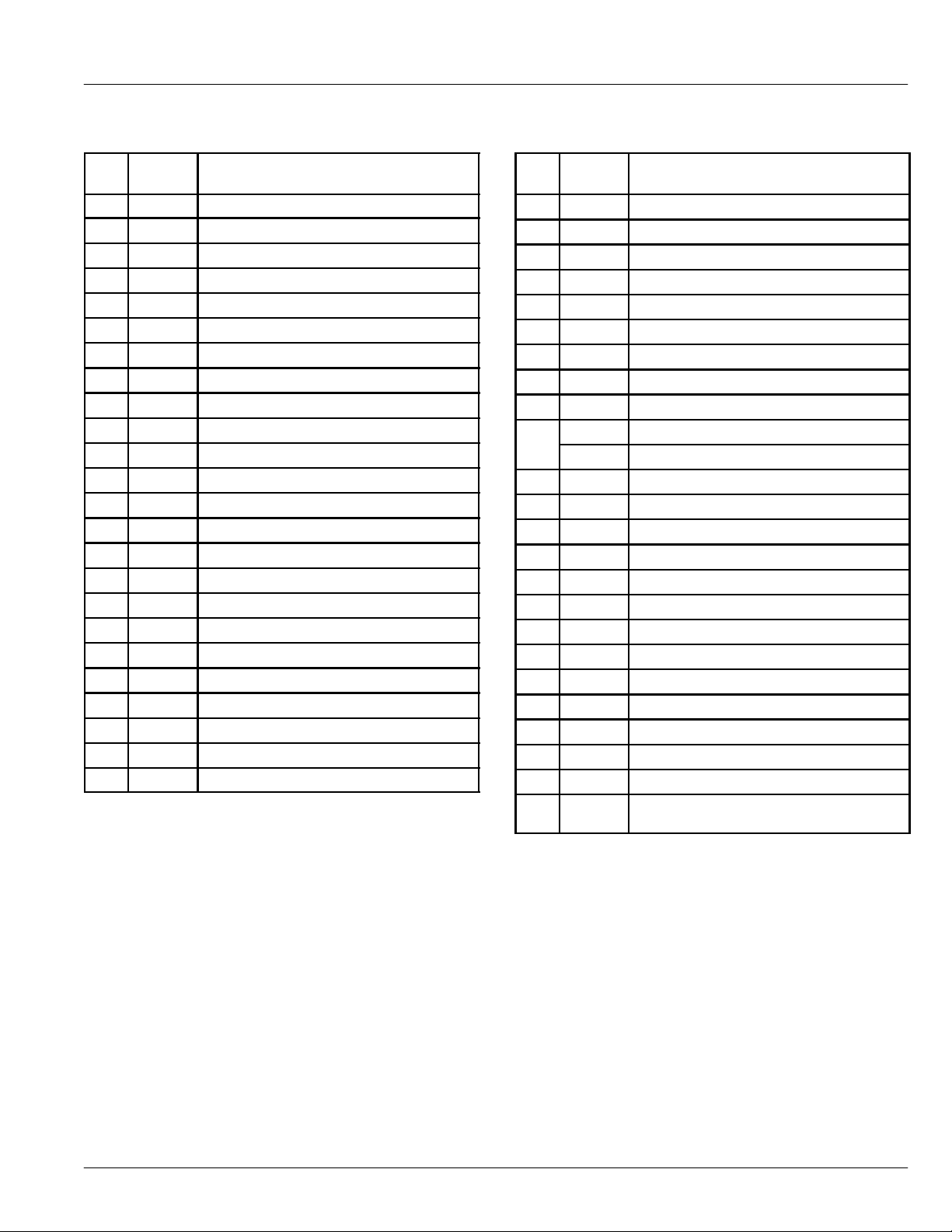
Softener Components
Key
No.
10 7170327 O-Ring, 5/8 x 13/16
11 0501228 Flow Plug
12 7170238 O-Ring, 7/16 x 5/8
13 7170212 O-Ring, 3/4 x 15/16
14 7082087 Wave Washer
15 7199232 Rotor & Disc
16 7170246 O-Ring, 3--3/8 x 3-5/8
17 7134224 Rotor Seal
18 7170204 O-Ring, 3/8 x 9/16
19 7092642 Plug (Drain Seal)
20 7129889 Spring
21 7116713 Clip (2 req.)
22 7278442 Installation Adaptor (2 req.)
23 7170288 O--Ring(2req.)
24 2204101 Turbine Support and Shaft
Part
No.
1 7224087 Screw,#8-32x1”(2req.)
2 7286039 Motor (incl. 2 ea. of Key No. 1)
3 0900857 Screw, #6-20 x 3/8 (2 req.)
4 7231385 Motor Plate
5 0503288 Bearing
6 7284964 Cam and Gear
7 7142942 Clip (Drain)
8 7024160 Drain Hose Adaptor
9 0900431 Tubing Clamp
Description
Key
No.
25 7117858 Turbine
26 7082053 Valve Body
27 7081764 Seal (Nozzle & Venturi)
28 7081201 Retainer (Nozzle & Venturi)
29 7170319 O-Ring, 1/4 x 3/8 (2 req.)
30 7081104 Nozzle & Venturi Housing
31 1202600 Nut - Ferrule
32 7095030 Cone Screen
33 1148800 Flow Plug, .3 gpm
34 7187772 Nozzle & Venturi Gasket Kit
35 0521829 Flow Plug, .1 gpm
36 7146043 Screen
37 7167659 Screen Support
38 7170262 O-Ring, 1--1/8” x 1-- 3/8”
39 7199729 Cap1
40 0900060 O-Ring
41 7276076 Sensor Housing & Wiring Harness
42 7085263 Valve Cover
43 7074123 Screw, #10-14x2(5req.)
44 7077472 Expansion Pin
45 7030713 Switch
46 7117816 Spacer
47 7070412 Screw, #4-24 x 1-1/8 (flat head)
z 7187065 Nozzle & Venturi Asm. (incl. Key Nos.
Part
No.
7204362 Gasket (only)
30, & 32 -- 39)
Description
z Not shown.
Manufactured and warranted by
Ecodyne Water Systems LLC
1890 Woodlane Drive
Woodbury, MN 551
25
39
 Loading...