

Whirlpool WHAPSRO Installation And Operation Manual
Model WHAPSRO
®
How to install, operate
and maintain your
Reverse Osmosis
Drinking Water System
Do not return unit to store
If you have any questions or concerns when
installing, operating or maintaining your reverse
osmosis system, call our toll free number:
1-866-986-3223
or visit whirlpoolwatersolutions.com
When you call, please be prepared to provide
the model, date code and serial number of your
product, found on the rating decal, located
inside the cover.
System tested and certified by NSF International
against NSF/ANSI Standards 42 & 58. See
performance data on pages 25 & 26 for details.
Manufactured and warranted by
Ecodyne Water Systems
1890 Woodlane Drive
Woodbury, MN 55125
Installation and Operation Manual
201-8404240 (Rev. 04 7/21/17)

TABLE OF CONTENTS
Page
Specifications & Dimensions . . . . . . . . . . . . . . . . . . . . . . . . . . . . . . . . . . . . . . . . . . . . . . . . . . . . . . . . . . . . . . . . . . . 3
Inspect Shipment . . . . . . . . . . . . . . . . . . . . . . . . . . . . . . . . . . . . . . . . . . . . . . . . . . . . . . . . . . . . . . . . . . . . . . . . . . . . 4
Plan Your Installation . . . . . . . . . . . . . . . . . . . . . . . . . . . . . . . . . . . . . . . . . . . . . . . . . . . . . . . . . . . . . . . . . . . . . . . 5-6
Overview & Site Preparation . . . . . . . . . . . . . . . . . . . . . . . . . . . . . . . . . . . . . . . . . . . . . . . . . . . . . . . . . . . . . . . . . . . 6
nstallation Instructions . . . . . . . . . . . . . . . . . . . . . . . . . . . . . . . . . . . . . . . . . . . . . . . . . . . . . . . . . . . . . . . . . . . . . 7-16
I
Step A - Install Supply Water Fitting . . . . . . . . . . . . . . . . . . . . . . . . . . . . . . . . . . . . . . . . . . . . . . . . . . . . . . . . . . 7
Step B - Install Reverse Osmosis Drain . . . . . . . . . . . . . . . . . . . . . . . . . . . . . . . . . . . . . . . . . . . . . . . . . . . . . 8-9
Step C - Install Reverse Osmosis Filter Assembly . . . . . . . . . . . . . . . . . . . . . . . . . . . . . . . . . . . . . . . . . . . . . . 10
Step D - Install Storage Tank . . . . . . . . . . . . . . . . . . . . . . . . . . . . . . . . . . . . . . . . . . . . . . . . . . . . . . . . . . . . . . 10
Step E - Install Reverse Osmosis Faucet . . . . . . . . . . . . . . . . . . . . . . . . . . . . . . . . . . . . . . . . . . . . . . . . . . 11-12
Step F - Connect Tubes . . . . . . . . . . . . . . . . . . . . . . . . . . . . . . . . . . . . . . . . . . . . . . . . . . . . . . . . . . . . . . . 13-14
Step G - Sanitize, Pressure Test & Purge System . . . . . . . . . . . . . . . . . . . . . . . . . . . . . . . . . . . . . . . . . . . 15-16
How Your Reverse Osmosis System Works . . . . . . . . . . . . . . . . . . . . . . . . . . . . . . . . . . . . . . . . . . . . . . . . . . . 17-18
Maintenance . . . . . . . . . . . . . . . . . . . . . . . . . . . . . . . . . . . . . . . . . . . . . . . . . . . . . . . . . . . . . . . . . . . . . . . . . . . . 19-20
Troubleshooting . . . . . . . . . . . . . . . . . . . . . . . . . . . . . . . . . . . . . . . . . . . . . . . . . . . . . . . . . . . . . . . . . . . . . . . . . . . . 21
Exploded View & Parts List . . . . . . . . . . . . . . . . . . . . . . . . . . . . . . . . . . . . . . . . . . . . . . . . . . . . . . . . . . . . . . . . 22-23
Warranty . . . . . . . . . . . . . . . . . . . . . . . . . . . . . . . . . . . . . . . . . . . . . . . . . . . . . . . . . . . . . . . . . . . . . . . . . . . . . . . . . 24
Performance Data . . . . . . . . . . . . . . . . . . . . . . . . . . . . . . . . . . . . . . . . . . . . . . . . . . . . . . . . . . . . . . . . . . . . . . . 25-27
2
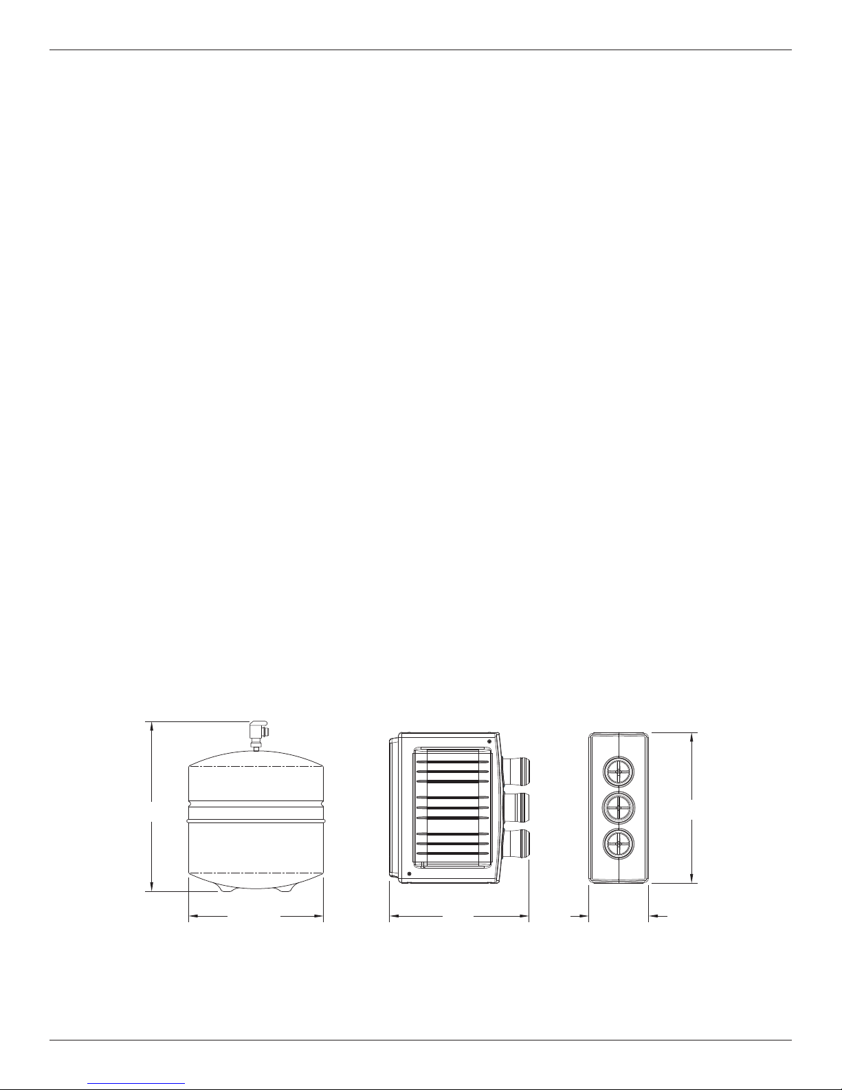
Specifications & Dimensions
5-1/2"
14"
11" dia.
17"
13”
Supply water pressure limits . . . . . . . . . . . . . . . . . . . . . . . . . . . . . . . . . . . . . . . . . . . . . . 40-100 psi (280-689 kPa)
Supply water temperature limits . . . . . . . . . . . . . . . . . . . . . . . . . . . . . . . . . . . . . . . . . . . . . 40-100 °F (4.5-37.7°C)
aximum total dissolved solids (TDS) . . . . . . . . . . . . . . . . . . . . . . . . . . . . . . . . . . . . . . . . . . . . . . . . . . 2000 ppm
M
Maximum water hardness @ 6.9 pH . . . . . . . . . . . . . . . . . . . . . . . . . . . . . . . . . . . . . . . . . . . . . . . . . . . . . . . 10 gpg
Maximum iron, manganese, hydrogen sulfide . . . . . . . . . . . . . . . . . . . . . . . . . . . . . . . . . . . . . . . . . . . . . . . . . . . . 0
Chlorine in water supply (max. ppm) . . . . . . . . . . . . . . . . . . . . . . . . . . . . . . . . . . . . . . . . . . . . . . . . . . . . . . . . . 2.0
Supply water pH limits (pH) . . . . . . . . . . . . . . . . . . . . . . . . . . . . . . . . . . . . . . . . . . . . . . . . . . . . . . . . . . . . . . . . 4-10
Product (quality) water, 24 hours
Percent rejection of TDS, minimum (new membrane)1 . . . . . . . . . . . . . . . . . . . . . . . . . . . . . . . . . . . . . . . . . . . 86.5
Automatic shutoff control . . . . . . . . . . . . . . . . . . . . . . . . . . . . . . . . . . . . . . . . . . . . . . . . . . . . . . . . . . . . . . . . . . yes
Efficiency
2
. . . . . . . . . . . . . . . . . . . . . . . . . . . . . . . . . . . . . . . . . . . . . . . . . . . . . . . . . . . . . . . . . . . . . . . . . . . 12.2 %
Recovery3 . . . . . . . . . . . . . . . . . . . . . . . . . . . . . . . . . . . . . . . . . . . . . . . . . . . . . . . . . . . . . . . . . . . . . . . . . . . 22.9 %
This system conforms to NSF/ANSI 58 for the specific performance claims as verified and substantiated by test data.
1
@ Feed water supply at 50 psi, 77°F, and 750 TDS --- Quality water production, amount of waste water and percent rejection
all vary with changes in pressure, temperature and total dissolved solids.
2
Efficiency rating means the percentage of the influent water to the system that is available to the user as reverse osmosis treated water under operating conditions that approximate typical daily usage.
3
Recovery rating means the percentage of the influent water to the membrane portion of the system that is available to the user
as reverse osmosis treated water when the system is operated without a storage tank or when the storage tank is bypassed.
Non-potable Water Sources: Do not attempt to use this product to make safe drinking water from non-potable water sources. Do not
use the system on microbiologically unsafe water, or water of unknown quality without an adequate disinfection before or after the
system. This system is certified for cyst reduction and may be used on disinfected water that may contain filterable cysts.
Arsenic Reduction: This system shall only be used for arsenic reduction on chlorinated water supplies containing detectable residual
free chlorine at the system inlet. Water systems using an inline chlorinator should provide a one minute chlorine contact time before
the reverse osmosis system.
Nitrate/Nitrite Test Kit: This system is supplied with a nitrate/nitrite test kit. Product water should be monitored periodically according
to the instructions provided with the test kit.
Installations in the Commonwealth of Massachusetts: The Commonwealth of Massachusetts requires installation be performed by
a licensed plumber and do not permit the use of saddle valves. Plumbing code 248-CMR of the Commonwealth of Massachusetts
must be followed in these cases.
State of California Proposition 65 Warning: This product contains one or more chemicals known to the State of California to cause
cancer, birth defects, or other reproductive harm.
Product Water Testing: The Reverse Osmosis system contains a replaceable treatment component critical for the effective reduction
of total dissolved solids. Product water should be tested periodically to verify that the system is performing properly.
Replacement of the reverse osmosis component: This reverse osmosis system contains a replaceable component critical to the
efficiency of the system. Replacement of the reverse osmosis component should be with one of identical specifications, as defined by
the manufacturer, to assure the same efficiency and contaminant performance.
1
. . . . . . . . . . . . . . . . . . . . . . . . . . . . . . . . . . . . . . . . . . . . . . 18.4 gal. (69.6 liters)
17”
Questions? Call Toll Free 1-866-986-3223 or visit whirlpoolwatersolutions.com
When you call, please be prepared to provide the model, date code and serial number,
found on the rating decal, located inside the cover.
14”
13”11” dia.
5-1/2”
FIG. 1
3
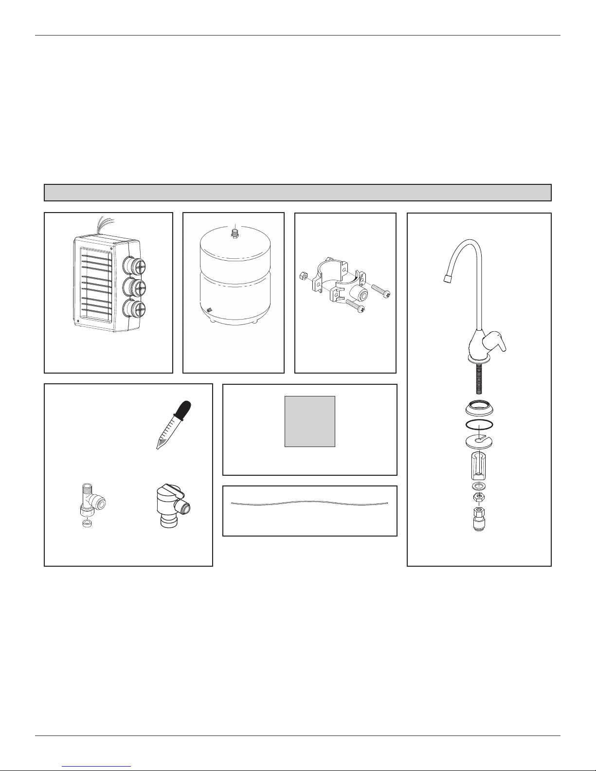
Inspect Shipment
Your Reverse Osmosis Drinking Water System is
shipped complete in one carton. Remove all items
rom your shipping carton.
f
heck all items against the packing list below. Note
C
any items lost or damaged in shipment.
Reverse Osmosis Assembly
With Red, Yellow, Blue &
Green tubes attached
Water Storage Tank
Note any damage to the shipping carton. Refer to the
exploded view and parts list in the back of the manual
or the part names and numbers of missing or dam-
f
aged items. If problems exist, refer to the website or
the toll free number listed throughout this manual.
eep the small parts in the parts bag until you are
K
ready to install them.
Packing List
Drain Adapter
Bag
Bag
Parts Bag
Water Supply
Fitting
Dropper
Tank
Connector
Nitrate/Nitrite Test Kit
Black Drain Tube
Reverse Osmosis
Faucet Assembly
FIG. 2
4
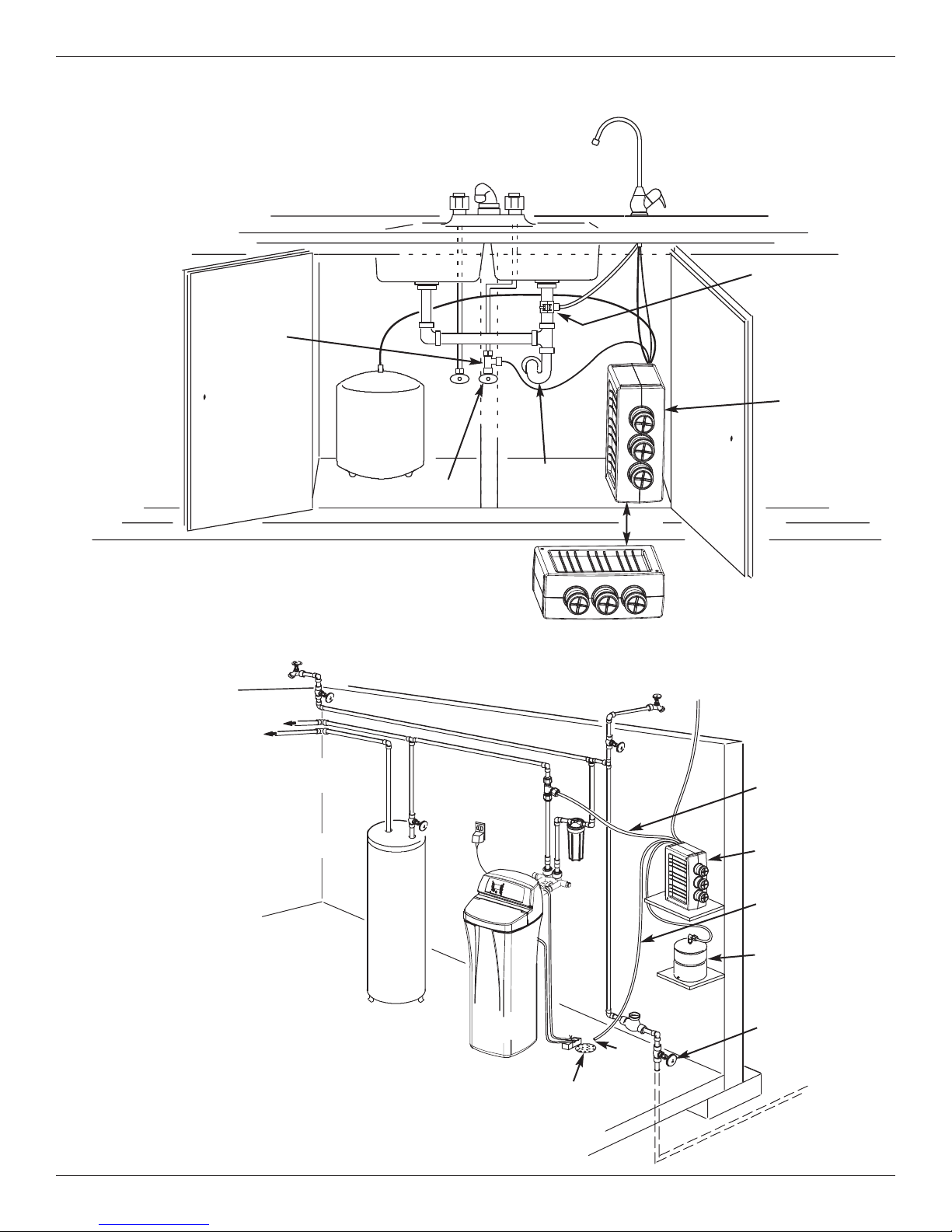
Plan Your Installation
All install parts included in package.
Cold Water
Supply
Drain Adapter
for Reverse
Osmosis
aste Water
W
HOT COLD
Storage
Tank
Shutoff Valve
Typical Under Sink Installation
Outside Faucet
(Hard Water)
Soft, Cold Water
Soft, Hot
Water
H
a
rd
Wa
te
r L
Sink Drain
P-Trap
in
e
Shutoff
Valve
Reverse
Osmosis
Assembly
ORe
FIG. 3
Outside Faucet
(Hard Water)
To Faucet
Soft water to
Reverse Osmosis
System
IMPORTANT: Allow adequate open
space behind the
water filtration system
to avoid sharp bends
or kinks in the tubing.
Typical Remote Installation
Additional parts required.
Water
Heater
Water
Softener
5
Hard
Water to
House
Floor
Drain
Air
Gap
(see
p. 9)
Water
Meter
Reverse Osmosis
System
Reverse Osmosis
Drain
Storage
Tank
Main
Shutoff
Valve
FIG. 4
Plan Your Installation
ead through the entire manual before beginning
R
your installation. Follow all steps exactly. Reading
this manual will also help you get all the benefits from
your system.
Your Reverse Osmosis Drinking Water System can be
installed under a sink or in a remote location. Typical
remote sites are a laundry room or utility room. Review
the location options below and determine where you
are going to install your system.
NOTE: For best system performance, the feed water
to the system should be softened or have hardness less than 10 grains per gallon, with no iron,
manganese or hydrogen sulfide.
UNDER THE SINK LOCATION
The Reverse Osmosis Filter Assembly and storage
tank may be installed in a kitchen or bathroom sink
cabinet. See Fig. 3.
TOOLS NEEDED
suitable drain point is needed for drain water from the
A
Reverse Osmosis system.
REMOTE INTERIOR LOCATION
The Reverse Osmosis Filter Assembly and storage tank
may also be installed in a remote interior location away
from the Reverse Osmosis Faucet. You will need a nearby water source and drain point. See Fig. 4.
CHECK SPACE REQUIREMENTS
Check size and position of items for proper installation
into location chosen.
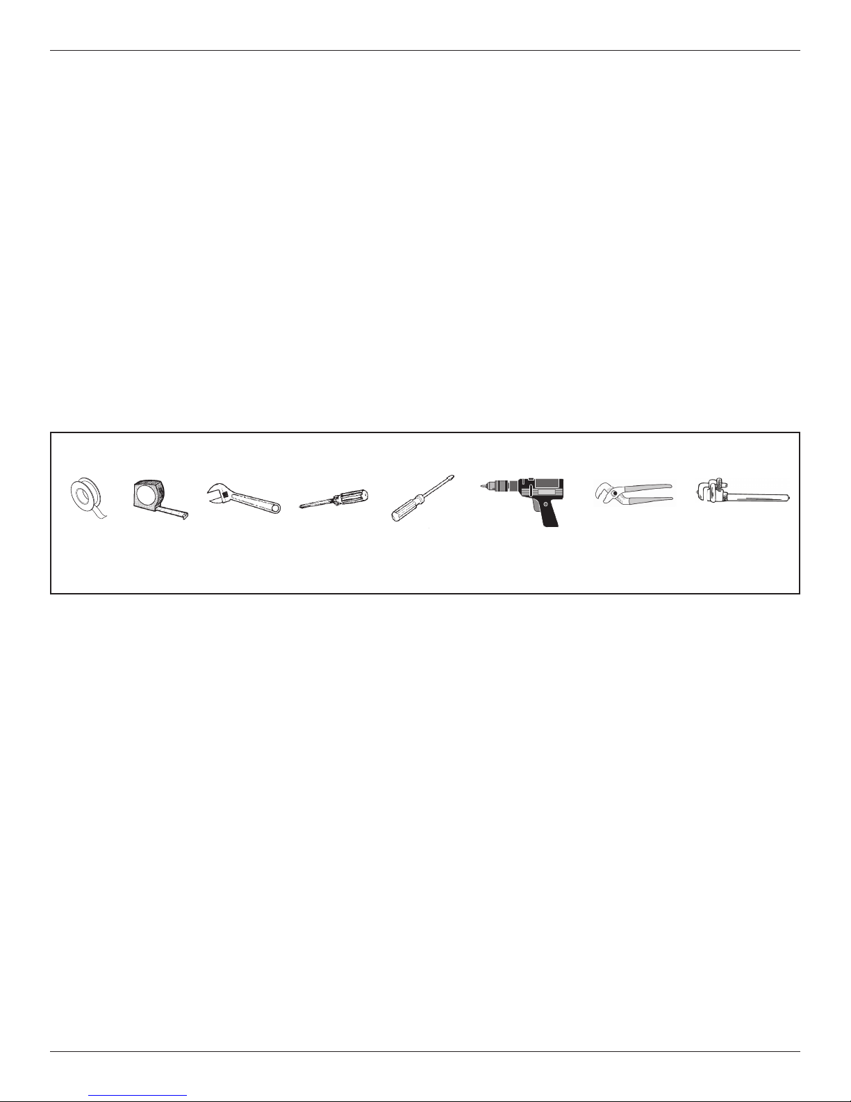
TOOLS NEEDED
Review the tools needed list. See Fig. 5. Gather needed
tools before proceeding with the installation. Read and
follow the instructions provided with any tools listed here.
Thread
Sealing
Tape
Tape
Measure
Adjustable
Wrench
Philips
Screwdriver
Screwdriver
Overview and Site Preparation
OVERVIEW
Read through the entire manual before beginning your
installation.
There are seven steps to installing your Drinking Water
system. They are as follows:
STEP A - Install Cold Water Supply Fitting
STEP B - Install Drain Adapter
STEP C - Install Reverse Osmosis Assembly
STEP D - Install Storage Tank
STEP E - Install Reverse Osmosis Faucet
STEP F - Connect Tubing
STEP G - Sanitize, Pressure Test & Purge System
These steps are explained in detail over the next few
pages. Follow all steps. Reading this manual will also
help you receive and use all the benefits your Reverse
Osmosis system can give you.
Flathead
OR
Pipe Wrench
FIG. 5
Drill & Drill Bits,
if required
Adjustable
Large Jaw
Pliers
PREPARE SITE FOR INSTALLATION
1. Before starting, close the hot and cold water shutoff
valves (See Figure 6).
2. Temporarily place tank and filter assembly into
planned location. Check position of items and space
required for proper installation. Ensure tubes may be
routed without kinking.
3. Remove tank and filter from planned location and set
aside.
NOTE: You must check and comply with all local
plumbing codes.
6
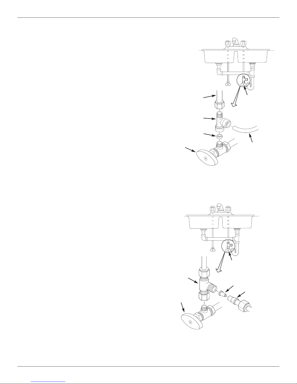
Step A - Install Supply Water Fitting
CHOOSE TYPE OF WATER FITTING TO INSTALL
heck and comply with local plumbing codes as you plan,
C
then install a cold water supply fitting. Refer to the
Specifications page for supply water requirements. The fitting
must provide a leak-tight connection to the RO 1/4" tubing. A
typical connection using the included water supply fitting is
shown in Figure 6. An optional connection using standard
plumbing fittings (not included) is shown in Figure 6B.
NOTE: Local code may dictate which type of water fitting is used. Consult a plumber if you are not familiar
with local codes or plumbing procedures.
cold water
line
Cold Water
Shutoff Valve
INSTALL COLD WATER SUPPLY FITTING
(Included)
This fitting will be installed on the cold water pipe. The fitting
must provide a leak-tight connection to the Reverse Osmosis
1/4" tubing. Locate the cold water line in the sink cabinet. It
is recommended, but not required, that the cold water line be
soft water.
Complete the following steps to install the water supply fitting.
1. Close the hot and cold water shutoff valves under the sink
where the cold water supply fitting will be installed, and
open faucet(s) to relieve pressure.
2. Disconnect the existing cold water line from the water
shutoff valve.
3. Make sure that the water supply fitting’s gasket is inside
the female threaded portion of the fitting.
4. Install the water supply fitting onto the cold water shutoff
valve, where the existing cold water line was removed,
and hand tighten. Be careful not to cross thread or overtighten.
5. Connect the existing cold water line to the male threaded
portion of the water supply fitting and hand tighten. Be
careful not to cross thread or overtighten.
water supply
fitting
gasket
cold water
shutoff
Cold Water Supply Connection
(using included water supply fitting)
1/4” green
tubing to
Reverse
Osmosis inlet
FIG. 6
OPTIONAL PIPE FITTINGS
(compression type shown)
NOTE: Be sure to turn off the water supply and open a
faucet to drain the pipe.
Complying with plumbing codes, install a fitting on the cold
water pipe to adapt 1/4" OD tubing. A typical connection is
shown in Figure 6B. If threaded fittings are used, be sure to
use pipe joint compound or thread sealing tape on outside
threads.
Cold Water
1/4”
compression
fitting
cold water
shutoff
Shutoff Valve
insert
ferrule
1/4” green
tubing to
Reverse
Osmosis inlet
Cold Water Supply Connection
(using compression fitting - not included)
FIG. 6B
7
Step B - Install RO Drain Under Sink
INTRODUCTION
A suitable drain point is needed for the drain water from
he Reverse Osmosis filter. You have two options:
t
• Install the Drain Adaptor included with your unit
As shown in Figures 7-9, the drain adaptor is
nstalled onto your sink’s drain pipe above the P-trap.
i
This is normally used for under sink installations.
• Use another existing drain in your home
As shown in Figures 10 and 11, the drain tube from
the RO filter runs directly to an open drain. This is
often used for remote location installations.
NOTE: An incorrectly connected drain point can
cause water to leak from the faucet’s air gap.
NOTE: Local code may restrict the type of drain
installation to use. Either drain installation type, if
permitted by code, may be used in under sink or
remote location installations. Consult a plumber if
you are not familiar with plumbing procedures.
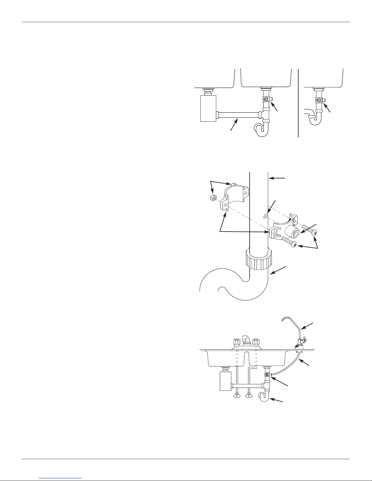
INSTALL DRAIN ADAPTOR
(Under sink Installation)
The drain adaptor included with your RO system is
designed to fit around a standard 1-1/2” O.D. drain
pipe. In the following procedure, you will install the
drain adaptor above (upstream of) the P-trap. See Fig.
7 & 9. Be sure to comply with local plumbing codes.
NOTE: Before starting this procedure, inspect the
drain pipe under the sink for corrosion, and replace
if necessary, before continuing with installation.
1. Test fit the two halves of the drain adaptor onto the
sink drain pipe, about 6 inches above the P-trap
(See Fig. 8). Make sure that the Q.C. fitting is
toward the direction of the RO faucet (See Fig. 9).
NOTE: Locate so that the drain tubing from the
Reverse Osmosis faucet will run straight to the
adaptor, with no dips, loops, or kinks.
2. Using the hole through the drain fitting as a guide,
mark the pipe where a 3/8” hole will be drilled (See
Fig. 8), and remove the drain adaptor from the pipe.
NOTE: Do not drill through the drain adaptor’s
Q.C. fitting, as this could damage the o-ring.
3. Drill a 3/8” dia. hole in the pipe and remove flash.
4. Clean the sink tailpiece to assure a leak-tight fit.
5. Place the halves of the drain fitting back onto the
sink drain pipe. Use a pencil or similar pointed
object to align the Q.C. fitting so that it is centered
on the hole you drilled.
6. Assemble the nuts and screws, as shown in Figure
9, and tighten both sides equally to secure the drain
adaptor halves onto the pipe. Do not overtighten.
7. Do not connect black tubing to the Q.C. fitting at this
time. It is done after the RO faucet is installed.
Under the Sink Installation
ingle Basin
Double Basin Sink
Garbage
Disposal
Drain
Adaptor
Do not install drain
adaptor on a line coming
from a garbage disposal
Nuts
Drain
Adaptor
Halves
COLD
HOT
IMPORTANT: Do not install drain adaptor below the P-Trap.
Locate drain adaptor so that when the black
drain tube from the Reverse Osmosis Faucet
is installed it will run straight to the adaptor,
with no dips, loops, or kinks.
P–Trap
3/8” Hole - Do not drill
through Q.C. Fitting
S
Sink
Drain
Adaptor
P–Trap
FIG. 7
Sink Drain Pipe
3/8” Quick
Connect
Fitting
Screws
P-Trap
FIG. 8
RO Faucet
Black Drain
Tube
Drain Adaptor
P–Trap
FIG. 9
8
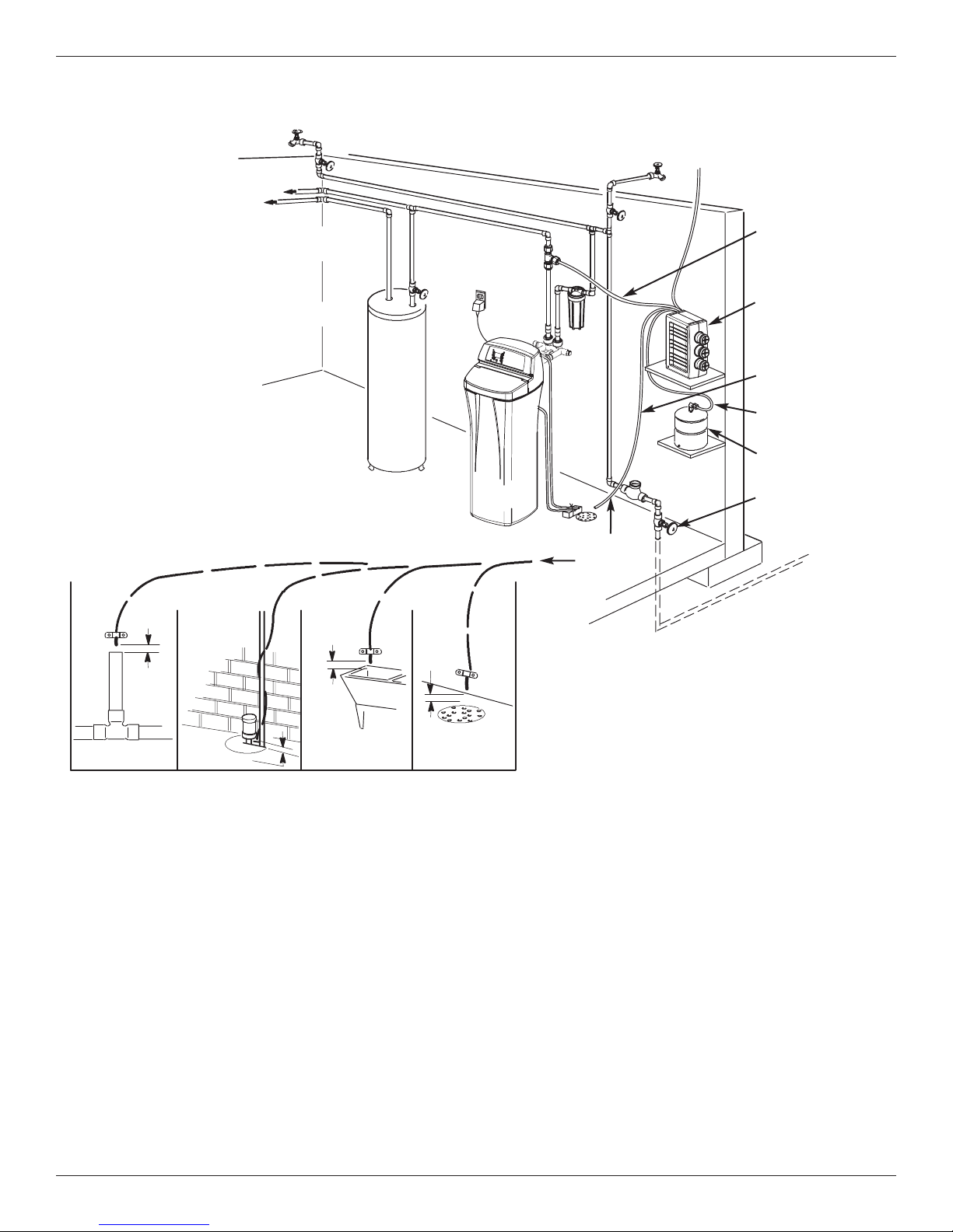
Step B - Install RO Drain in Remote Location
Outside Faucet
utside Faucet
Soft, Cold Water
Soft, Hot
Water
Remote Installation
Location
IMPORTANT: Allow adequate open
space behind the
water filtration system
to avoid sharp bends
or kinks in the tubing.
(Hard Water)
Water
Heater
O
(Hard Water)
H
a
r
d
Wa
te
r
L
in
e
Shutoff
Valve
Hard
Water to
House
Water
Softener
Water
Meter
BLUE Tubing
to Reverse
smosis Faucet
O
Soft Water -
REEN Tubing
G
to Reverse
Osmosis System
Reverse Osmosis
System
Reverse Osmosis
Drain - RED
Tubing to Drain
YELLOW Tubing
to Storage Tank
Storage Tank
Main Shutoff
Valve
1/4'' RED Tubing
1-1/2”
Air Gap
Laundry
Tub
1-1/2”
Air Gap
1-1/2”
Air Gap
Stand pipe
Sump
1-1/2”
Air Gap
INSTALL A REMOTE DRAIN POINT
AND AIR GAP (Remote Location)
Route the drain tubing to an existing drain in the house.
A floor drain, laundry tub, standpipe, sump, etc. are
suitable drain points. See Fig. 11. This type of drain is
the preferred over the p-trap drain adapter.
Always be sure to provide a 1-1/2” air gap between the
end of the hose and the drain point. This will prevent
water from backing up into the system.
NOTE: Check your local plumbing codes.
RED
Tubing to
Drain
Floor
Drain
FIG. 11
To install a remote drain point, complete the
following steps:
1. Locate the 1/4” red tubing on the Reverse Osmosis
filter assembly. See Fig. 10.
2. Determine if this length is long enough to reach the
drain point. Longer lengths of tubing (see parts list in
back of manual) may be needed.
3. If longer tubing is required, disconnect the 1/4” red
tubing and replace with an adequate length of tubing
to reach the drain point. Refer to Step F later in the
manual on how to disconnect and connect tubing.
NOTE: A flow control insert is located inside the
fitting that the drain tube connects to. See No. 12
on page 22. Leave this fitting in place.
4. Route the tubing to the drain point and secure at the
end with a bracket (not included). See Fig. 11.
Provide a 1-1/2” air gap between the end of the tube
and the drain. See Fig. 11.
FIG. 10
9
 Loading...