

Whirlpool WHP43, WGHP43, WGHP44, WGHP46, WGHP48 Installation Instructions Manual
...
HEAT PUMP INSTALLATION INSTRUCTIONS
Table of Contents
HEAT PUMP UNIT SAFETY...........................................................1
INSTALLATION REQUIREMENTS................................................ 2
Tools and Parts ............................................................................2
System Requirements..................................................................2
Location Requirements................................................................3
Electrical Requirements ...............................................................3
INSTALLATION INSTRUCTIONS..................................................4
Inspect Shipment.........................................................................4
Flush Refrigerant Lines ................................................................4
HEAT PUMP UNIT SAFETY
System Installation .......................................................................4
Connect Refrigerant Lines ...........................................................5
Make Electrical Connections .......................................................6
Charge Refrigerant Lines .............................................................8
Complete Installation..................................................................11
TROUBLESHOOTING ..................................................................12
SYSTEM MAINTENANCE ............................................................16
ASSISTANCE OR SERVICE.........................................................16
Accessories ................................................................................16
Recognize this symbol as a safety precaution.
Recognize Safety Symbols, Words and Labels
The following symbols and labels are used throughout this
manual to indicate immediate or potential hazards.It is the
owner’s responsibility to read and comply with all safety
information and instructions accompanying these symbols.
Failure to heed safety information increases the risk of serious
personal injury or death, property damage and/or product
damage.
WARNING
Hazards or unsafe practices could result in property
damage, product damage, severe personal injury or death.
Goodman 1
CAUTION
Hazards or unsafe practices may result in property
damage, product damage, personal injury or death.
CAUTION
Hazards or unsafe practices may result in property
or product damage.
Goodman 9
WARNING
Installation and repair of this unit should
be performed ONLY by individuals meeting
the requirements of an “Entry Level Technician”
as specified by the Air-Conditioning, Heating and
Refrigeration Institute (AHRI). Attempting to
install or repair this unit without such background may
result in product damage, personal injury or death.
Goodman 7
WARNING
HIGH VOLTAGE!
Disconnect ALL power before servicing.
Multiple power sources may be present.
Failure to do so may cause property damage,
personal injury or death.
Goodman 6
WARNING
Scroll equipped units should never be used to evacuate
the air conditioning system. Vacuums this low can cause
internal electrical arcing resulting in a damaged or failed
compressor.
Goodman 32
Whirlpool® and Whirlpool Gold® Models WHP43, WHP44, WGHP43, WGHP44, WGHP46 and WGHP48
WPIO-259G

IMPORTANT: The United States Environmental Protection
Agency (EPA) has issued various regulations regarding the
introduction and disposal of refrigerants in this unit. Failure to
follow these regulations may harm the environment and can lead
to the imposition of substantial fines. These regulations may vary
by jurisdiction. A certified technician must perform the installation
and service of this product. Should questions arise, contact your
local EPA office.
INSTALLATION REQUIREMENTS
These instructions are intended as a general guide only for use by
qualified persons and do not supersede any national or local
codes in any way. The installation must comply with all state and
local codes as well as the National Electrical Code.
■ The heat pump is designed and approved for outdoor use
only.
■ The heat pump must be installed with no ductwork in the
airstream. The outdoor fan is not designed to operate against
any additional static pressure.
WARNING
Goodman 12
To avoid possible injury, explosion or death, practice safe
handling of refrigerants.
WARNING
Goodman 13
Refrigerants are heavier than air. They can "push out"
the oxygen in your lungs or in any enclosed space. To
avoid possible difficulty in breathing or death:
• Never purge refrigerant into an enclosed room or
space. By law, all refrigerants must be reclaimed.
• If an indoor leak is suspected, throughly ventilate the
area before beginning work.
• Liquid refrigerant can be very cold. To avoid possible
frostbite or blindness, avoid contact and wear gloves
and goggles. If liquid refrigerant does contact your
skin or eyes, seek medical help immediately.
• Always follow EPA regulations. Never burn refrigerant,
as poisonous gas will be produced.
This product is designed and manufactured to permit installation
in accordance with national codes. It is the installer’s
responsibility to install this unit in accordance with national codes
and/or prevailing local codes and regulations.
WARNING
Goodman 15
To avoid possible explosion, use only returnable (not
disposable) service cylinders when removing refrigerant
from a system.
• Ensure the cylinder is free of damage which could lead
to a leak or explosion.
• Ensure the hydrostatic test date does not exceed 5 years.
• Ensure the pressure rating meets or exceeds 400 lbs.
When in doubt, do not use cylinder.
Tools and Parts
Gather the required tools and parts before starting installation.
Read and follow the instructions provided with any tools listed
here.
Tools Needed
■ To rc h
■ ¹⁄₄" (6.4 mm) nut driver
■ Vacuum pump
■ Micron gauge
Parts Needed
Check local codes and HVAC supplier. Check existing electrical
supply, and read “Electrical Requirements,” “Location
Requirements,” “System Requirements” and “Connect
Refrigerant Lines.”
NOTE: Some condensing units do not contain a factory-installed
filter dryer. With those units, a properly sized filter dryer must be
field installed in the liquid (high pressure) line set between the
outdoor condensing unit and indoor evaporator unit.
■ ⁵⁄₁₆" (7.6 mm) nut driver
■ Gauge set for R-410A
refrigerant
■ Nitrogen system
WARNING
Goodman 14
To avoid possible explosion:
• Never apply flame or steam to a refrigerant cylinder. If
you must heat a cylinder for faster charging, partially
immerse it in warm water.
• Never fill a cylinder more than 80% full of liquid
refrigerant.
• Never add anything other than R-22 to an R-22 cylinder
or R-410A to an R-410A cylinder. The service
equipment used must be listed or certified for the type
of refrigerant used.
• Store cylinders in a cool, dry place. Never use a cylinder
as a platform or a roller.
2
System Requirements
Heat pump system matches are derived from actual laboratory
testing of matched systems. It is recommended that only
matching equipment be used to ensure proper operation and
efficient performance.
■ The designed system matches are listed in the heat pump
specification sheets and on the heat pump refrigerant
charging instructions located on the back of the service
access panel.
■ Refrigerant charging instructions include a list of matching
indoor equipment with the proper thermal expansion device
size and amount of refrigerant charge required.
■ This heat pump has been factory charged with a quantity of
refrigerant (R-410A) sufficient for a matched indoor coil and a
maximum 15 ft (4.6 m) of refrigerant line.
Indoor System Thermal Expansion Device
■ Check the indoor coil thermal expansion device to see
whether it matches the required thermal expansion device for
the indoor coil and heat pump combination being installed.
■ Refer to the refrigerant charge label located on the inside of
the heat pump access panel for the correct thermal
expansion device size required.
■ Replace the thermal expansion device with the correct size if
this size is not already installed in the indoor coil. Instructions
for replacing the thermal expansion device are provided with
the indoor coil.
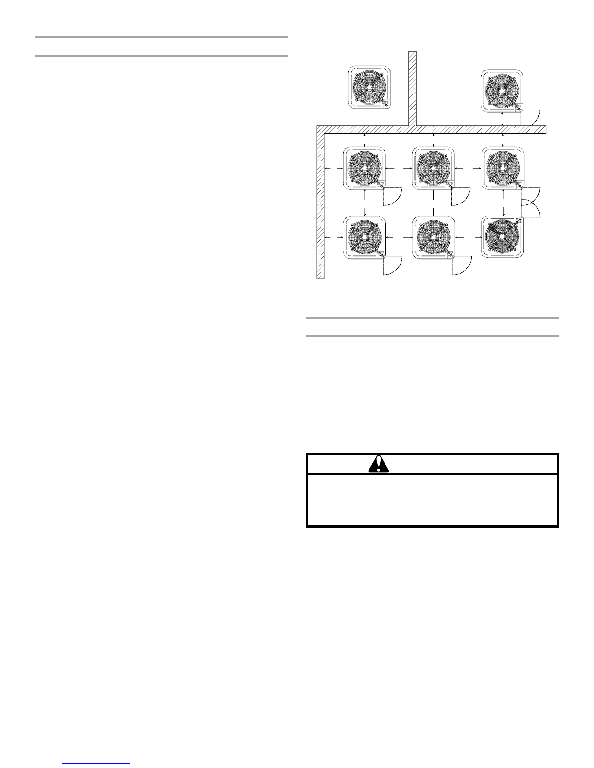
Installation Clearances—Single or Multiple Unit Installation
A
B
B
D D
B B
C
B
OK!
Location Requirements
■ This heat pump is designed to be located outdoors with
sufficient clearance for free entrance to the inlet and
discharge air openings. The location must also allow for
adequate service access. See “Installation Clearances.”
■ Where possible, select a location for the heat pump which is
shaded from the direct rays of the sun most of the time. North
or east locations are usually most desirable. Position the heat
pump to avoid direct contact with water, snow or ice from a
roofline overhead.
■ The heat pump must be installed on a solid, level mounting
pad that will not settle or shift. Isolate the pad from the
building structure to avoid possible transmission of sound or
vibration from the heat pump into the conditioned space.
■ The heat pump foundation should be raised to a minimum of
3" (7.6 cm) above finish grade. In areas which have prolonged
periods of temperatures below freezing, and/or snowfall, the
heat pump should be elevated above the average snow line.
If heat pump is to be installed on a flat roof, it should be on a
platform or other support which will raise the inlet air opening
12" (30.5 cm) minimum above the surface of the flat roof.
■ Avoid ice accumulation by ensuring free drainage of
condensate from defrost cycles. The heat pump should be
located away from walkways to avoid possible icing from
defrost condensate.
■ Avoid placing the heat pump near areas such as sleeping
quarters or study rooms. Normal operating sound levels may
be objectionable if the heat pump is placed near certain
rooms. A shift in sound type does occur during the defrost
mode. The defrost mode generally lasts no longer than
10 minutes.
■ Where possible, the top of the condensing unit should be
completely unobstructed.
■ If vertical conditions require placement beneath an
obstruction, there should be a minimum of 5 ft (1.5 m)
between the top of the condensing unit and the obstruction.
NOTE: The specified dimensions meet requirements for air
circulation only. Consult all appropriate regulatory codes prior
to determining final clearances.
■ Avoid corner installations if possible.
■ Either side adjacent to the valves can be placed toward the
structure provided the side away from the structure maintains
minimum service clearance.
C
D
B
D
C
D
D
C
D
OK!
OK!
C
CC
A. Not recommended
B. 10" (25.4 cm)
C. 18" (45.7 cm)
D. 20" (50.8 cm)
Rooftop Installation
■ Check that the roof structure can support the weight of the
condensing unit.
■ Keep the weather-tight integrity of the roof during and after
installation.
■ Vibration-absorbing pads or springs can be installed between
the condensing unit legs or frame and the roof mounting
assembly to reduce noise vibration.
Electrical Requirements
WARNING
To avoid the risk of injury, electrical shock or death, the
furnace must be electrically grounded in accordance with
local codes or, in their absence, with the latest edition of the
National Electric Code (NEC).
IMPORTANT: The United States Environmental Protection
Agency (EPA) has issued various regulations regarding the
introduction and disposal of refrigerants in this unit. Failure to
follow these regulations may harm the environment and can lead
to the imposition of substantial fines. These regulations may vary
by jurisdiction. A certified technician must perform the installation
and service of this product. Should questions arise, contact your
local EPA office.
This product is designed and manufactured to permit installation
in accordance with national codes. It is the installer’s
responsibility to install this unit in accordance with national codes
and/or prevailing local codes and regulations.
Goodman 31
3
NOTE: All outdoor wiring must be suitable for outdoor use. Use
copper conductors only.
■ All field wiring must be done in accordance with National
Electrical Code requirements, applicable requirements of UL,
or local codes, where applicable.
INSTALLATION INSTRUCTIONS
■ Electrical wiring, disconnect means and over-current
protection are to be supplied by the installer. Refer to the
rating plate for the maximum over-current protection,
minimum circuit ampacity, and operating voltage. See the
wiring diagrams in “Make Electrical Connections.”
Inspect Shipment
This heat pump is shipped in one package, completely
assembled and wired. The thermostat is shipped in a separate
carton when ordered.
■ Check the heat pump rating plate to confirm specifications
are as ordered.
■ Upon receipt of equipment, inspect it for possible shipping
damage. Examine the heat pump inside the carton if the
carton is damaged.
■ If damage is found, it should be noted on the carrier’s freight
bill. Damage claims should be filed with the carrier
immediately. Claims of shortages should be filed with the
seller within 5 days.
NOTE: If any damages are discovered and reported to the carrier,
do not install the heat pump, because your claim may be denied.
Flush Refrigerant Lines
Refrigerant lines must be flushed by a licensed, EPA certified
refrigerant technician in accordance with established procedures.
NOTES:
■ R-410A outdoor systems are not recommended for use with
indoor systems that have used R-22 as the refrigerant.
However, if this condensing unit is being matched with an
approved line set which was previously charged with R-22
refrigerant, the line set must be flushed prior to installation.
See your local distributor for an appropriate flushing kit.
■ Check the refrigerant lines for size and length. See “Connect
Refrigerant Lines.”
■ Polyol ester (POE) oils are used in Whirlpool units charged
with R-410A refrigerant. Residual mineral oil from the R-22
system can act as an insulator, inhibiting proper heat transfer.
It can also clog the thermal expansion device, reducing
system performance and capacity.
■ Where possible, drain as much residual compressor oil from
the existing systems, lines, and traps. Pay close attention to
low areas where oil may collect.
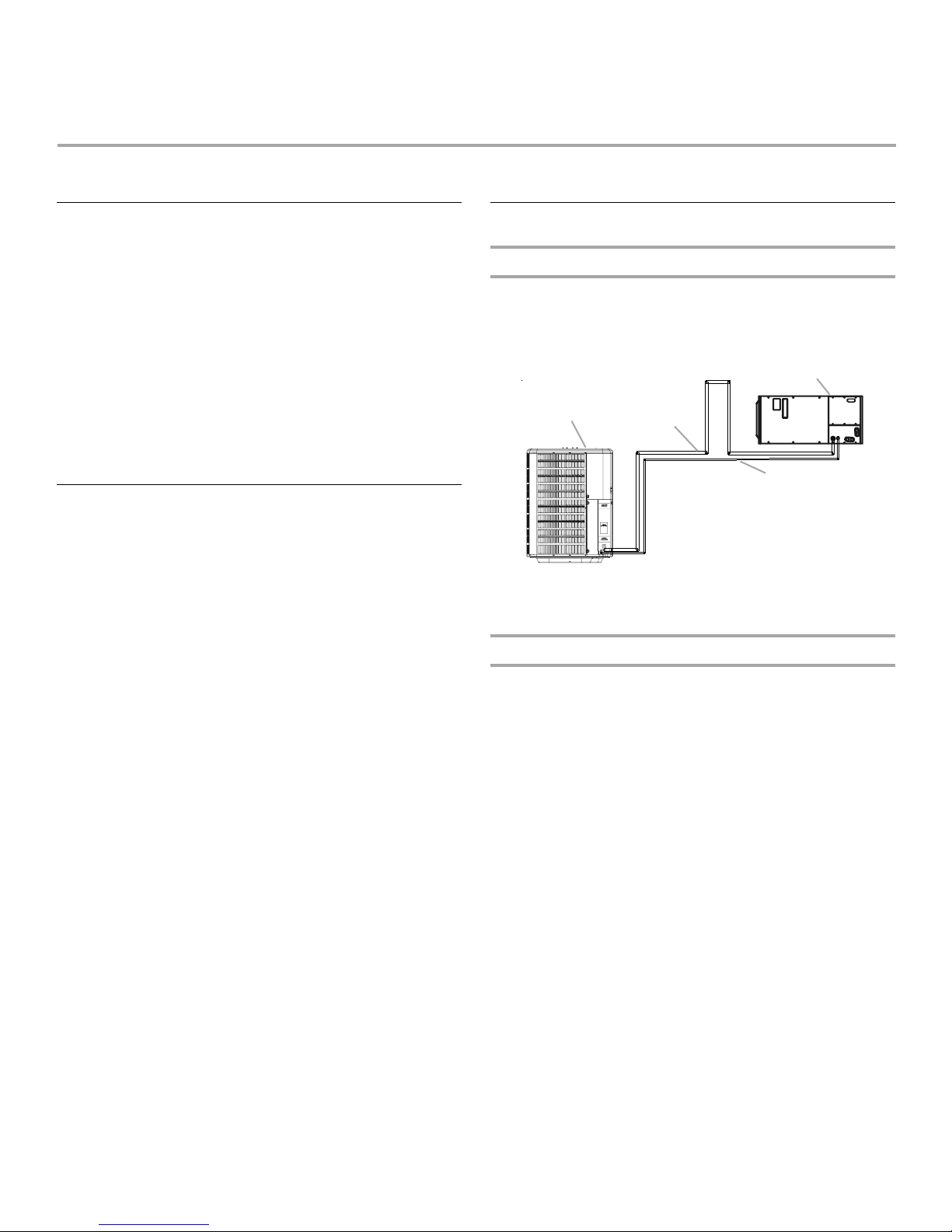
System Installation
Mounting Evaporator Coil Above Condensing Unit
When mounting the evaporator coil above the condensing unit,
an inverted loop in the suction line adjacent or near the
connection to the evaporator coil is required. The top of the loop
must be slightly higher than the top of the evaporator coil.
C
A
A. Condensing unit
B. Suction line
Mounting Condensing Unit Below Evaporator Coil
When mounting the condensing unit above the evaporator coil,
oil traps are required at equal intervals along the suction line.
■ Install 1 oil trap for a height difference of 15 ft to 25 ft (4.6 m
to 7.6 m) between indoor and outdoor units.
■ Install 2 oil traps for a height difference of 26 ft to 50 ft (7.9 m
to 15.2 m) between indoor and outdoor units.
■ Install 3 oil traps for a height difference of 51 ft to 100 ft
(15.5 m to 30.5 m) between indoor and outdoor units.
B
D
C. Evaporator coil
D. Liquid line
4
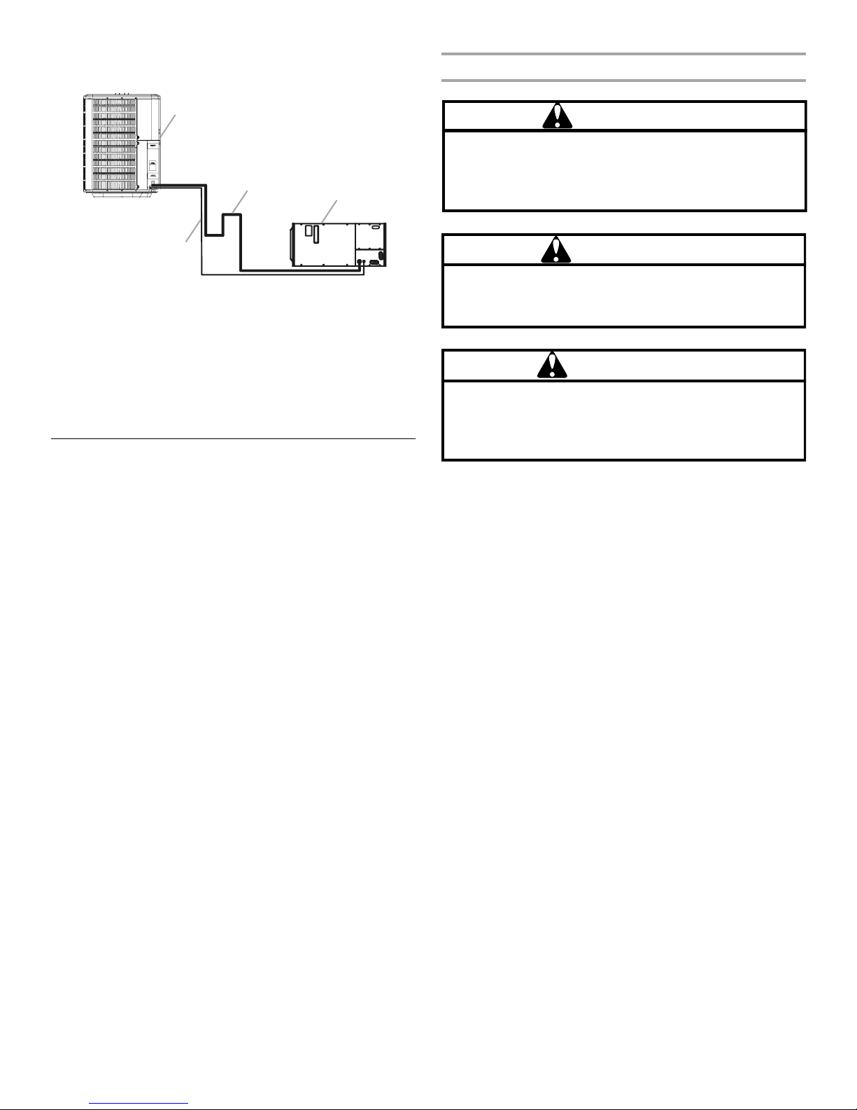
■ Install 4 oil traps for a height difference of 101 ft to 150 ft
(30.8 m to 45.7 m) between indoor and outdoor units.
Connect Liquid and Suction Lines
A
C
B
A. Condensing unit
B. Liquid line
Insulation is necessary to avoid condensation from forming and
dropping from the suction line. Armflex (or satisfactory
equivalent) with ³⁄₈" (1 cm) minimum wall thickness is
recommended. In severe conditions (hot, high humidity areas),
¹⁄₂" (1.3 cm) insulation may be required. Insulation must be
installed in a manner which keeps tubing from damage and
contamination.
C. Suction line
D. Evaporator coil
D
Connect Refrigerant Lines
Refrigerant lines must be connected by a licensed, EPA certified
refrigerant technician in accordance with established procedures.
IMPORTANT:
■ Connecting refrigerant lines must be clean, dehydrated,
refrigerant-grade copper lines. Heat pumps should be
installed only with specified line sizes for approved system
combinations with elevation differences up to 15 ft (4.6 m)
and total length of up to 50 ft (15.2 m). See the Suction Line
Sizes and Liquid Line Sizes charts.
■ Sharp bends or possible kinking in the lines will cause a
reduction in performance.
■ To avoid contamination of the refrigerant system, do not
remove the caps from the lines or system connection points
until connections are ready to be completed.
CAUTION
Goodman 16
The compressor POE oil for R-410A units is extremely
susceptible to moisture absorption and could cause
compressor failure. Do not leave system open to
atmosphere any longer than necessary for installation.
Goodman 17
WARNING
To avoid the risk of fire or explosion, never use oxygen,
high pressure air or flammable gases for leak testing of a
refrigeration system.
WARNING
Goodman 18
To avoid possible explosion, the line from the nitrogen
cylinder must include a pressure regulator and a pressure
relief valve. The pressure relief valve must be set to open at
no more than 150 psig.
1. Route the suction and liquid lines from the fittings on the
indoor coil to the fittings on the heat pump. Run the lines in
as direct a path as possible, avoiding unnecessary turns and
bends.
2. For product efficiency, be sure that the suction line is
insulated over the entire exposed length and that both
suction and liquid lines are not in direct contact with floors,
walls, ductwork, floor joists, or other piping.
3. Remove valve cores.
4. Wrap the service valves with a wet rag or an approved
thermal trap.
5. If a filter dryer is not provided, install a filter dryer in the liquid
line between the outdoor condensing unit and the indoor
evaporator coil.
NOTE: To reduce oxidation from forming and contaminating
the system, purge the line set/coil with nitrogen (1 to 2 psig)
during the brazing process.
5
 Loading...