

Whirlpool WGGE45 Installation Instructions Manual
PACKAGE GAS ELECTRIC FURNACES
INSTALLATION INSTRUCTIONS
Table of Contents
GAS FURNACE SAFETY................................................................1
INSTALLATION REQUIREMENTS................................................4
Tools and Parts ............................................................................4
Location Requirements................................................................4
Ductwork Requirements ..............................................................6
Filter Requirements......................................................................6
Electrical Requirements ...............................................................7
Gas Supply Requirements...........................................................7
INSTALLATION INSTRUCTIONS..................................................7
Inspect Shipment.........................................................................7
Place Unit in Final Location .........................................................7
Airflow Conversion .......................................................................7
Hood Installation ..........................................................................8
Connect Condensate Drain .........................................................8
Install Ductwork............................................................................8
Make Electrical Connections .......................................................9
Make Gas Connections..............................................................10
Start-up, Adjustments and Checks ...........................................14
Gas Manifold Pressure Measurement and Adjustment.............15
Blower Speed Adjustments........................................................17
Blower Performance Data..........................................................17
Unit Shutdown............................................................................19
Cooling Start-Up ........................................................................19
SEQUENCE OF OPERATION ......................................................20
Heating System ..........................................................................20
Cooling System ..........................................................................20
Fan Only .....................................................................................21
Cooling Start-Up ........................................................................21
MAINTENANCE ............................................................................22
TROUBLESHOOTING ..................................................................23
Unit Fails to Operate Properly....................................................23
Ignition Control Error Codes ......................................................23
Abnormal Operation—Heating...................................................24
Abnormal Operation—Cooling...................................................25
ASSISTANCE OR SERVICE.........................................................28
Accessories ................................................................................28
GAS FURNACE SAFETY
Recognize this symbol as a safety precaution.
Please adhere to the following warnings and cautions when installing, adjusting, altering, servicing or operating the furnace.
WARNING
Hazards or unsafe practices could result in property
damage, product damage, severe personal injury or death.
Goodman 1
CAUTION
Hazards or unsafe practices may result in property
damage, product damage, personal injury or death.
Placeholder
for
Bar
Code
Whirlpool Gold® Models
WGGE45
Whirlpool® Home Cooling and Heating
14610 Breakers Drive
Jacksonville, FL 32258
Hazards or unsafe practices may result in property
or product damage.
CAUTION
Goodman 9
WPIO-325C
IMPORTANT SAFETY INSTRUCTIONS
Use only with type of gas approved for this furnace.
■
Refer to the furnace rating plate.
Install this furnace only in a location and position
■
as specified in the “Location Requirements” section
of these instructions.
Provide adequate combustion and ventilation air to
■
the furnace space as specified in the “Venting
Requirements” section of these instructions.
■
Combustion products must be discharged outdoors.
Connect this furnace to an approved vent system
only, as specified in the “Venting Requirements”
section of these instructions.
Never test for gas leaks with an open flame. Use a
■
commercially available soap solution made
specifically for the detection of leaks to check all
connections, as specified in the “Make Gas
Connections” section of these instructions.
Adequate clearance must be provided around the
■
vent-air intake terminals.
ANSI Box Install G 2009 in Goodman Folder
Always install furnace to operate within the furnace’s
■
intended temperature-rise range with a duct system
which has an external static pressure within the
allowable range, as specified in the “Complete
Installation” section of these instructions. See
furnace rating plate.
■
When a furnace is installed so that supply ducts
carry air circulated by the furnace to areas outside
the space containing the furnace, the return air
shall also be handled by duct(s) sealed to the
furnace casing and terminating outside the space
containing the furnace.
A gas-fired furnace for installation in a residential
■
garage must be installed as specified in the
“Location Requirements” section of these
instructions.
The furnace shall be installed so the electrical
■
components are protected from water.
■ Furnaces for indoor installation on combustible
flooring shall not be installed directly on carpeting,
tile or other combustible material other than wood
flooring.
SAVE THESE INSTRUCTIONS
To the Installer
Before installing this unit, please read this manual thoroughly to
familiarize yourself with specific items which must be adhered to,
including but not limited to: unit maximum external static
pressure, gas pressures, Btu imput rating, proper electrical
connections, circulating air temperature rise, minimum or
maximum CFM and motor speed connections and venting.
These furnaces are designed for Category I venting only.
WARNING
If the information in these instructions is not followed
exactly, a fire or explosion may result causing property
damage, personal injury or loss of life.
— Do not store or use gasoline or other flammable vapors
and liquids in the vicinity of this or any other appliance.
— WHAT TO DO IF YOU SMELL GAS
• Do not try to light any appliance.
• Do not touch any electrical switch; do not use any phone
in your building.
• Immediately call your gas supplier from a neighbor’s
phone. Follow the gas supplier’s instructions.
• If you cannot reach your gas supplier, call the fire
department.
— Installation and service must be performed by a
qualified installer, service agency or the gas supplier.
Goodman 42
WARNING
Should overheating occur or the gas supply fail to shut
off, turn off the manual gas shutoff valve external to the
furnace before turning off the electrical supply.
Goodman 43
WARNING
Do not connect to or use any device that is not designcertified for use with this unit. Serious property damage,
personal injury, reduced unit performance and/or hazardous
conditions may result from the use of such non-approved
devices.
Goodman 36
WARNING
This product contains or produces a chemical or
chemicals which may cause serious illness or death and
which are known to the State of California to cause
cancer, birth defects or other reproductive harm.
Goodman 45
2
WARNING
WARNING
Heating unit should not be utilized without reasonable,
routine inspection, maintenance and supervision. If the
building in which any such device is located will be
vacant, care should be taken that such device is
routinely inspected, maintained and monitored. In the
event that the building may be exposed to freezing
temperatures and will be vacant, all water-bearing pipes
should be drained, the building should be properly
winterized and the water source closed. In the event
that the building may be exposed to freezing
temperatures and will be vacant, any hydronic coil units
should be drained as well, and, in such case, alternative
heat sources should be utilized.
Goodman 47
WARNING
To avoid property damage, personal injury or death, do
not use this furnace if any part of the furnace has been
under water. Immediately call a qualified service technician
to inspect the furnace and to replace any part of the
control system and any gas control having been under
water.
Goodman 81
WARNING
This unit must not be used as a “construction heater”
during the finishing phases of construction on a new
structure. This type of use may result in premature failure
of the unit due to extremely low return air temperatures
and exposure to corrosive or very dirty atmospheres.
Goodman 79
WARNING
HIGH VOLTAGE!
Goodman 6
Disconnect ALL power before servicing.
Multiple power sources may be present.
Failure to do so may cause property damage,
personal injury or death.
To prevent the risk of property damage, personal injury, or
death, do not store combustible materials or use gasoline
or other flammable liquids or vapors in the vicinity of this
unit.
Goodman 37
WARNING
Installation and repair of this unit should
be performed ONLY by individuals meeting
the requirements of an “Entry Level Technician”
as specified by the Air-Conditioning, Heating and
Refrigeration Institute (AHRI). Attempting to
install or repair this unit without such background may
result in product damage, personal injury or death.
Goodman 7
DANGER
Goodman 38
CARBON MONOXIDE POISONING HAZARD
Special Warning for Installation of Furnace or Air Handling
Units in Enclosed Areas such as Garages, Utility Rooms or
Parking Areas.
Carbon monoxide producing devices (such as an
automobile, space heater, gas water heater, etc.) should
not be operated in enclosed areas such as unventilated
garages, utility rooms or parking areas because of the
danger of carbon monoxide (CO) poisoning resulting from
the exhaust emissions. If a furnace or air handler is
installed in an enclosed area such as a garage, utility room
or parking area and a carbon monoxide producing device is
operated therein, there must be adequate, direct outside
ventilation.
This ventilation is necessary to avoid the danger of CO
poisoning which can occur if a carbon monoxide producing
device continues to operate in the enclosed area. Carbon
monoxide emissions can be (re)circulated throughout the
structure if the furnace or air handler is operating in any
mode.
CO can cause serious illness including permanent brain
damage or death.
3

INSTALLATION REQUIREMENTS
WARNING
To prevent property damage, personal injury or death,
due to fire, explosions, smoke, soot, condensation,
electric shock or carbon monoxide, this unit must be
properly installed, repaired, operated and maintained.
These instructions are intended as a general guide only for use by
qualified persons and do not supersede any national or local
codes in any way. Compliance with all local, state, or national
codes pertaining to this type of equipment should be determined
prior to installation.
Read this entire instruction manual, as well as the instructions
supplied in separate equipment, before starting the installation.
The installation of the unit, wiring, warm air ducts, venting, etc.
must conform to the requirements of the National Fire Protection
Association; the National Fuel Gas Code, ANSI Z223.1/NFPA No.
54 (latest edition) and the National Electrical Code, ANSI/NFPA
No. 70 (latest edition) in the United States, and any state laws,
local ordinances (including plumbing or wastewater codes), or
local gas utility requirements. Local authorities having jurisdiction
should be consulted before installation is made. Such applicable
regulations or requirements take precedence over the general
instructions in this manual.
Tools and Parts
Gather the required tools before starting installation. Read and
follow the instructions provided with any tools listed here.
Tools Needed
■ Pipe wrench
■ Screwdriver
■ Tape measure
■ Thread sealant
■ Noncorrosive leak detection solution
■ Test gau ge wi th ¹⁄₈" NPT connection
(for measuring gas supply pressure)
■ To avoid possible corrosion of the heat exchanger, do not
locate the unit in an area where the outdoor air (for example,
combustion air for the unit) will be frequently contaminated by
compounds containing chlorine or fluorine. Common sources
of such compounds include swimming pool chemicals and
chlorine bleaches, paint stripper, adhesives, paints,
varnishes, sealers, waxes (which are not yet dried) and
solvents used during construction and remodeling. Various
commercial and industrial processes may also be sources of
chlorine/fluorine compounds.
■ To avoid possible illness or death of the building occupants,
do not locate outside air intake device (economizer, manual
fresh air intake, motorized fresh air intake) too close to an
exhaust outlet, gas vent termination or plumbing vent outlet.
For specific distances required, consult local codes.
■ Allow minimum clearances from the enclosure for fire
protection, proper operation, and service access. These
clearances must be permanently maintained.
■ The combustion air inlet and flue outlet hoods on the unit
must never be obstructed. If used, do not allow the
economizer/manual fresh air damper/ motorized fresh air
damper to become blocked by snow or debris. In some
climates or locations, it may be necessary to elevate the unit
to avoid these problems.
■ When the unit is heating, the temperature of the return air
entering the unit must be between 50°F and 100°F (10ºC and
37.8ºC).
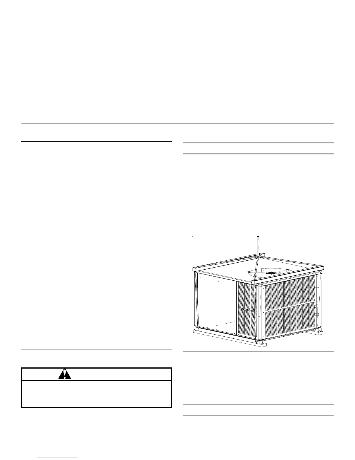
Ground Level Installations Only
■ When the unit is installed on the ground adjacent to the
building, a level concrete (or equal) base is recommended.
Prepare a base that is 3" (7.6 cm) larger than the package unit
footprint and a minimum of 3" (7.6 cm) thick.
■ The base should also be located where no runoff of water
from higher ground can collect in the unit.
Parts Needed
Check local codes and with gas supplier. Check existing gas
supply, electrical supply, and venting, and read “Ductwork
Requirements,” “Electrical Requirements” and “Gas Supply
Requirements” before purchasing parts.
Location Requirements
All Installations
WARNING
To prevent possible equipment damage, property damage,
personal injury or death, the following bullet points must
be observed when installing the unit.
■ For proper flame pattern within the heat exchanger and
proper condensate drainage, the unit must be mounted level.
■ The flue outlet hood must be at least 12" (30.5 cm) from any
opening through which flue gases could enter a building, and
at least 36" (91.4 cm) above any forced air inlet located within
10 ft (3 m). The economizer/manual fresh air intake/motorized
fresh air intake and combustion air inlet mounted on the unit
are not affected by this restriction.
Goodman 50
Rooftop Installations Only
■ The roof must have sufficient structural strength to carry the
weight of the unit(s) and snow or water loads as required by
local codes. Consult a structural engineer to determine the
weight capabilities of the roof.
Rooftop Installation
4
■ The unit may be installed directly on wood floors or on Class
A, Class B, or Class C roof covering material.
■ A safe, flat surface for service personnel should be provided.
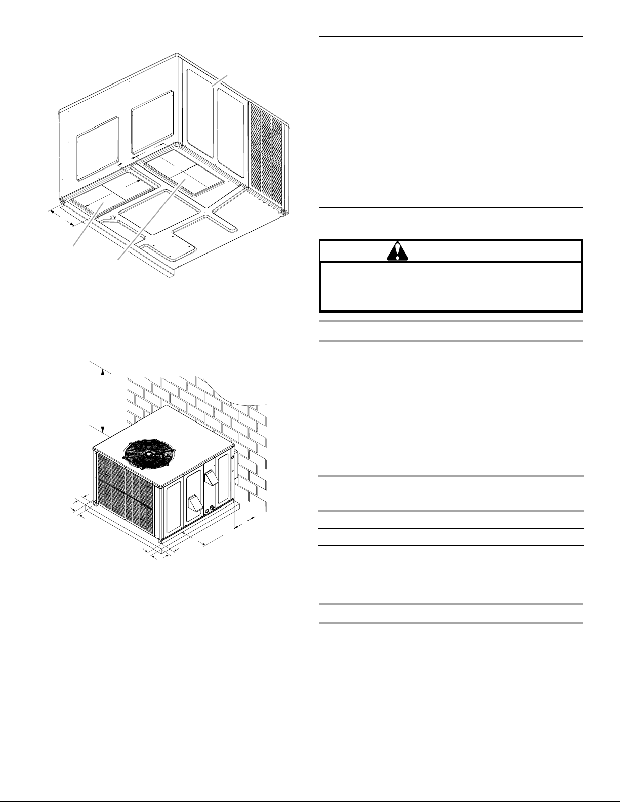
Unit Dimensions—Rear
Roof Curb Installations Only
■ Sufficient structural support must be determined prior to
locating and mounting the curb and package unit.
■ Ductwork must be constructed using industry guidelines. The
ductwork must be placed into the roof curb before mounting
the package unit.
■ Curb insulation, cant strips, flashing and general roofing
material are furnished by the contractor.
Roof Curb Installation
A
X
W
V
U
T
S
A. 47" (119.4 cm)
B. 51" (129.5 cm)
C. 18
⁷⁄₁₆
" (46.8 cm)
¹⁄₂
D. Medium: 9
(24.2 cm), large: 14"
(35.6 cm)
E. 7
¹⁵⁄₁₆
F. 16" (40.6 cm)
³⁄₈
" (3.5 cm)
G. 1
H. 5
¹⁄₂
" (14 cm)
I. Medium: 32" (81.3 cm ),
large: 40" (101.6 cm)
"
" (20.2 cm)
C
D
E
L
R
P
Q
³⁄₄
" (7 cm)
J. 2
K. Air return
L. Medium: 16"
(40.6 cm), large:
18" (45.7 cm)
M. Air supply
N. 3" (7.6 cm)
O. Evaporator/
control panel
access panel
P. 1 6
¹⁄₈
" (40.9 cm)
¹⁄₈
" (48.6 cm)
Q. 19
B
H
G
F
L
M
N
O
³⁄₄
" (12.1 cm)
R. 4
S. Gas supply entrance
T. Condensate drain
connection—
(1.9 cm) NPT female
U. Heat exchange
access panel
V. Flue exhaust hood
W. Combustion air inlet
X. Suction/liquid
pressure ports
behind compressor
access panel
I
F
J
K
³⁄₄
"
Unit Dimensions—Side
A. Center of gravity
B. 20" (50.8 cm)
C. 24" (61 cm)
D. Power supply wire
entrance
E. 7
F. 7
G. Control wire entrance
H. Flue exhaust hood
C
⁵⁄₁₆
" (17.6 cm)
⁷⁄₈
" (30 cm)
A
D
E
B
F
G
J
H
I
K
I. Control access
panel
¹⁄₄
" (13.3 cm)
J. 5
K. Combustion air
intake
5
Unit Dimensions—Inside
F
B
Ductwork Requirements
A
E
B
■ Install all conditioned air plenums, ducts and air filters (if not
provided on the unit) in accordance with NFPA 90B Standard
for the Installation of Warm Air Heating and Air-Conditioning
Systems (latest edition).
■ The unit is provided with flanges for the connection of the
plenum and ducts.
■ All air filters must be listed as Class 2 furnace air filters.
■ All ductwork must be made of materials and insulated to
meet local, state and national codes. Ductwork installed
outdoors must be sealed and be weatherproof to avoid
physical damage. Caulking, flashing or other means of
adequately providing a permanent weather seal should be
used where duct penetrates a building or structure opening.
E
D
C
A. Blower access panel
B. 22" (55.9 cm)
C. Air return
D. Air supply
E. 11" (27.9 cm)
F. 5
³₄
" (14.6 cm)
Minimum Clearances
NOTE: Roof overhang should be no more than 36" (91.4 cm).
A
B
D
C
B
A. 48" (121.9 cm) minimum
B. 12" (30.5 cm) minimum
C. 36" (91.4 cm) minimum service access
D. 3" (7.6 cm) minimum
Filter Requirements
CAUTION
To prevent property damage due to fire and loss of
equipment efficiency or equipment damage due to dust
and lint build up on internal parts, never operate unit
without an air filter installed in the return air system.
Filters
Filters are not supplied with these units; however, filters must be
used. It is the installer’s responsibility to install a filter rack with
the ductwork and to install properly sized filters in accordance
with the Minimum Required Surface Area for Disposable Filters
chart.
All return air must pass through a filter before entering the unit.
An electronic air cleaner, filter rack or other accessible filter
arrangement must be installed in the return air ductwork.
Minimum recommended filter areas are listed in the Minimum
Required Surface Area for Disposable Filters chart, and are
based on a face velocity of 325 ft (99.1 m) per min. for disposable
filters and 525 ft (160 m) per min. for cleanable filters
Filter Sizes
Unit Minimum Filter Size
2 ton 20 x 20 x 1 (1)
2.5 ton 20 x 25 x 1 (1)
3 ton 25 x 25 x 1 (1)
3.5 to 4 ton 20 x 20 x 1 (2)
5 ton 20 x 25 x 1 (2)
Goodman 93
6
Filter Installation
IMPORTANT: When installing a filter, the airflow arrows on the
filter must point toward the circulator blower.
Electrical Requirements
NOTE: All outdoor wiring must be suitable for outdoor use. Use
copper conductors only.
■ All field wiring must be done in accordance with National
Electrical Code requirements, applicable requirements of UL,
or local codes, where applicable.
■ Electrical wiring, disconnect means and over-current
protection are to be supplied by the installer. Refer to the
rating plate for the maximum over-current protection,
minimum service ampacity, and operating voltage. See the
wiring connection diagrams in “Troubleshooting.”
■ This unit must be electrically grounded in accordance with
National Electric Code (ANSI/NFPA 70) requirements,
applicable requirements of UL, or local codes, where
applicable.
INSTALLATION INSTRUCTIONS
Gas Supply Requirements
This unit is equipped for use with Natural gas. A conversion kit is
required for use with propane. To order the correct conversion kit,
see your local distributor.
■ Gas supply piping should be installed in accordance with
local, state and national codes and the regulations of the
utility. Piping must be of adequate size to prevent undue
pressure drop. Consult the local utility or gas supplier for
complete details on special requirements for sizing gas
piping.
■ If local codes allow the use of a flexible gas appliance
connector, use a CSA design-certified outdoor flexible
stainless steel appliance connector or rigid gas supply line as
needed.
Inspect Shipment
Check the carton upon arrival for external damage. If damage is
found, a request for an inspection by the carrier agent should be
made in writing immediately.
Inspect the unit for damage including damage to the cabinetry.
Any bolts or screws which may have loosened in transit must be
retightened.
In the event of damage, the receiver should:
■ Make a notation on the delivery receipt of any visible damage
to the shipment or container.
■ Notify the carrier promptly and request an inspection.
■ In case of concealed damage, the carrier should be notified
as soon as possible—preferably within 5 days.
■ File the claim with the following supporting documents:
a) Original Bill of Lading, certified copy, or indemnity bond.
b) Original paid freight bill or indemnity in lieu thereof.
c) Original invoice or certified copy thereof, showing trade
and other discounts or reductions.
d) Copy of the inspection report issued by the carrier
representative at the time damage is reported to the
carrier. The carrier is responsible for making a prompt
inspection of the damage and for a thorough investigation
of each claim. The distributor or manufacturer will not
accept claims from dealers for transportation damage.
NOTES:
■ When inspecting the unit for transportation damage, remove
all packaging materials.
■ Recycle/dispose of the packaging material according to local
codes
■ If any damages are discovered and reported to the carrier, do
not install this unit, because your claim may be denied.
Hoisting
IMPORTANT: If using the bottom discharge with the roof curb,
the ductwork should be attached to the curb prior to installing the
unit. Ductwork dimensions are shown in the roof curb installation
instructions.
See “Roof Curb Installations Only” in “Location Requirements”
for the proper curb installation. Curbing must be installed in
compliance with the National Roofing Contractors Association
Manual.
Lower the unit onto the roof mounting curb. While rigging the
unit, the center of gravity will cause the condenser end to be
lower than the supply air end.
Rigging
Place Unit in Final Location
WARNING
To prevent property damage, the unit should remain in an
upright position during all rigging and moving operations.
To facilitate lifting and moving when a crane is used,
place the unit in an adequate cable sling.
IMPORTANT: Place the unit in the final location and position it in
the proper orientation to the house so that connecting ducts,
electrical and gas supplies is easily done. Hoisting may be
required.
Goodman 88
Airflow Conversion
Units can easily be converted from horizontal to downflow airflow
delivery. In downflow or high-static installations, the installer
should measure the total external static and review the blower
performance charts before performing the installation. In some
installations, it will be necessary to change the blower speed to
provide proper airflow.
Horizontal Application
This unit is shipped ready for horizontal application.
7
Downflow Application
C
Install Combustion Air Intake Hood
For downflow applications, horizontal supply and return duct
cover kits must be ordered from your distributor. Kit number
20464501PDGK is for the medium chassis and kit number
20464502PDGK is for the large chassis.
Cut insulation around the bottom openings and remove the
panels from the bottom of the unit, saving the screws holding the
panels in place.
B
A
A. Return air panel
B. Supply air panel
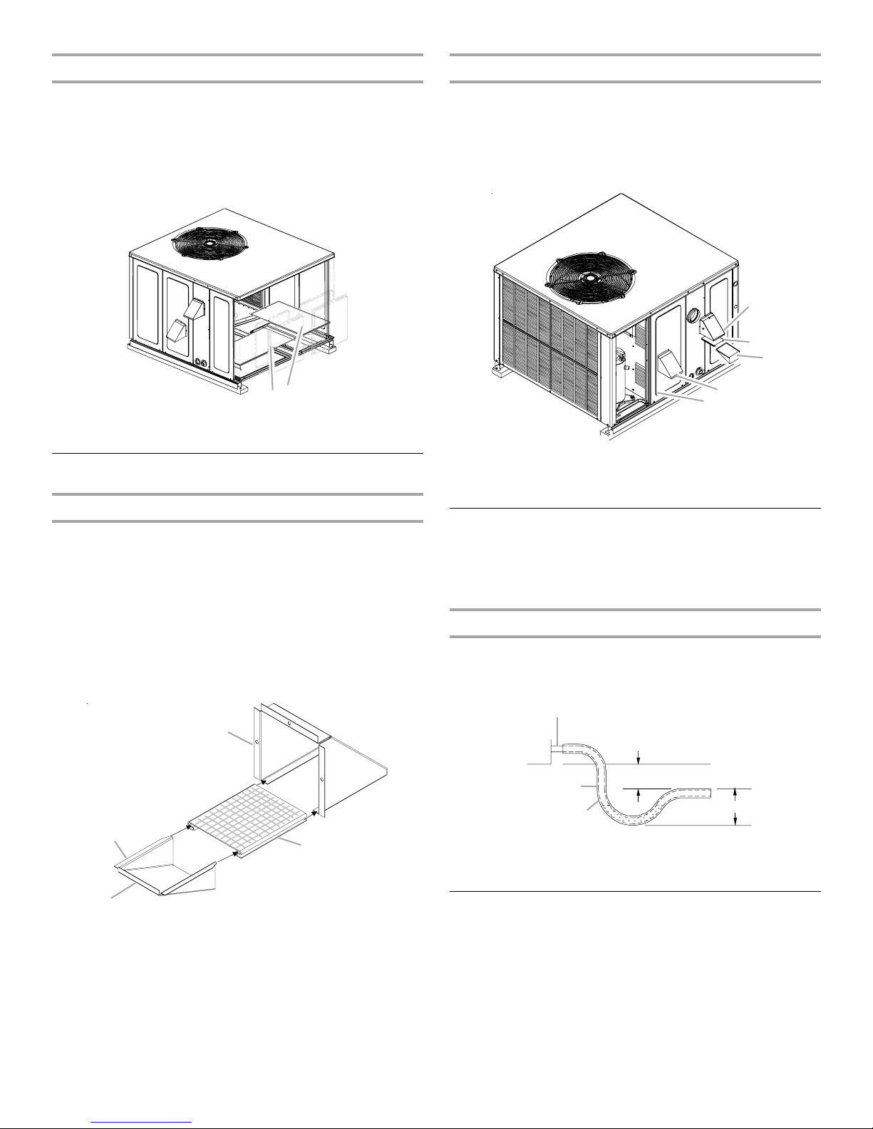
Hood Installation
Install Flue Exhaust Hood
Install the flue exhaust hood, screen and lower flue hood prior to
operation of the unit.
To install the flue hood, screen and lower flue hood:
1. Remove the flue exhaust hood assembly box from the blower
compartment.
2. Slide the screen over the flanges of the lower flue hood.
3. Slide the screen and lower flue hood assembly into the flue
exhaust hood.
Flue Exhaust Hood Assembly
1. Locate the second hood.
2. Using the 3 screws provided, attach the combustion air
intake hood, with the opening facing down, to the heat
exchanger access door.
Hood Attachment
A
B
D
E
A. Flue exhaust hood
B. Screen
C. Lower flue hood
D. Combustion air intake hood
E. Heat exchanger door
Connect Condensate Drain
The condensate drain outlet is a ³⁄₄" threaded PVC fitting located
at the bottom on the side of the unit. A ³⁄₄" drain line with trap
must be installed on all applications to avoid accumulation of
condensate under or around the unit.
Condensate Drain Connection
A ³⁄₄" (1.9 cm) NPT drain connection is supplied for condensate
piping. An external trap must be installed for proper condensate
drainage.
A
D
C
A. Flue exhaust hood
B. Screen
C. Lip
D. Lower flue hood
4. Using the 3 screws provided, attach the flue exhaust hood
assembly, with the opening facing down, over the flue
exhaust opening in the utility panel. See “Hood Attachment”
illustration.
8
A
F
E
D
B
A. Drain connection
B. 2" (5.1 cm) minimum
C. 3" (7.6 cm) minimum
B
C
D. Positive liquid seal (required)
E. Flexible tubing, hose or pipe
F. U n it
Install Ductwork
■ Install ductwork in accordance with NFPA 90B and any local
codes.
■ The use of flexible, noncombustible connectors between the
main trunk ducts and the supply and return air plenums is
recommended to minimize vibration transmission.
■ Plenums must be individually sealed to the unit casing with
ducts terminating inside the structure.
■ Flashing used to cover ductwork must permit removal of
access panels and top. See “Minimum Clearances” in the
“Locations Requirements” section.
Make Electrical Connections
WARNING
HIGH VOLTAGE!
Disconnect ALL power before servicing.
Multiple power sources may be present.
Failure to do so may cause property damage,
personal injury or death.
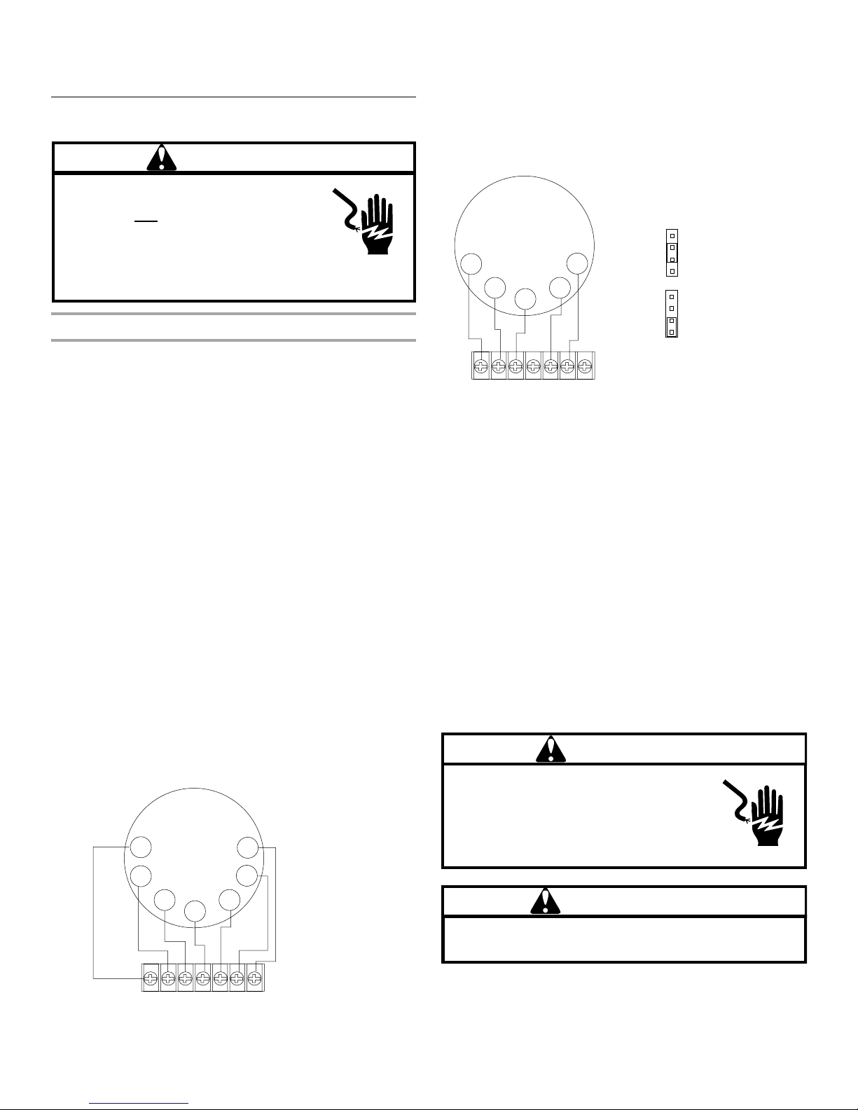
Thermostat
Thermostat Location
Mount the thermostat approximately 5 ft (1.5 m) above the floor,
in an area that has an inside, vibration-free wall and has good air
circulation.
Movement of air must not be obstructed by furniture, door,
draperies, etc. The thermostat must not be mounted where it will
be affected by drafts, hot or cold water pipes or air ducts in walls,
radiant heat from fireplace, lamps, the sun, television, etc.
Consult the Instruction Sheet packaged with the thermostat for
mounting instructions.
NOTE: WGGE4524, WGGE4530, WGGE4537 and WGGE4542
units have 1 stage of mechanical cooling and 2 stages of heating.
All other units have 2 stages of heating and 2 stages of
mechanical cooling. Units which will have economizers may use
thermostats with 2 or 3 stages of cooling. All units can use
single-stage or multistage thermostats. Refer to the following
thermostat illustrations for wiring.
All units have 1 stage of heating and one stage of mechanical
cooling. Units which will have economizers may use thermostats
with 1 or 2 stages of cooling.
The units are designed for operation on 60 hertz current and at
voltages as shown on the rating plate. All internal wiring in the
unit is complete. It is necessary to bring in the power supply to
the contactor as shown on the unit wiring diagram which is
supplied with each unit. Twenty-four volt wiring must be
connected between the unit control panel and the room
thermostat.
2-Stage Heating with 2-Stage Cooling Thermostat
Goodman 6
C
Y2
Y1
Single-Stage Thermostat
To use a single-stage thermostat, move the jumper located to the
left of the terminal strip labeled “Stage Delay” from “NONE” to
“5 MIN” or “10 MIN.” This selection will cause the control to run
on low stage for the selected time (5 or 10 minutes), and then
shift to high stage. This option controls both cooling and heating
modes. If the jumper is not moved, only low-stage cool and
low-stage heat will operate.
NONE
5 MIN
Y
C
RRC
IMPORTANT:
■ Electrical wiring, disconnect means and over-current
protection are to be supplied by the installer. Refer to the
rating plate for the maximum over-current protection,
minimum circuit ampacity and operating voltage. See the
wiring connection diagrams in “Troubleshooting.”
■ Install an adequate sized branch circuit disconnect,
according to the NEC, within sight of and readily accessible
to the unit.
■ The cable or conduit and fittings connected from the
disconnect switch to the unit wiring connections shall be
rated for outdoor use.
■ Check the unit rating plate to determine whether the system
is rated single phase or three phase and follow the
appropriate instructions for connecting the pigtail leads.
■ Plug unused side entry holes with field-supplied plugs to
keep moisture from entering the unit.
■ Low voltage wiring must be separated from line voltage
wiring.
G
W
Y2Y1GW2W1
10 MIN
NONE
5 MIN
10 MIN
5-Minute Delay
Period With Jumper
In This Position
10-Minute Delay
Period With Jumper
In This Position
Line Voltage Connections
WARNING
To avoid the risk of injury, electrical shock
or death, the furnace must be electrically
grounded in accordance with local codes or
in their absence, with the latest edition of the
National Electric Code (NEC).
HIGH VOLTAGE!
Goodman 60
W1
RRC
G
W2
Furnace Integrated
Control Module
Y2Y1GW2W1
WARNING
To avoid the risk of electrical shock, wiring to the unit
must be polarized and grounded.
Goodman 70
9
 Loading...