

Whirlpool WFG525S0JB0, WFG525S0JT0, WFG535S0JZ0, WFG535S0JV0, WFG535S0JS0 Installation Guide
...
INSTALLATION INSTRUCTIONS
30" (76.2 CM) FREESTANDING GAS RANGES
INSTRUCTIONS D’INSTALLATION
CUISINIÈRE À GAZ AUTOPORTANTE DE 30" (76,2 CM)
INSTRUCCIONES DE INSTALACIÓN COCINAS
ELÉCTRICAS INDEPENDIENTES DE 30" (76,2 CM)
Table of Contents/Table des matières/ Tabla de contenidos
RANGE SAFETY ...................................... 2
INSTALLATION REQUIREMENTS ..........4
Tools and Parts ...................................... 4
Location Requirements ......................... 4
Electrical Requirements ....................... 6
Gas Supply Requirements ................... 6
INSTALLATION INSTRUCTIONS ............8
Unpack Range....................................... 8
Install Anti-Tip Bracket .......................... 8
Make Gas Connection .......................... 9
Verify Anti-Tip Bracket Is Installed
andEngaged ....................................... 10
Level Range ......................................... 11
Electronic Ignition System ..................11
Warming Drawer or Premium
StorageDrawer ................................... 13
Storage Drawer ................................... 13
Oven Door ........................................... 14
Complete Installation .......................... 14
GAS CONVERSIONS ............................. 15
Propane Gas Conversion .................... 15
Natural Gas Conversion ...................... 18
SÉCURITÉ DE LA CUISINIÈRE ............ 21
EXIGENCES D’INSTALLATION ............22
Outils et pièces .................................... 22
Exigences d’emplacement .................. 23
Spécications électriques ................... 24
Spécications de l’alimentation
en gaz .................................................. 25
INSTRUCTIONS D’INSTALLATION ...... 26
Déballage de la cuisinière ................... 26
Installation de la bride
antibasculement .................................. 27
Raccordement à la canalisation
de gaz .................................................. 28
Vérier que la bride antibasculement
estbien installée et engagée .............. 29
Réglage de l’aplomb de la cuisinière .. 30
Système d’allumage électronique.......30
Tiroir-réchaud ou tiroir de remisage
dequalité supérieure ...........................32
Tiroir de remisage ................................33
Porte du four ....................................... 33
Achever l’installation ........................... 34
CONVERSIONS POUR
CHANGEMENT DE GAZ ....................... 35
Conversion pour l’alimentation
aupropane .......................................... 35
Conversion pour l’alimentation
augaznaturel ...................................... 39
SEGURIDAD DE LA COCINA ............... 42
REQUISITOS DE INSTALACIÓN .......... 44
Herramientas y piezas ......................... 44
Requisitos de ubicación ...................... 44
Requisitos eléctricos .......................... 46
Requisitos de suministro de gas ........46
INSTRUCCIONES DE INSTALACIÓN .. 48
Desembale la cocina ........................... 48
Instalación del soporte antivuelco ...... 48
Conexión del suministro de gas .........49
Verique que el soporte anti-vuelco
estéinstalado y enganchado .............. 50
Nivelación de la cocina ....................... 51
Sistema de encendido electrónico ..... 52
Cajón de calentamiento o cajón
dealmacenamiento premium
(enalgunos modelos) .......................... 54
Cajón de almacenamiento
(enalgunos modelos) .......................... 54
Puerta del horno .................................. 54
Completar la instalación ..................... 55
CONVERSIONES DE GAS .................... 56
Conversión a gas propano ..................56
Conversión a gas natural .................... 60
IMPORTANT:
Save for local electrical inspector’s use.
Installer: Leave installation instructions with the homeowner.
Homeowner: Keep installation instructions for future reference.
IMPORTANT:
Conserver ces instructions à l’usage de l’inspecteur des installations électriques local
Installateur: Remettre les instructions d’installation au propriétaire.
Propriétaire: Conserver les instructions d’installation pour référence ultérieure.
IMPORTANTE:
Guarde para tener a disposición del inspector de electricidad local.
Instalador: Déjele las instrucciones de instalación al propietario.
Propietario: Guarde las instrucciones de instalación para futuras consultas.
W11333091B

RANGE SAFETY
Your safety and the safety of others are very important.
We have provided many important safety messages in this manual and on your appliance. Always read and obey all safety
messages.
This is the safety alert symbol.
This symbol alerts you to potential hazards that can kill or hurt you and others.
All safety messages will follow the safety alert symbol and either the word “DANGER” or “WARNING.”
These words mean:
You can be killed or seriously injured if you don't immediately
DANGER
WARNING
All safety messages will tell you what the potential hazard is, tell you how to reduce the chance of injury, and tell you what can
happen if the instructions are not followed.
WARNING: If the information in these instructions is not followed exactly, a fire or
explosion may result causing property damage, personal injury or death.
follow instructions.
You
can be killed or seriously injured if you don't
instructions.
follow
– Do not store or use gasoline or other flammable vapors and liquids in the vicinity of this
or any other appliance.
– WHAT TO DO IF YOU SMELL GAS:
Do not try to light any appliance.
•
Do not touch any electrical switch.
•
Do not use any phone in your building.
•
Immediately call your gas supplier from a neighbor's phone. Follow the gas supplier's
•
instructions.
If you cannot reach your gas supplier, call the fire department.
•
– Installation and service must be performed by a qualified installer, service agency or
the gas supplier.
WARNING: Gas leaks cannot always be detected by smell.
Gas suppliers recommend that you use a gas detector approved by UL or CSA.
For more information, contact your gas supplier.
If a gas leak is detected, follow the “What to do if you smell gas” instructions.
2
IMPORTANT: Do not install a ventilation system that blows air downward toward this gas cooking appliance. This type of
ventilation system may cause ignition and combustion problems with this gas cooking appliance resulting in personal injury or
unintended operation.
In the State of Massachusetts, the following installation instructions apply:
Installations and repairs must be performed by a qualified or licensed contractor, plumber, or gasfitter qualified or licensed by
the State of Massachusetts.
Acceptable Shut-off Devices: Gas Cocks and Ball Valves installed for use shall be listed.
A flexible gas connector, when used,must not exceed 4 feet (121.9 cm).
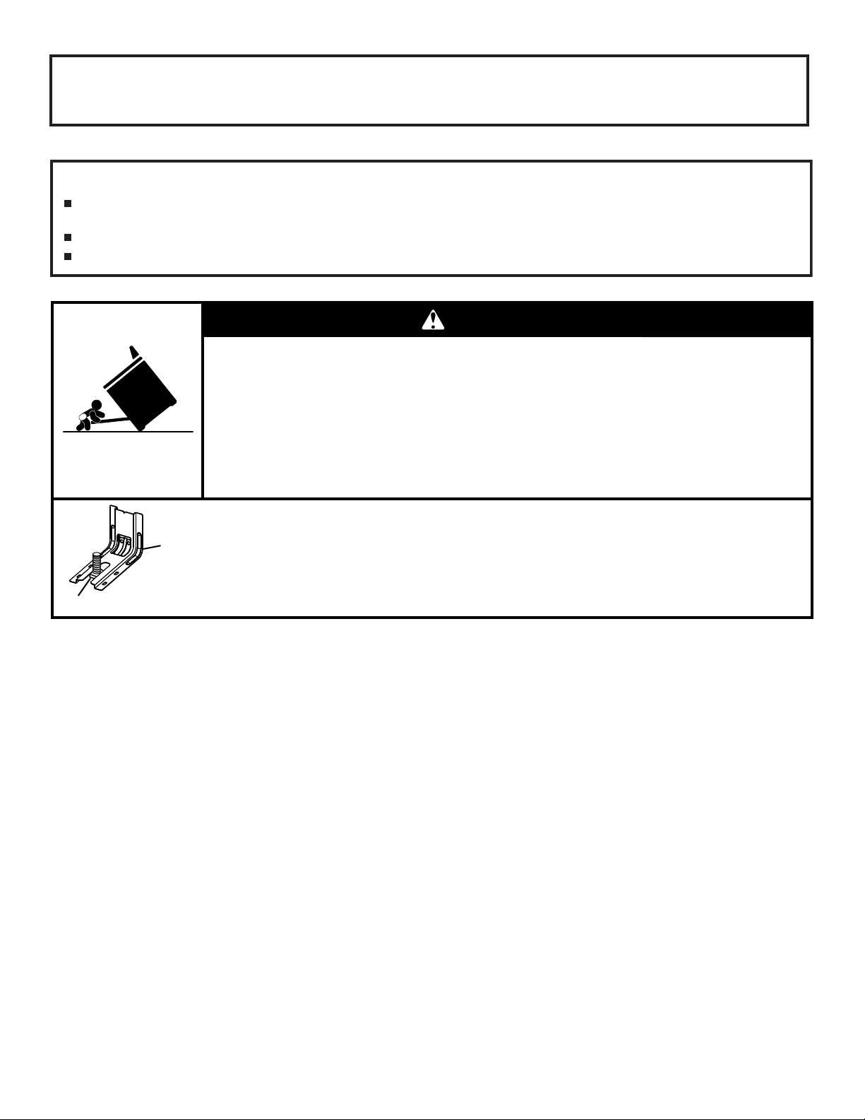
WARNING
Tip Over Hazard
A child or adult can tip the range and be killed.
Install anti-tip bracket to floor or wall per installation instructions.
Slide range back so rear range foot is engaged in the slot of the anti-tip bracket.
Re-engage anti-tip bracket if range is moved.
Do not operate range without anti-tip bracket installed and engaged.
Failure to follow these instructions can result in death or serious burns to children and adults.
Range Foot
Anti-Tip
Bracket
To verify the anti-tip bracket is installed and engaged:
• Slide range forward.
• Look for the anti-tip bracket securely attached to floor or wall.
• Slide range back so rear range foot is under anti-tip bracket.
• See installation instructions for details.
3
INSTALLATION REQUIREMENTS
Tools and Parts
Gather the required tools and parts before starting installation.
Read and follow the instructions provided with any tools listed
here.
Tools Needed
■ Tape measure
■ Flat-blade screwdriver
■ Phillips screwdriver
■ Level
■ Hand or electric drill
■ Wrench or pliers
■ Pipe wrench
■ 15/16" combination
wrench
■ 1/4" drive ratchet
■ 3/8" nut driver
■ 1/8" drill bit (for wood
oors)
■ Marker or pencil
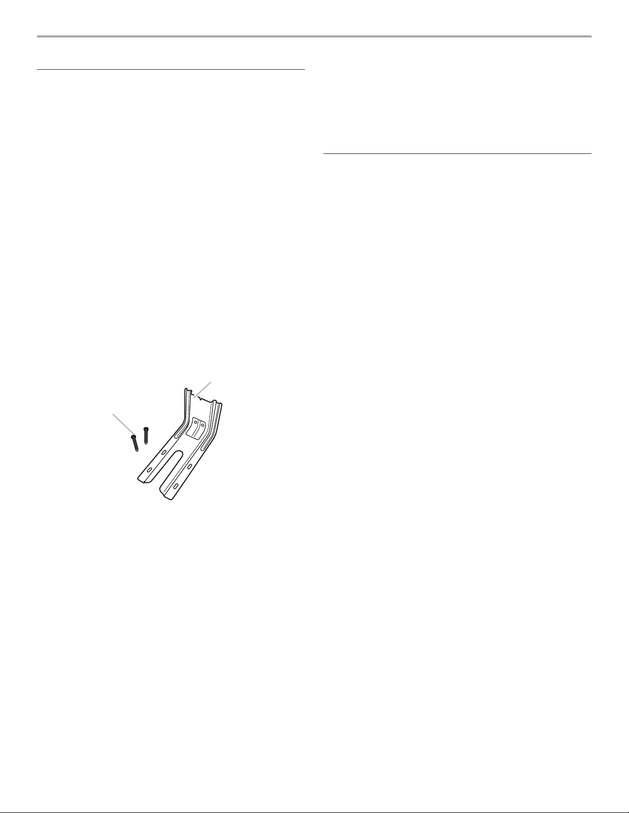
Parts Supplied
Check that all parts are included.
B
A. Anti-tip bracket
B. #12 x 15⁄8" (4.1 cm) screws (2)
■ Pipe-joint compound
resistant to Propane gas
■ Noncorrosive leak-
detection solution
For Propane/Natural Gas
Conversions
■ 3/8" combination wrench
■ 1/2" combination wrench
■ 5/8" combination wrench
■ 9/32" nut driver
■ Quadrex
®†
or Phillips
screwdriver
■ Masking tape
A
■ Anti-tip bracket must be securely mounted to oor or wall.
The thickness of ooring may require longer screws to
anchor bracket to the oor.
Parts needed
Check local codes and consult gas supplier. Check existing gas
supply and electrical supply. See “Electrical Requirements” and
“Gas Supply Requirements” sections.
Location Requirements
IMPORTANT: Observe all governing codes and ordinances. Do
not obstruct ow of combustion and ventilation air.
■ It is the installer’s responsibility to comply with installation
clearances specied on the model/serial rating plate. The
model/serial rating plate is located on the oven frame behind
the top left side of the oven door.
■ Recessed installations must provide complete enclosure of
the sides and rear of the range.
■ All openings in the wall or oor where range is to be installed
must be sealed.
■ Do not seal the range to the side cabinets.
■ Cabinet opening dimensions that are shown must be used.
Given dimensions are minimum clearances.
■ The anti-tip bracket must be installed. To install the anti-tip
bracket shipped with the range, see “Install Anti-Tip Bracket”
section.
■ Grounded electrical supply is required. See “Electrical
Requirements” section.
■ Proper gas supply connection must be available. See “Gas
Supply Requirements” section.
■ Contact a qualied oor covering installer to check that the
oor covering can withstand at least 200°F (93°C).
■ Use an insulated pad or 1/4" (6.4 mm) plywood under range
if installing range over carpeting.
IMPORTANT: To avoid damage to your cabinets, check with
your builder or cabinet supplier to make sure that the materials
used will not discolor, delaminate or sustain other damage. This
oven has been designed in accordance with the requirements
of UL and CSA International and complies with the maximum
allowable wood cabinet temperatures of 194°F (90°C).
†® QUADREX is a registered trademark of NLW Holdings, Inc.
4
Mobile Home - Additional Installation Requirements
The installation of this range must conform to the Manufactured
Home Construction and Safety Standard, Title 24 CFR,
Part 3280 (formerly the Federal Standard for Mobile Home
Construction and Safety, Title 24, HUD Part 280). When such
standard is not applicable, use the Standard for Manufactured
Home Installations, ANSI A225.1/NFPA 501A or with local codes.
Mobile home installations require:
■ When this range is installed in a mobile home, it must be
secured according to the instructions in this document.
Cabinet Dimensions
Cabinet opening dimensions shown are for 25" (64.0 cm)
countertop depth, 24" (61.0 cm) base cabinet depth and
36"(91.4 cm) countertop height.
IMPORTANT: If installing a range hood or microwave hood
combination above the cooking surface, follow the range hood
or microwave hood combination installation instructions for
dimensional clearances above the cooktop surface.
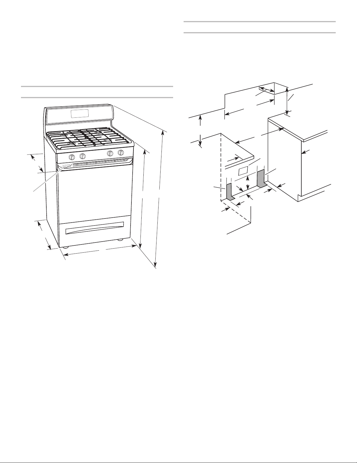
Product Dimensions
A
F
E
D
A. 277⁄8" (70.8 cm) max. depth with handle
B. 36" (91.4 cm) cooktop height (max.) with leveling legs screwed all the
way in*
C. 467⁄8" (119.1 cm) overall height (max.) with leveling legs screwed all
the way in*
D. 297⁄8" (75.9 cm) width
7⁄
16
E. 25
" (64.6 cm) depth. Back of range to front of cooktop**
F. Model/serial rating plate (located on the oven frame behind the top left
side of the oven door)
C
B
B
D
C
A
E
N
M
L
H
F
G
F
I
K
J
K
A. 18" (45.7 cm) upper side cabinet to countertop
B. 13" (33 cm) max. upper cabinet depth
C. 30" (76.2 cm) min. opening width
D. 30" (76.2 cm) min. clearance to top of cooktop
E. 30¹⁄8" (76.5 cm) min. opening width
F. The shaded areas are recommended for installation of rigid
gas pipe.
G. 4¹⁄2" (11.4 cm)
H. 8" (20.3 cm)
I. 17" (43.2 cm)
J. 2" (5.1 cm)
K. 4¹⁄2" (11.4 cm)
L. 2" (5.1 cm) min. clearance from both sides of range to side
wall or other combustible material.
M. Grounded outlet
N. Cabinet door or hinges should not extend into the cutout.
IMPORTANT: Range must be level after installation. Follow the
instructions in the “Level Range” section. Using the cooktop as a
reference for leveling the range is not recommended.
*Range can be raised approximately 1" (2.5 cm) by adjusting the
leveling legs.
**Front of door and drawer may extend further forward,
depending on styling.
5
Electrical Requirements
Gas Supply Requirements
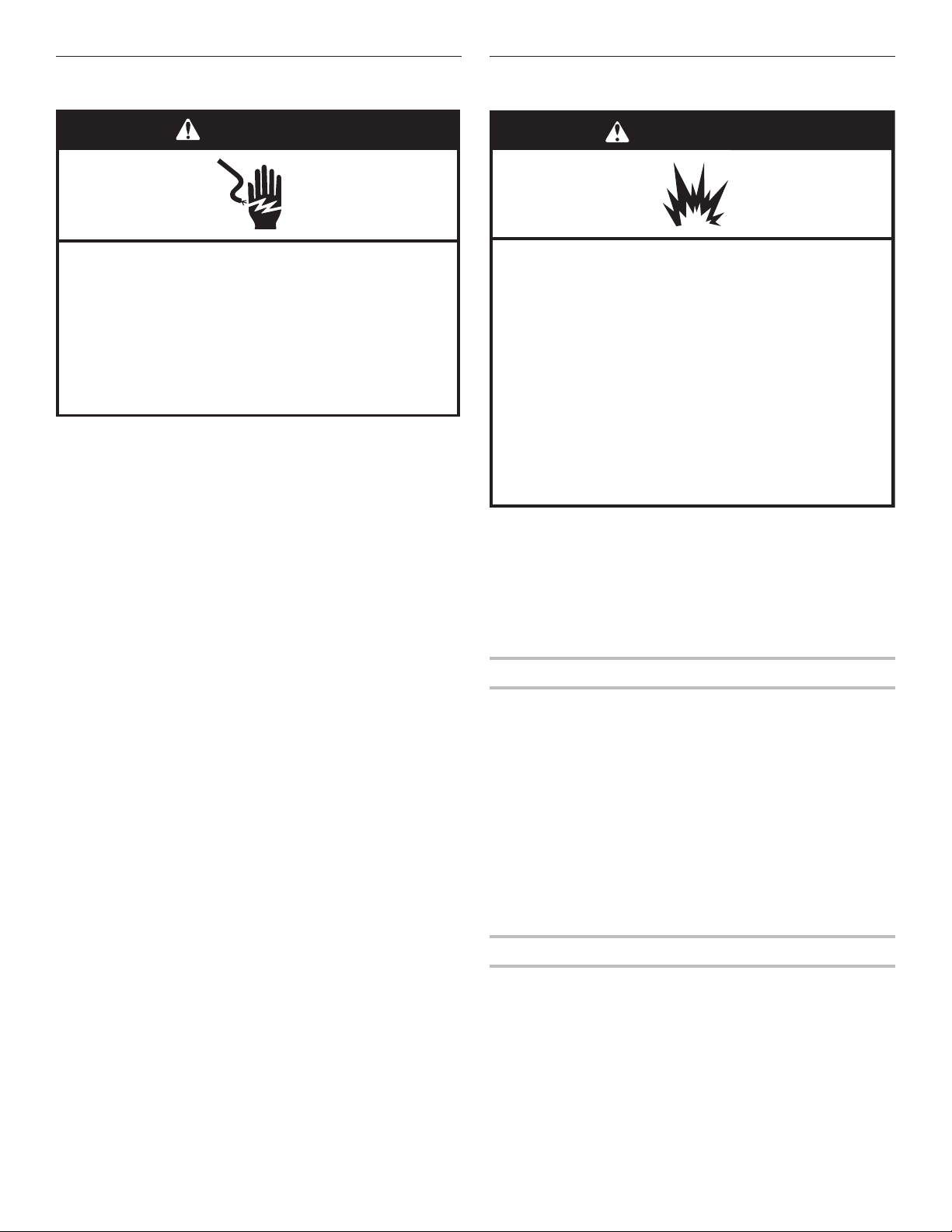
WARNING
Electrical Shock Hazard
Plug into a grounded 3 prong outlet.
Do not remove ground prong.
Do not use an adapter.
Do not use an extension cord.
Failure to follow these instructions can result in death,
fire, or electrical shock.
IMPORTANT: The range must be electrically grounded in
accordance with local codes and ordinances, or in the absence
of local codes, with the National Electrical Code, ANSI/NFPA 70
or Canadian Electrical Code, CSA C22.1.
This range is equipped with an electronic ignition system that
will not operate if plugged into an outlet that is not properly
polarized. If code permit and a separate ground wire is used, it is
recommended that a qualied electrical installer determine that
the ground path is adequate.
A copy of the above code standards can be obtained from:
National Fire Protection Association
1 Batterymarch Park
Quincy, MA 02169-7471
CSA International
8501 East Pleasant Valley Road
Cleveland, OH 44131-5575
■ A 120 V, 60 Hz, AC only, 15 A fused, electrical circuit
is required. A time-delay fuse or circuit breaker is also
recommended. It is recommended that a separate circuit
serving only this range be provided.
■ Electronic ignition systems operate within wide voltage limits,
but proper grounding and polarity are necessary. Check that
the outlet provides 120 V power and is correctly grounded.
■ This gas range is not required to be plugged into a GFCI
(Ground-Fault Circuit Interrupter) outlet. It is recommended
that you not plug an electric spark ignition gas range or any
other major appliance into a GFCI wall outlet as it may cause
the GFCI to trip during normal cycling.
■ Performance of this range will not be affected if operated
on a GFCI-protected circuit. However, occasional nuisance
tripping of the GFCI breaker is possible due to the normal
operating nature of electronic gas ranges.
■ The wiring diagram is located on the back of the range in a
clear plastic bag.
NOTE: The metal chassis of the range must be grounded in
order for the control panel to work. If the metal chassis of the
range is not grounded, no keypads will operate. Check with a
qualied electrician if you are in doubt as to whether the metal
chassis of the range is grounded.
WARNING
Explosion Hazard
Use a new CSA International approved gas supply line.
Install a shut-off valve.
Securely tighten all gas connections.
If connected to propane, have a qualified person make
sure gas pressure does not exceed 14" (36 cm) water
column.
Examples of a qualified person include:
licensed heating personnel,
authorized gas company personnel, and
authorized service personnel.
Failure to do so can result in death, explosion, or fire.
Observe all governing codes and ordinances.
IMPORTANT: This installation must conform with all local codes
and ordinances. In the absence of local codes, installation must
conform with American National Standard, National Fuel Gas
Code ANSI Z223.1 - latest edition or CAN/CGA B149 - latest
edition.
IMPORTANT: Leak testing of the range must be conducted
according to the manufacturer’s instructions.
Type of Gas
Natural Gas:
■ This range is factory set for use with Natural gas. See “Gas
Conversions” section. The model/serial rating plate located
on the oven frame behind the top left side of the oven door
has information on the types of gas that can be used. If the
types of gas listed do not include the type of gas available,
check with the local gas supplier.
Propane Gas Conversion:
Conversion must be done by a qualied service technician.
No attempt shall be made to convert the appliance from the gas
specied on the model/serial rating plate for use with a different
gas without consulting the serving gas supplier. See “Gas
Conversions” section.
Gas Supply Line
■ Provide a gas supply line of 3/4" (1.9 cm) rigid pipe to the
range location. A smaller size pipe on longer runs may
result in insufcient gas supply. With Propane gas, piping or
tubing size can be 1/2" (1.3 cm) minimum. Usually, Propane
gas suppliers determine the size and materials used in the
system.
NOTE: Pipe-joint compounds that resist the action of
Propane gas must be used. Do not use TEFLON®† tape.
†®TEFLON is a registered trademark of Chemours.
6
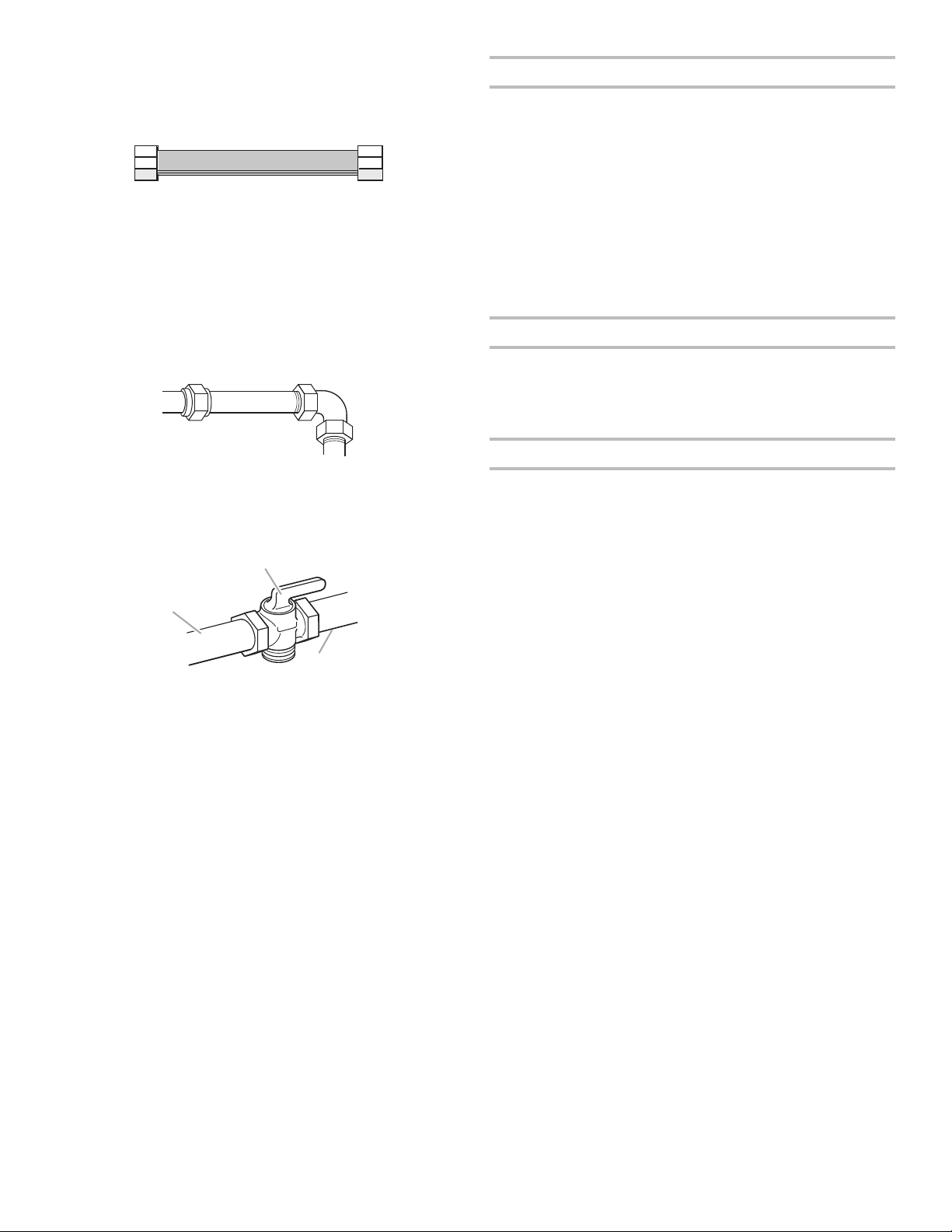
Flexible metal appliance connector:
A
C
■ If local codes permit, a new CSA design-certied, 4 to
5ft (122 to 152.4 cm) long, 1/2" (1.3 cm) or 3/4" (1.9 cm)
I.D. (inside diameter), exible metal appliance connector
may be used for connecting range to the gas supply line.
■ A 1/2" (1.3 cm) male pipe thread is needed for
connection to the female pipe threads of the inlet to the
appliance pressure regulator.
■ Do not kink or damage the exible metal tubing when
moving the range.
Rigid pipe connection:
The rigid pipe connection requires a combination of pipe ttings
to obtain an in-line connection to the range. The rigid pipe must
be level with the range connection. All strains must be removed
from the supply and fuel lines so range will be level and in line.
Gas Pressure Regulator
The gas pressure regulator supplied with this range must be
used. The inlet pressure to the regulator should be as follows for
proper operation:
Natural Gas:
Minimum pressure: 5" (12.7 cm) WCP
Maximum pressure: 14" (35.5 cm) WCP
Propane Gas:
Minimum pressure: 11" (27.9 cm) WCP
Maximum pressure: 14" (35.5 cm) WCP
Contact local gas supplier if you are not sure about the inlet
pressure.
Burner Input Requirements
Input ratings shown on the model/serial rating plate are for
elevations up to 2,000 ft (609.6 m).
For elevations above 2,000 ft (609.6 m), ratings are reduced at
a rate of 4% for each 1,000 ft (304.8 m) above sea level (not
applicable for Canada).
Gas Supply Pressure Testing
■ Must include a shutoff valve:
Install a manual gas line shut-off valve in an easily accessible
location. Do not block access to shut-off valve. The valve is
for turning on or shutting off gas to the range.
B
A. Gas supply line
B. Shutoff valve “open” position
C. To range
Gas supply pressure for testing regulator must be at least
1" (2.5 cm) water column pressure above the manifold pressure
shown on the model/serial rating plate.
Line pressure testing above 1/2 psi (3.5 kPa) gauge
14"(35.5cm) WCP
The range and its individual shutoff valve must be disconnected
from the gas supply piping system during any pressure testing of
that system at test pressures in excess of 1/2 psi (3.5 kPa).
Line pressure testing at 1/2 psi (3.5 kPa) gauge 14" (35.5 cm)
WCP or lower
The range must be isolated from the gas supply piping system
by closing its individual manual shutoff valve during any pressure
testing of the gas supply piping system at test pressures equal
to or less than 1/2 psi (3.5 kPa).
7
 Loading...