

Whirlpool WED7600XW0 Parts Diagram
TECH SHEET - DO NOT DISCARD PAGE 1
3. If this test mode has been entered successfully, all indicators on the console
WARNING
Electrical Shock Hazard
Disconnect power before servicing.
Replace all parts and panels before operating.
Failure to do so can result in death or
electrical shock.
IMPORTANT
Electrostatic Discharge (ESD) Sensitive Electronics
ESD problems are present everywhere. ESD may damage or weaken the
machine control electronics. The new control assembly may appear to
work well after repair is finished, but failure may occur at a later date
due to ESD stress.
Use an anti-static wrist strap. Connect wrist strap to green ground
■
connection point or unpainted metal in the appliance
Touch your finger repeatedly to a green ground connection point or
unpainted metal in the appliance.
Before removing the part from its package, touch the anti-static bag
■
to a green ground connection point or unpainted metal in the
appliance.
Avoid touching electronic parts or terminal contacts; handle machine
■
control electronics by edges only.
When repackaging failed machine control electronics in anti-static
■
bag, observe above instructions.
-OR-
are illuminated for 5 seconds with showing in the Estimated Time
Remaining two-digit display.
88
DIAGNOSTIC: Unsuccessful Entry
If entry into diagnostic mode is unsuccessful, press the Power button twice.
If indicators come on, try to use a different button than was used to activate
➔
the diagnostic test mode. If that button fails to enter the diagnostic mode,
something is faulty, and it is not possible to enter the diagnostic mode. Go to
TEST #2, page 4.
➔ If no indicators come on after pressing the Power button, go to TEST #1,
page 4.
DIAGNOSTIC: Saved Fault Codes
If there are saved fault codes, the most recent fault code will alternately show “F-”
and “XX” where XX is the fault code.
Press and release
the same button
used to activate
Diagnostics
Repeat
Repeat
Repeat
➔
beep tone➔Second most recent fault code is displayed.
➔
beep tone➔Third most recent fault code is displayed.
➔
beep tone➔Fourth most recent fault code is displayed.
➔
All indicators momentarily turn off, then stay on.
DIAGNOSTIC: Console Buttons and Indicators
Pressing the console buttons or rotating the cycle selector will sound a beep and
will turn on or off the corresponding indicators as shown in Figure 1, Console
Diagnostics, page 2. Pressing Time Adjust
turn the left digit of the display on or off. Pressing Time Adjust
sound a beep and turn the right digit of the display on or off.
➔ If indicators fail to turn on or off and beep after pressing buttons or rotating
the cycle selector, go to TEST #6, page 8.
▲ (more time) will sound a beep and
▼ (less time) will
DIAGNOSTIC GUIDE
Before servicing, check the following:
■
Make sure there is power at the wall outlet.
■
Has a household fuse blown or circuit breaker tripped? Wasaregular fuse
used? Useatime-delay fuse.
■
Is dryer vent properly installed and clear of lint or obstructions?
■
All tests/checks should be made with a VOM (volt-ohm-milliammeter) or DVM
(digital-voltmeter) having a sensitivity of 20,000 Ω per volt DC or greater.
■
Check all connections before replacing components. Look for broken or loose
wires, failed terminals, or wires not pressed into connectors far enough.
■
A potential cause of a control not functioning is corrosion on connections.
Observe connections and check for continuity with an ohmmeter.
■
Connectors: Look at top of connector. Check for broken or loose wires. Check
for wires not pressed into connector far enough to engage metal barbs.
■
Resistance checks must be made with dryer unplugged or power disconnected.
DIAGNOSTIC TESTS
These tests allow factory or service personnel to test and verify all inputs to the
machine control electronics. You may want to do a quick and overall checkup of
the dryer with these tests before going to specific troubleshooting tests.
ACTIVATING THE DIAGNOSTIC TEST MODE
1. Be sure the dryer is in standby mode (plugged in with all indicators off, or with
only the Done indicator on).
2. Select any one button (except Power) and follow the steps below, using the
same button (remember the button):
Press/hold
2-5 seconds
Release for
➔
2-5 seconds
Press/hold
➔
2-5 seconds
Release for
➔
2-5 seconds
Press/hold
➔
2-5 seconds
DIAGNOSTIC: Door Switch
Opening the door should cause a beep and an alphanumeric number to be
displayed. Closing the door should cause a beep and to be displayed.
➔ If opening the door fails to cause a beep and a number and letter to be
displayed, go to TEST #7, page 8.
88
DIAGNOSTIC: Moisture Sensor
1. Open the door and locate two metal strips on the face of the lint screen
housing. Using a wet cloth or one finger, jointly touch both strips.
➔ If a continuous beep tone is heard and an alphanumeric number is
displayed on the console, the sensor is OK.
➔ If a continuous beep tone is not heard, or if a continuous beep tone is heard
before touching both moisture strips, go to step 2.
2. Check to see if there is water in the dryer around the moisture strips.
➔ If no water is present, go to TEST#5, page 7.
➔ If water is present, wipe the strips off with a dry cloth and repeat step 1.
➔ If wiping the strips does not stop the beeping, run a timed dry cycle for 2
minutes to dry out the drum, then repeat this diagnostic test.
DIAGNOSTIC: Motor, Heater, and Console ID
Close the door. Press the Start button. The motor and heater will turn on, and the
display will show one of the following console IDs:
➔
If none of the Console IDs listed above are displayed, replace the user
interface assembly. See Accessing & Removing the Electronic Assemblies,
page 9.
➔
If the motor does not turn on, go to TEST #3, page 4.
➔
If no heat is detected, go to TEST #4, page 6.
c9, ca, cb, cc.
W10301482B .ON TRAPYLNO ESU S’NAICINHCET ECIVRES ROF
TECH SHEET - DO NOT DISCARD PAGE 2
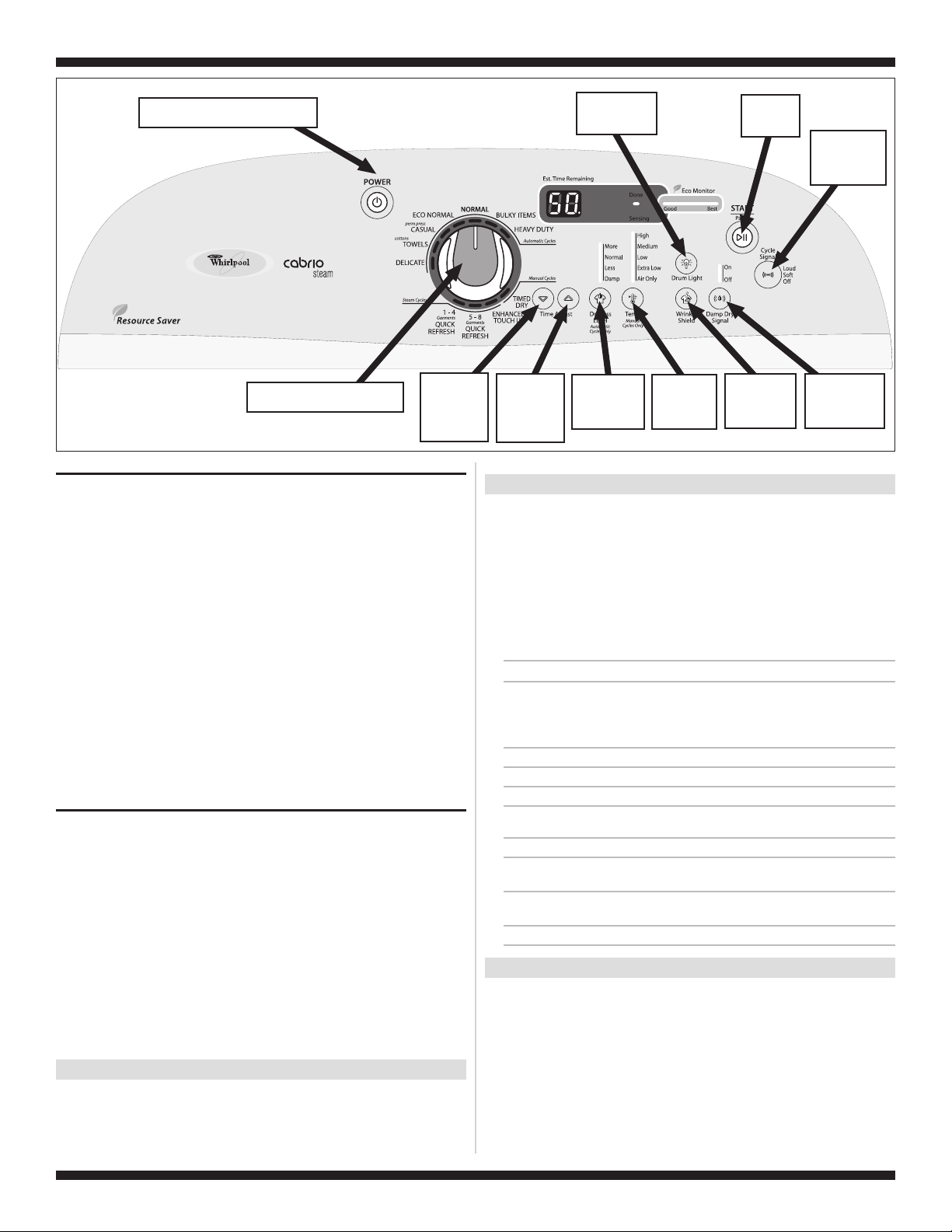
Power button controls “Sensing”
and “Done” indicators.
“Less Time”
button turns
the right digit
of the display
on or off.
Figure 1.
Rotating the knob turns indicators
on or off.
Console Diagnostics.
DIAGNOSTIC: Displaying Inlet Air Flow
Used to display the air flow value at the inlet of the heater box being measured by
the machine control.
After all saved fault codes have been displayed, press the Wrinkle Shield button
to activate air flow detection. A 30 or 50 second countdown timer will start and the
dryer will turn on.
➔ If the dryer is cold, the countdown will star t at 50 seconds.
NOTE: If the dryer is extremely cold (less than 40°F [4.4°C]), the air flow may
not be detected properly, and “--” will be displayed.
➔ If the dryer is hot, the countdown timer will start at 30 seconds (cool down
period) followed by an additional 50 second countdown.
A Dryness Level modifier LED will also be illuminated to indicate the air flow
range corresponding to the number displayed.
■
The More LED will be illuminated for air flow readings above 40 cfm.
■
The Normal LED will be illuminated for air flow readings between 29 and40 cfm.
■
The Less LED will be illuminated for air flow readings less than 29 cfm.
➔ If air flow value is low, check to make sure the lint screen is clean, the door
seal is in place, and the vent is not obstructed.
“More Time”
button turns
the left digit
of the display
on or off.
Drum Light
button controls
its own indicator.
Dryness Level
button controls
all indicators
above button.
Temp button
controls all
indicators
above button.
Start button
turns on the
dryer.
Wrinkle Shield
button controls
its own
indicator.
Cycle Signal
button controls
the Eco Monitor
LEDs.
Damp Dry Signal
button controls
all indicators
above button.
ACTIVATING THE MANUAL LOAD TEST
1. Be sure the dryer is in standby mode (plugged in with all indicators off, or with
only the Done indicator on).
2. Select any one button (except Power) and follow the steps below, using the
same button (remember the button):
Press/
hold 2-5
seconds
88
flashes (this step starts the Manual Load sequence):
Now press any key (except Power) and the control will advance through each step
of the following sequence:
Non Steam Model
➔
seconds
Release
for 2-5
➔
hold 2-5
seconds
Press/
➔
Release
for 2-5
seconds
➔
hold 2-5
seconds
Press/
➔
seconds
Release
for 2-5
➔
hold 2-5
seconds
Press/
flashes momentarily, the motor starts right away, and the Heavy Duty LED
➔
1. Turn on motor.
2. Motor + heater.
3. No loads on (motor + heater).
4. Repeat using same button.
Flash “Heavy Duty” LED.
➔
Flash “Casual” LED.
➔
Flash “Normal” LED.
➔
Start sequence again at 1.
DIAGNOSTIC: Displaying Line Voltage
Used to display the line voltage currently being measured by the machine control:
After all saved fault codes have been displayed, press the Cycle Signal
button. The last 2 digits of the voltage value will be displayed on the dual
7-segment display.
A Dryness Level modifier LED will also be illuminated to indicate the voltage range
corresponding to the number displayed. The Dryness Level LEDs relate to specific
voltage ranges as follows:
■
The More LED will be illuminated for high voltage readings (above 260 VAC).
■
The Normal LED will be illuminated for normal voltage readings (200-260 VAC).
■
The Less LED will be illuminated for low voltage readings (below 200 VAC).
➔ If the line voltage is not seen on L2, the display will flash .
2
L
Go to TEST #1, page 4.
DEACTIVATING THE DIAGNOSTIC TEST MODE
Press the Power button twice to exit diagnostics.
Steam Model
2. Motor + heater + water valve.
Motor + heater + water valve +
3.
drum light.
No loads on (motor + heater +
4.
water valve).
5. Repeat using same button.
➔
Flash “Delicate” LED.
➔
Flash “Drum Light” LED.
➔
Flash “Normal” LED.
➔
Start sequence again at 1.
DEACTIVATING THE MANUAL LOAD TEST
Press the Power button to exit this mode.
W10301482B .ON TRAPYLNO ESU S’NAICINHCET ECIVRES ROF
TECH SHEET - DO NOT DISCARD PAGE 3
DISPLAY FAULT CODES
The fault codes below would be indicated when attempting to start a drying cycle
or after activating the diagnostic test mode.
DISPLAY DESCRIPTION EXPLANATION / RECOMMENDED PROCEDURE
PF
2
L
AF
:01
F
:02
F
:22
F
:23
F
:24
F
:25
F
:26
F
:28
F
:29
F
:30
F
:50
F
Power
Failure
Low/No Line
Voltage
Restricted
Air Flow
Condition
Primary
Control
Failure
Keypad/
User Interface
Failure
Exhaust
Thermistor
Open
Exhaust
Thermistor
Shorted
Inlet
Thermistor
Open
Inlet
Thermistor
Shorted
Motor Drive
System Failure
Moisture
Sensor Open
Moisture
Sensor
Shorted
Restricted
Air Flow
Condition
Water Valve
Failure
PF flashes to indicate that a power failure
occurred while the dryer was running. Press Start
to continue the cycle, or press Power to clear the
display.
L2 flashes if low line voltage (less than 50V) is
detected at installation.
Check to see if a household fuse has blown or
■
a circuit breaker has tripped.
Confirm the power cord is properly installed
■
and plugged into the power outlet.
Check the relay connections on the machine
■
control electronics. See TEST #4, page 6.
AF flashes if a restricted air flow condition exists.
Check to make sure the lint screen is clean, the
door seal is in place, and the vent is not
obstructed.
F:01 flashes when there is a primary control
failure. Replace the machine control electronics.
See Accessing & Removing the Electronic
Assemblies, page 9.
F:02 flashes when there is a stuck button or user
interface mismatch. This fault code will ONLY
appear when in the diagnostic test mode. See
TEST #6, page 8.
F:22 flashes if the exhaust thermistor is open.
See TEST #4a, page 6.
F:23 flashes if the exhaust thermistor has
shorted. See TEST #4a, page 6.
F:24 flashes if the inlet thermistor is open.
This fault code will ONLY appear when in the
diagnostic test mode. See TEST #4a, page 6.
F:25 flashes if the inlet thermistor is shorted.
This fault code will ONLY appear when in the
diagnostic test mode. See TEST #4a, page 6.
F:26 flashes if there is a motor drive system
failure. See TEST #3, page 4.
F:28 flashes if the moisture sensor strip is open.
This fault code will ONLY appear when in the
diagnostic test mode. See TEST #5, page 7.
F:29 flashes if the moisture sensor strip has
shorted. This fault code will ONLY appear when in
the diagnostic test mode. See TEST #5, page 7.
F:30 flashes if a restricted air flow condition
exists. This fault code will ONLY appear when in
the diagnostic test mode. Check to make sure the
lint screen is clean, the door seal is in place, and
the vent is not obstructed.
F:50 flashes if no voltage is detected at the water
valve relay. Check that the wires are plugged in on
the valve and at the relay on the machine control
electronics. See TEST #8, page 8. This fault code
appears ONLY when in the diagnostic test mode.
TROUBLESHOOTING GUIDE
Some tests will require accessing components. See figure 2, page 4 for component
locations.
PROBLEM POSSIBLE CAUSE / TEST
NOTE: Possible Cause/Tests MUST be performed
in the sequence shown for each problem.
WON’T POWER UP.
(No response when
buttons are pressed.)
WON’T START CYCLE
WHEN START BUTTON
IS PRESSED.
WON’T SHUT OFF
WHEN EXPECTED.
CONTROL WON’T
ACCEPT SELECTIONS.
WON’T HEAT.
HEATS IN AIR CYCLE.
SHUTS OFF BEFORE
CLOTHES ARE DRY.
1. Supply connections. See TEST #1, page 4.
2. Unplug dryer or disconnect power. Check harness
connections.
3. User interface assembly. See TEST #6, page 8.
1. If number display flashes, check to be sure the
door is completely shut, and press and hold down
Start for about 1 second.
2. See TEST #3, page 4.
3. See TEST #7, page 8.
1. Check Power button. See TEST #6, page 8.
2. User interface assembly. See TEST #6, page 8.
3. Moisture sensor. See TEST #5, page 7.
User interface assembly. See TEST #6, page 8.
1. Heater. See TEST #4, page 6.
2. Unplug dryer or disconnect power. Check harness
connections.
3. Check installation.
Heater. See TEST #4, page 6.
1. Check the dryness setting for auto cycles.
2. Check for full lint screen.
3. Check for clogged vent.
4. Moisture sensor. See TEST #5, page 7.
5. Dryness adjust. See Adjusting Customer-Focused
Drying Modes, page 8.
W10301482B .ON TRAPYLNO ESU S’NAICINHCET ECIVRES ROF
TECH SHEET - DO NOT DISCARD PAGE 4
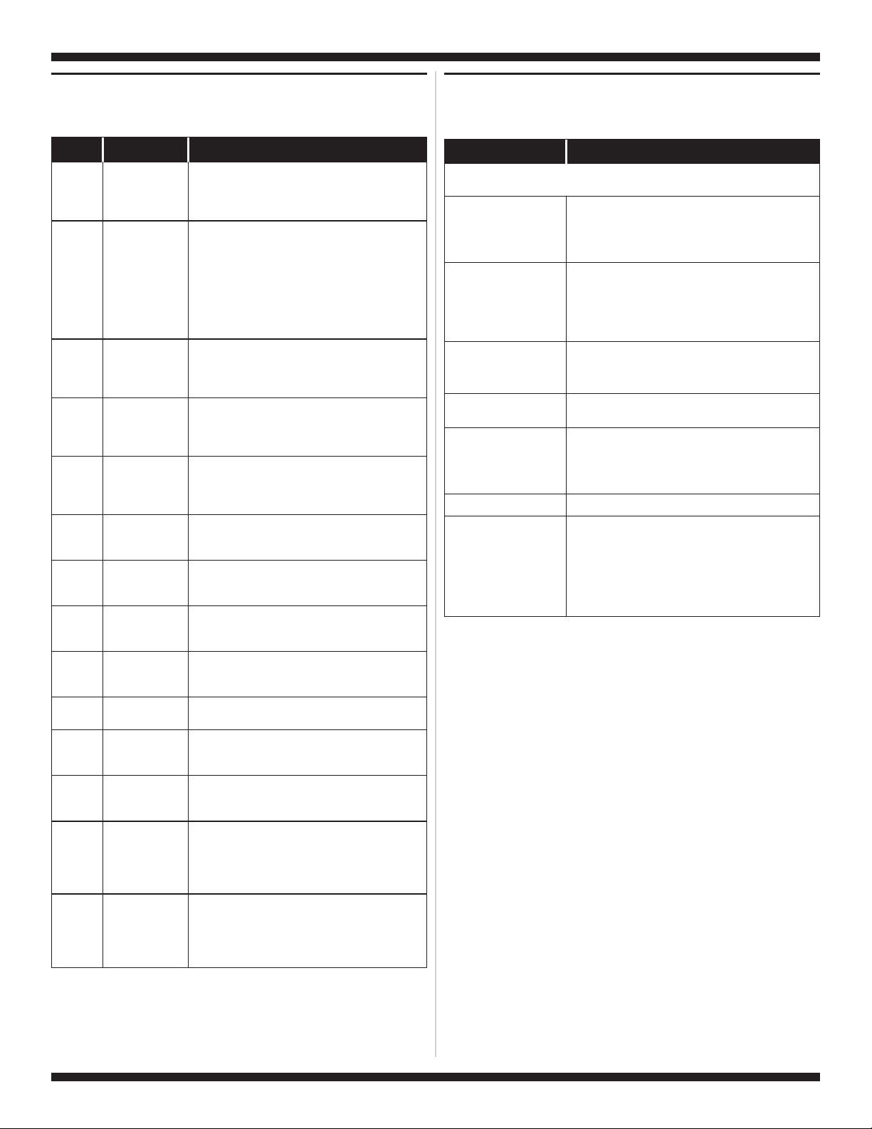
See Accessing & Removing the Electronic Assemblies,
page 9, to access:
■
Machine Control Electronics
User Interface Assembly
■
See Removing the
Back Panel, page 10,
to access:
■
Drum Light Assy.
Water Nozzle
Moisture
Door
Switch
Heater
Assembly
See Removing the Front Panel/Drum Assembly,
page 9, to access:
Moisture Sensors
■
Exhaust
■
Thermal Cut-off
■
Inlet Thermistor/
■
High Limit Thermostat
Sensor
Thermistor
Strips
■
■
■
■
■
■
Heater
Assembly
Thermal Fuse
(Steam Model)
Water Valve Assy.
(Steam Model)
Drive Motor
Belt Switch
Figure 2. Component locations.
TROUBLESHOOTING TESTS
NOTE: These checks are done with the dryer
unplugged or disconnected from power.
TEST #1 Supply Connections
This test should only be done after confirming proper
voltage at the outlet.
1. Unplug dryer or disconnect power.
2. Remove the cover plate from the back of the
dryer. See figure 3.
Cover
Plate
Figure 3. Remove the cover plate.
3. Make sure the power cord is securely fastened
to the terminal block.
4. With an ohmmeter, check for continuity between
the neutral (N) terminal of the plug and the center
contact on the terminal block. See figure 4.
Remove Screw
Power Cord
Plug
N
COM
Terminal Block
L1
Figure 4. Plug-to-terminal connections.
➔ If there is no continuity, replace the power cord
and test the dryer.
➔ If there is continuity, go to step 5.
5. In a similar way, check which terminal of the plug
is connected to the left-most contact on the
terminal block and make a note of it. This will be
L1 (black wire) in the wiring diagram. See figure 4
above and the appropriate wiring diagram. See
pages 11 and 12.
➔ When this is found, go to step 6.
➔ If neither of the plug terminals have continuity
with the left-most contact of the terminal
block, replace the power cord and test the
dryer.
6. Access the machine control electronics without
disconnecting any wiring to the control board.
See Accessing & Removing the Electronic
Assemblies, page 9.
7. With an ohmmeter, check for continuity between
the L1 terminal of the plug (found in step 5) and
P9-2 (black wire) on the machine control board.
See figure 16, page 9.
➔ If there is continuity, go to step 8.
➔ If there is no continuity, check that wires to the
terminal block are mechanically secure. If so,
replace the main wire harness and test the dryer.
8. Check for continuity between the neutral (N)
terminal of the plug and P8-3 (white wire) on the
machine control board.
➔ If there is continuity, go to step 9.
➔ If there is no continuity and the mechanical
connections of the wire are secure, replace the
main wire harness.
9. Visually check that the P5 connector is inserted
all the way into the machine control electronics.
10. Visually check that the user interface assembly
is properly inserted into the front console.
11. If both visual checks pass, replace the user
interface assembly.
12. Replace all parts and panels.
13. Plug in dryer or reconnect power.
14. Perform the Console Buttons and Indicators
Diagnostic test, page 1, to verify repair.
15. If indicators still do not light, the machine control
electronics has failed:
➔ Unplug dryer or disconnect power.
➔
Replace the machine control electronics.
➔
Replace all parts and panels.
➔
Plug in dryer or reconnect power.
➔
Perform the Console Buttons and Indicators
Diagnostic test, page 1 to verify repair.
TEST #2 Machine Control Power Check
This test is used to determine if power is present at
the machine control electronics.
NOTE: The drum light is controlled by the machine
control on all models.
1. Plug in dryer or reconnect power.
2. Open the door.
If the drum light illuminates, then power is
➔
present at the machine control. Go to
TEST #6, page 8.
➔ If the drum light fails to illuminate, do not
assume the machine control electronics needs
replacement. Several conditions may cause
the drum light not to illuminate, including a bad
bulb. If the drum light does not illuminate, go
to TEST #1, at left.
TEST #3 Drive Motor Circuit
This test will check the wiring to the motor and the
motor itself. The following items are part of this
motor system:
– Harness/
connection
– Thermal fuse
– Belt/belt switch
– Drive motor
1. Unplug dryer or disconnect power.
2. Access the machine control electronics and
measure the resistance across P8-4 and P9-1.
See Accessing & Removing the Electronic
Assemblies, page 9.
➔ If resistance across P8-4 and P9-1 is in the
range of 1 to 6 Ω, replace the machine control
electronics.
➔ Otherwise, go to step 3.
3. Check the wiring and components in the path
between these measurement points by referring
to the appropriate wiring diagram. See pages 11
and 12.
4. Perform TEST #4b, page 7. If thermal fuse is OK,
continue with step 5.
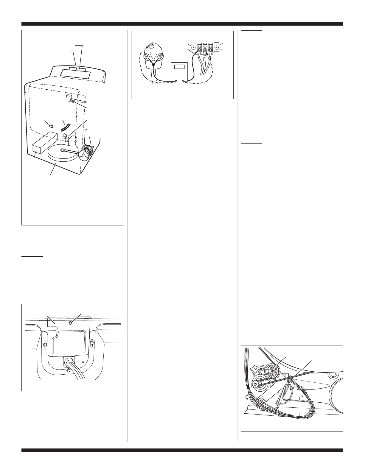
5. Check the belt switch and drive motor. Access the
belt switch and drive motor by removing the back
panel. See Removing the Back Panel, page 10.
Slowly remove the drum belt from the
spring-loaded belt switch tension pulley, gently
letting the pulley down. See figure 5.
Figure 5. Slowly remove drum belt.
– Centrifugal switch
– Door switch
– Machine control
electronics. See ESD
information, page 1.
Tension
Pulley
Drum
Belt
W10301482B .ON TRAPYLNO ESU S’NAICINHCET ECIVRES ROF
 Loading...