

Whirlpool WEC310SAGB Wiring Sheet
W11241247A
For controls
NOTE: This sheet contains important Technical Service Data.
FOR SERVICE TECHNICIAN ONLY
DO NOT REMOVE OR DESTROY
FOR SERVICE TECHNICIAN’S USE ONLY
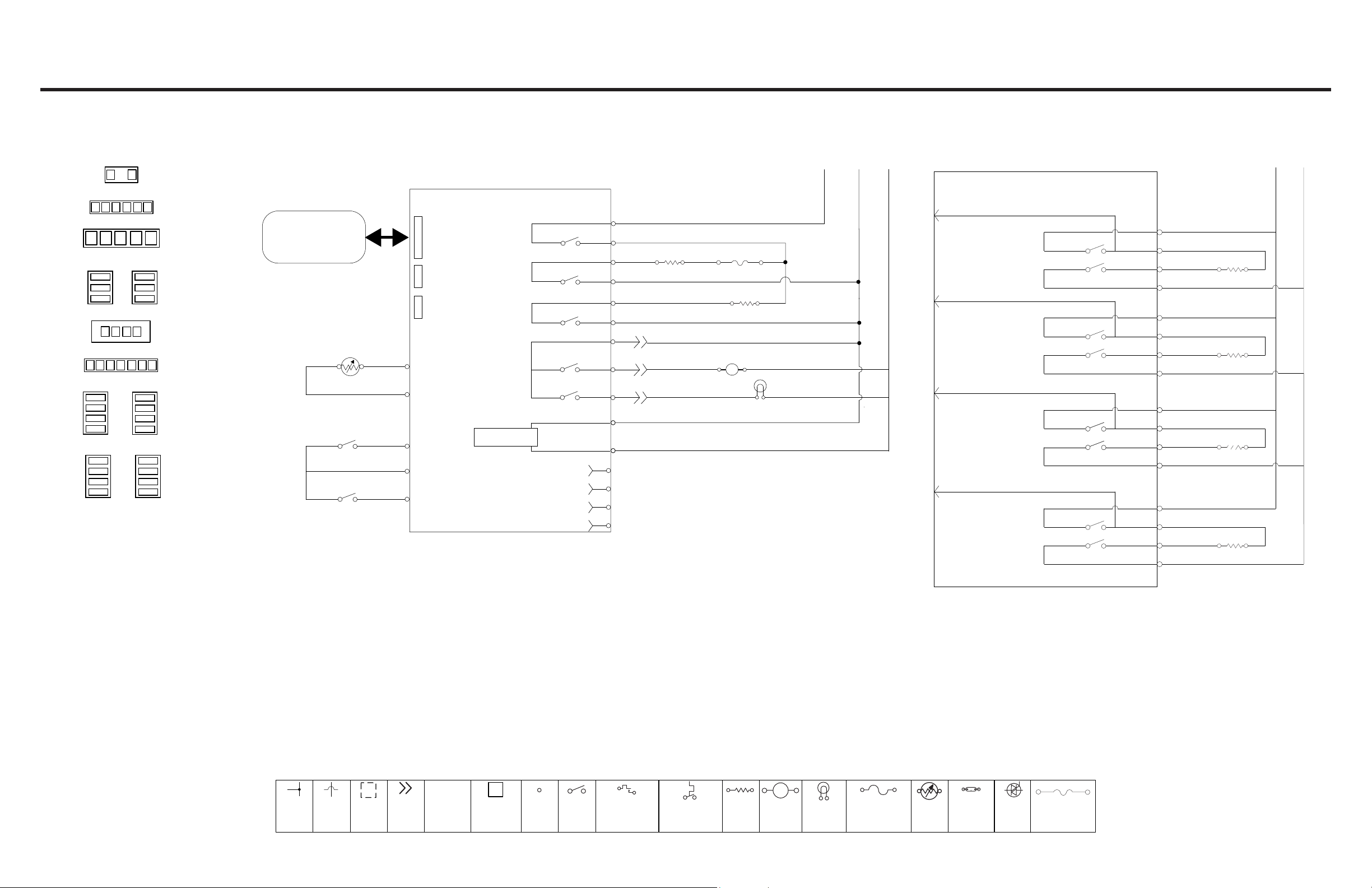
Wiring Diagram
Do Not Remove Or Destroy
Quick Connect Plugs
P1 through P10 for oven controls
P21 through P25 for cooktop
P1 (Red)
WH
BK
1
P2 (Blue)
WHBR
BU
GY YL
P5 (Blue)
RD
4
BK
3
BU
1
1
P21
YLBU
P23 (Black)
4
OR
3
BR
2
1
RD
P25 (Yellow)
4
YL
3
RD
2
1
BU
1
1
1
BK
P3 (Red)
V
V
P4 (Red)
BK
4
BK
3
RD
1
P10 (Yellow)
BK
P22 (White)
4
BR
3
BK
2
1
P24 (Green)
4
OR
3
BK
2
1
RD
Membrane
Keypad
Main Oven Temp
Sensor (RTD)
Oven Lock Motor Switch
Door Position Switch
Oven Control Wiring Diagram
Oven Control LCX 1.5
P11
Keypad
P7
Not Used
P9
Not Used
P3-5
V
RTD Oven
P3-4
V
RTD Common
P3-3
BU
P3-2
GY
Switch Common
P3-1
YL
Power Supply
Cooktop Feedback
DLB (P6)
K1
Broil (P5)
K2
Bake (P4)
K3
K5
K4
P4-1
P5-4
P5-1
P5-3
P4-3
P4-4
P2-6
P2-3
P2-1
P1-1
Power In (P1)
P1-3
P10-4
P10-3
P10-2
P10-1
RD
RD
BU
BK
BK
BK
BK
BR
WH
BK
WH
Broil 3400W
NOTE: Schematic shows oven door open and elements off.
N
WH
BU/WH
Thermo Fuse
363°F (184°C)
Opens at
RD
L2 L1
RD
BK
Bake 2400W
Oven Lock Motor
M
Oven Light 40W
P10-2
P10-1
P10-4
P10-3
Cooktop Wiring Diagram
Oven Control LCX 1.5 (Cont.)
P25-3
K9
K8
K12
K10
K14
K13
K17
K15
P25-4
P21-4
P21-7
P24-1
P23-4
P24-4
P24-3
P25-3
P25-1
P21-5
P21-7
P23-1
P23-3
P22-4
P22-3
RD
YL
YL
BK
RD
OR
OR
BK
RD
BU
BU
BK
RD
BR
BR
BK
RD
1300W (LF)
2150W (LR)
1300W (RR)
2150W (RF)
L2 L1
BK
W11241247A
Connection
No
Connection
On Some
Models
Connection
In Line
P2-1
Connector P2,
Position 1
Circuit ry
Enclosed Within
Terminals
Single
Switch
LEGEND
The rmal Switch
(opens on heat rise)
©2018. All rights reserved.
The rmal Switch
(closes on heat rise)
Resistor or
Element
M
Motor
Incandescent
Light
Non-resetta ble Fuse
The rmistor
Indicator Light
Triac
Thermo Fuse
04/18
 Loading...