

Whirlpool WDE350LVS02, WDE350LVQ02, WDE350LVB02 Installation Guide
INSTALLATIONINSTRUCTIONS
DROP-IN ELECTRICRANGE
Table of Contents
RANG E SAFETY ............................................................................. 1
INSTALLATION REQUIREMENTS ................................................ 2
Tools and Parts ............................................................................ 2
Location Requirements ................................................................ 2
Electrical Requirements ............................................................... 4
Countertop Preparation ............................................................... 4
INSTALLATION INSTRUCTIONS .................................................. 4
Unpack Range ............................................................................. 4
Install Anti-Tip Bracket ................................................................. 5
Adjust Leveling Legs .................................................................... 5
Electrical Connection ................................................................... 6
Verify Anti-Tip Bracket Is Installed and Engaged ........................ 7
Level Range ................................................................................. 7
Install Lower Trim ......................................................................... 7
Complete Installation ................................................................... 7
Moving the Range ........................................................................ 8
RANGESAFETY
Your safety and the safety of others are very important.
We have provided many important safety messages in this manual and on your appliance. Always read and obey all safety
messages.
This is the safety alert symbol.
This symbol alerts you to potential hazards that can kill or hurt you and others.
All safety messages will follow the safety alert symbol and either the word "DANGER" or "WARNING."
These words mean:
You can be killed or seriously injured if you don't immediately
follow instructions.
You can be killed or seriously injured if you don't follow
instructions.
All safety messages will tell you what the potential hazard is, tell you how to reduce the chance of injury, and tell you what can
happen if the instructions are not followed.
iMPORTANT:
Save for local electrical inspector's use.
W10430948A
Iq Anti-Tip
Ra_ '''Bracket
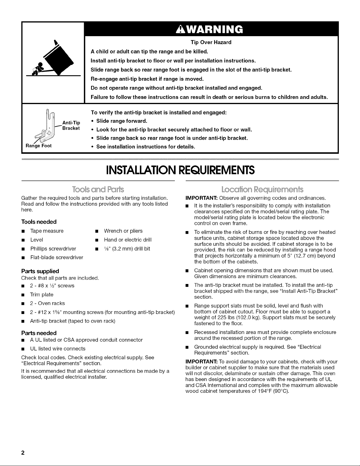
TipOverHazard
Achildoradultcantiptherangeandbekilled.
Installanti-tipbrackettofloor or wall per installation instructions.
Slide range back so rear range foot is engaged in the slot of the anti-tip bracket.
Re-engage anti-tip bracket if range is moved.
Do not operate range without anti-tip bracket installed and engaged.
Failure to follow these instructions can result in death or serious burns to children and adults.
To verify the anti-tip bracket is installed and engaged:
• Slide range forward.
• Look for the anti-tip bracket securely attached to floor or wall.
• Slide range back so rear range foot is under anti-tip bracket.
• See installation instructions for details.
INSTALLATIONREQUIREMENTS
Gather the required tools and parts before starting installation.
Read and follow the instructions provided with any tools listed
here.
Tools needed
• Tape measure
• Level
• Phillips screwdriver
• Flat-blade screwdriver
Parts supplied
Check that all parts are included.
• 2 - #8 x 1/2"screws
• Trim plate
• 2- Oven racks
• 2 - #12 x 15/8"mounting screws (for mounting anti-tip bracket)
• Anti-tip bracket (taped to oven rack)
Parts needed
• A UL listed or CSA approved conduit connector
• UL listed wire connects
Check local codes. Check existing electrical supply. See
"Electrical Requirements" section.
It is recommended that all electrical connections be made by a
licensed, qualified electrical installer.
• Wrench or pliers
• Hand or electric drill
• 1/8"(3.2 mm) drill bit
IMPORTANT: Observe all governing codes and ordinances.
• It is the installer's responsibility to comply with installation
clearances specified on the model/serial rating plate. The
model/serial rating plate is located below the electronic
control on oven frame.
To eliminate the risk of burns or fire by reaching over heated
surface units, cabinet storage space located above the
surface units should be avoided. If cabinet storage is to be
provided, the risk can be reduced by installing a range hood
that projects horizontally a minimum of 5" (12.7 cm) beyond
the bottom of the cabinets.
• Cabinet opening dimensions that are shown must be used.
Given dimensions are minimum clearances.
• The anti-tip bracket must be installed. To install the anti-tip
bracket shipped with the range, see "Install Anti-Tip Bracket"
section.
Range support slats must be solid, level and flush with
bottom of cabinet cutout. Floor must be able to support a
weight of 225 Ibs (102.0 kg). Support slats must be securely
fastened to the floor.
• Recessed installation area must provide complete enclosure
around the recessed portion of the range.
• Grounded electrical supply is required. See "Electrical
Requirements" section.
IMPORTANT: To avoid damage to your cabinets, check with your
builder or cabinet supplier to make sure that the materials used
will not discolor, delaminate or sustain other damage. This oven
has been designed in accordance with the requirements of UL
and CSA International and complies with the maximum allowable
wood cabinet temperatures of 194°F (90°C).
2
Mobile Home - Additional Installation Requirements
The installation of this range must conform to the Manufactured
Home Construction and Safety Standard, Title 24 CFR, Part 3280
(formerly the Federal Standard for Mobile Home Construction
and Safety, Title 24, HUD Part 280). When such standard is not
applicable, the Standard for Manufactured Home Installations,
ANSI A225.1/NFPA 501A or with local codes.
Mobile home installations require:
• When this range is installed in a mobile home, it must be
secured to the floor during transit. Any method of securing
the range is adequate as long as it conforms to the standards
listed above.
• Four-wire cable must be used in a mobile home installation.
The appliance wiring will need to be revised. See "Electrical
Connection" section.
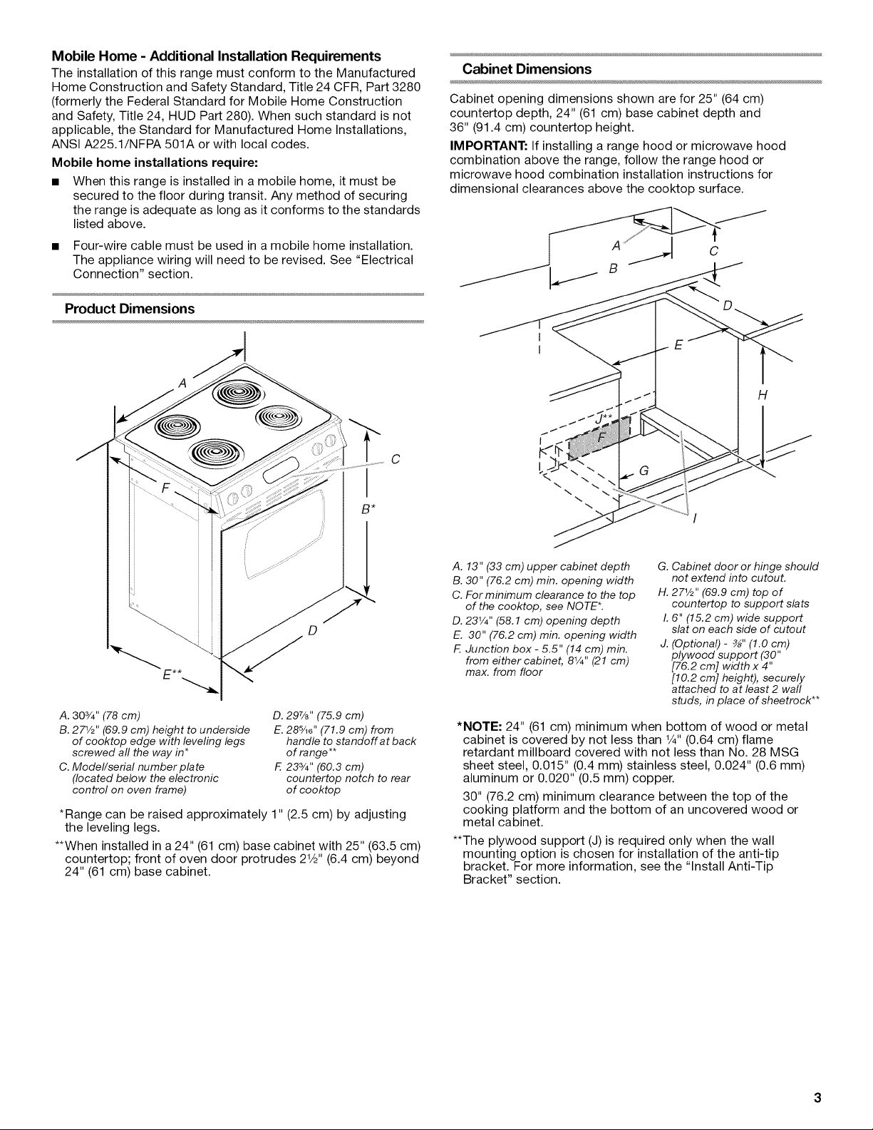
Product Dimensions
Cabinet Dimensions
Cabinet opening dimensions shown are for 25" (64 cm)
countertop depth, 24" (61 cm) base cabinet depth and
36" (91.4 cm) countertop height.
IMPORTANT: If installing a range hood or microwave hood
combination above the range, follow the range hood or
microwave hood combination installation instructions for
dimensional clearances above the cooktop surface.
1
I
H
C
I
B*
D
A. 303/4" (78 cm)
B. 271/2'' (69.9 cm) height to underside
of cooktop edge with leveling legs
screwed all the way in*
C. Model/serial number plate
(located below the electronic
control on oven frame)
*Range can be raised approximately 1" (2.5 cm) by adjusting
the leveling legs.
**When installed in a 24" (61 cm) base cabinet with 25" (63.5 cm)
countertop; front of oven door protrudes 21/2'' (6.4 cm) beyond
24" (61 cm) base cabinet.
D. 297/8'' (75.9 cm)
E.285/16'' (71.9 cm) from
handle to standoff at back
of range **
F. 233/4'' (60.3 cm)
countertop notch to rear
of cooktop
I
A. 13" (33 cm) upper cabinet depth
B. 30" (76.2 cm) min. opening width
C. For minimum clearance to the top
of the cooktop, see NOTE*.
D. 231/4''(58.1 cm) opening depth
E. 30" (76.2 cm) min. opening width
F. Junction box - 5.5" (14 cm) min.
from either cabinet, 81/4'' (21 cm)
max. from floor
G. Cabinet door or hinge should
not extend into cutout.
H. 271/2" (69.9 cm) top of
countertop to support slats
I. 6" (15.2 cm) wide support
slat on each side of cutout
J. (Optional) - _" (1.0 cm)
plywood support (30"
[76.2 cm] width x 4"
[10.2 cm] height), securely
attached to at least 2 wall
studs, in place of sheetrock**
*NOTE: 24" (61 cm) minimum when bottom of wood or metal
cabinet is covered by not less than 1/4"(0.64 cm) flame
retardant millboard covered with not less than No. 28 MSG
sheet steel, 0.015" (0.4 mm) stainless steel, 0.024" (0.6 mm)
aluminum or 0.020" (0.5 mm) copper.
30" (76.2 cm) minimum clearance between the top of the
cooking platform and the bottom of an uncovered wood or
metal cabinet.
**The plywood support (J) is required only when the wall
mounting option is chosen for installation of the anti-tip
bracket. For more information, see the "Install Anti-Tip
Bracket" section.
 Loading...