

Whirlpool WCG55US6HS, WCG55US6HB, WCG97US0HS, WCG77US0HS, WCG55US0HS INSTALLATION INSTRUCTIONS AND OPERATION MANUAL
...Page 1

PROPANE GAS CONVERSION INSTRUCTIONS
IMPORTANT:
Installer:
Homeo
For WCG, MGC, KCGS and ICS5/6 Model Series
INSTRUCTIONS DE CONVERSION AU GAZ
PROPANE
Pour les modèles de série WCG, MGC, KCGS et ICS5/6
Table of Contents Table des matières
COOKTOP SAFETY ........................................................................2
Tools and Parts .............................................................................3
Convert from Natural Gas to Propane Gas .................................3
Convert from Propane Gas to Natural Gas .................................6
Lighting the Electronic Igniters ....................................................9
Flame Height Adjustment.............................................................9
Complete Burner Adjustment ....................................................10
SÉCURITÉ DE LA TABLE DE CUISSON .....................................12
Outils et pièces ...........................................................................13
Conversion du gaz naturel au propane ......................................13
Conversion pour changement de gaz propane au gaz naturel .16
Allumeurs électroniques - allumage...........................................19
Réglage de la taille des flammes ...............................................19
Achever le réglage des brûleurs ................................................20
IMPORTANT :
Installateur : Remettre les instructions d’installation au propriétaire.
Propriétaire : Conserver les instructions d’installation pour référence
ultérieure.
W11168236B
Leave installation instructions with the homeowner.
wner: Keep installation instructions for future reference.
Page 2
COOKTOP SAFETY
WARNING: Gas leaks cannot always be detected by smell.
Gas suppliers recommend that you use a gas detector approved by UL or CSA.
For more information, contact your gas supplier.
If a gas leak is detected, follow the “What to do if you smell gas” instructions.
Your safety and the safety of others are very important.
We have provided many important safety messages in this manual and on your appliance. Always read and obey all safety
messages.
This is the safety alert symbol.
This symbol alerts you to potential hazards that can kill or hurt you and others.
All safety messages will follow the safety alert symbol and either the word “DANGER” or “WARNING.”
These words mean:
You can be killed or seriously injured if you don't immediately
DANGER
WARNING
All safety messages will tell you what the potential hazard is, tell you how to reduce the chance of injury, and tell you what can
happen if the instructions are not followed.
WARNING: If the information in these instructions is not followed exactly, a fire or
explosion may result causing property damage, personal injury or death.
follow instructions.
You
can be killed or seriously injured if you don't
instructions.
follow
– Do not store or use gasoline or other flammable vapors and liquids in the vicinity of this
or any other appliance.
– WHAT TO DO IF YOU SMELL GAS:
Do not try to light any appliance.
•
Do not touch any electrical switch.
•
Do not use any phone in your building.
•
Immediately call your gas supplier from a neighbor's phone. Follow the gas supplier's
•
instructions.
If you cannot reach your gas supplier, call the fire department.
•
– Installation and service must be performed by a qualified installer, service agency or
the gas supplier.
In the State of Massachusetts, the following installation instructions apply:
Installations and repairs must be performed by a qualified or licensed contractor, plumber, or gasfitter qualified or licensed by
the State of Massachusetts.
Acceptable Shut-off Devices: Gas Cocks and Ball Valves installed for use shall be listed.
A flexible gas connector, when used,must not exceed 4 feet (121.9 cm).
2
Page 3
4
A
B
C
A
Tools and Parts
Gather the required tools and parts necessary for correct
Propane gas conversion.
Tools needed
■ Flat-blade screwdriver
32
■ ³⁄
” (#0 [2.0 mm]) flat-blade screwdriver (screwdriver shaft
must be a minimum of 2” [5.1 cm] long)
■ Adjustable wrench
■ 7.0 mm nut driver
■ 7.0 mm wrench
■ T10 Torx
Parts needed
For models KCGS550ESS, KCGS556ESS, KCGS950ESS and
KCGS956ESS use the following parts:
For all other models use the following parts:
High Altitude Conversion
To convert the cooktop for elevations above 6,560 ft (1999.5 m),
order a High Altitude Conversion Kit.
For models KCGS550ESS, KCGS556ESS, KCGS950ESS and
KCGS956ESS use the following parts:
For all other models use the following parts:
To order, see the “Assistance or Service” section of the User
Guide.
IMPORTANT: Gas conversions from Natural gas to Propane
gas must be done by a qualified installer. Before proceeding
with conversion, shut off the gas supply to the cooktop prior to
disconnecting the electrical power.
This conversion kit shall be installed by a
qualified service agency in accordance
with the manufacturer's instructions and
all applicable codes and requirements of
the authority having jurisdiction. If the
information in these instructions is not
followed exactly, a fire, explosion or
production of carbon monoxide may
result causing property damage, personal
injury or loss of life. The qualified service
agency is responsible for the proper
installation of this kit. The installation is
not proper and complete until the
operation of the converted appliance is
checked as specified in the
manufacturer's instructions supplied with
this kit.
†®TORX and T10 is a registered trademark of Acument Intellectual Properties, LLC.
®†
adapter
■ Propane orifice package (W10676662)
■ Conversion instructions (W11168236)
■ Propane orifice package (W11173306)
■ Conversion instructions (W11168236)
■ Part Number W10679116 - Propane high altitude
■ Part Number W10679118 - Natural gas high altitude
■ Part Number W10679114 - Propane high altitude
■ Part Number W10679113 - Natural gas high altitude
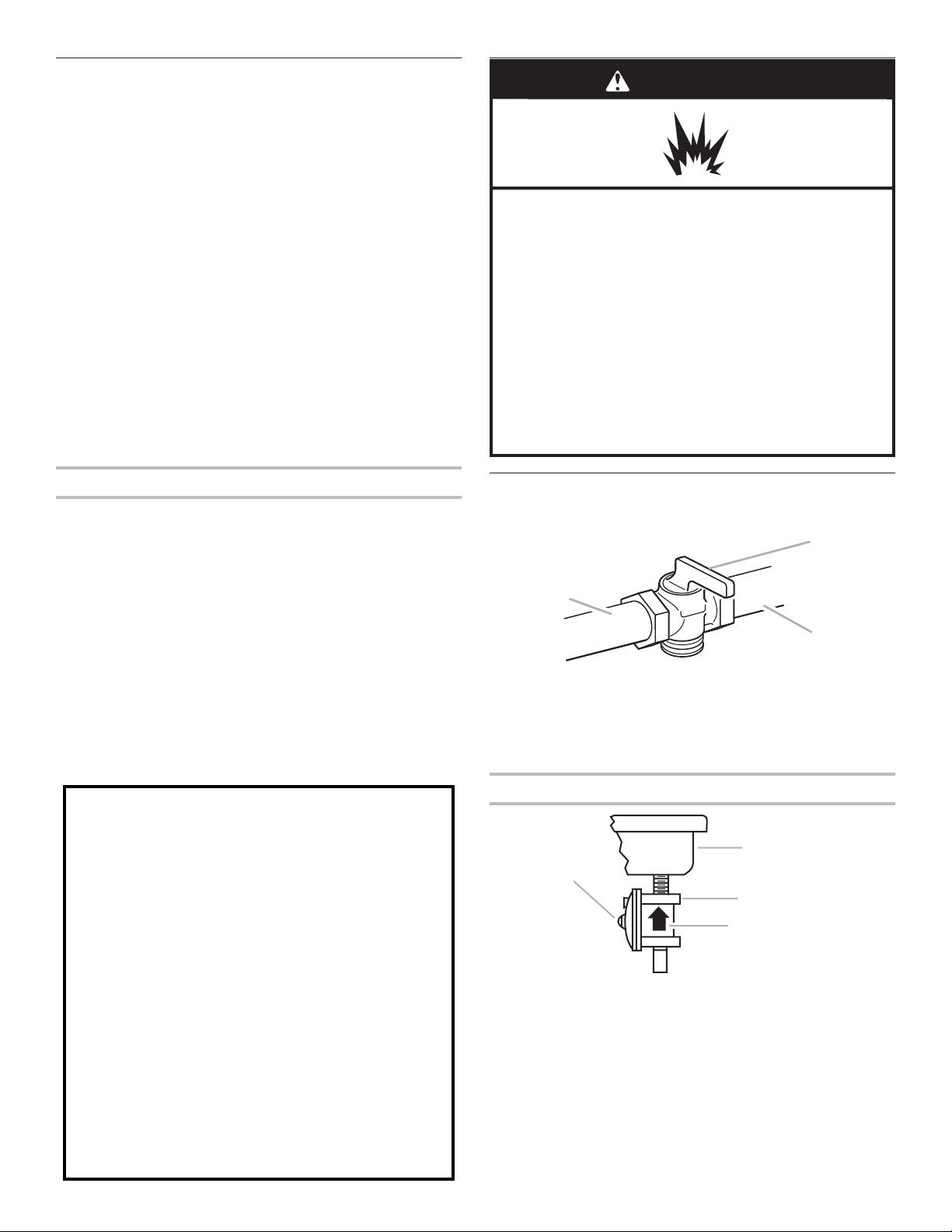
WARNING
WARNING
Explosion Hazard
Use a new CSA International approved gas supply line.
Install a shut-off valve.
Securely tighten all gas connections.
If connected to propane, have a qualified person make
sure gas pressure does not exceed 14" (36 cm) water
column.
Examples of a qualified person include:
licensed heating personnel,
authorized gas company personnel, and
authorized service personnel.
Failure to do so can result in death, explosion, or fire.
Convert from Natural Gas to Propane Gas
1. Turn manual shutoff valve to the closed position.
A. To cooktop
B. Shutoff valve (closed position)
C. Gas supply line
2. Unplug cooktop or disconnect power.
To Convert Gas Pressure Regulator
B
C
D
A. To cooktop
B. Shutoff valve (closed position)
C. Gas supply line
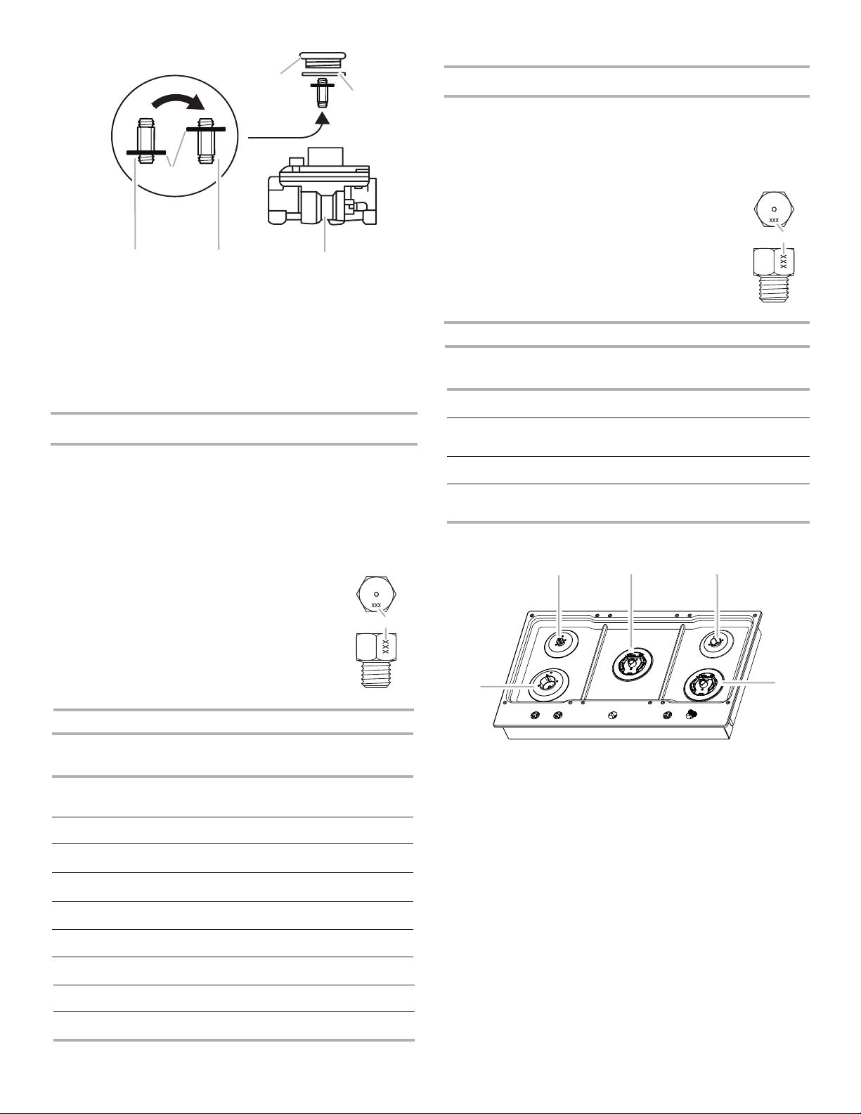
3. Determine the type of regulator you have:
Style 1: The cap has a slot and “NAT” printed on it.
Remove access cap by using a flat-blade screwdriver or
coin, turning the access cap counterclockwise.
3
Page 4
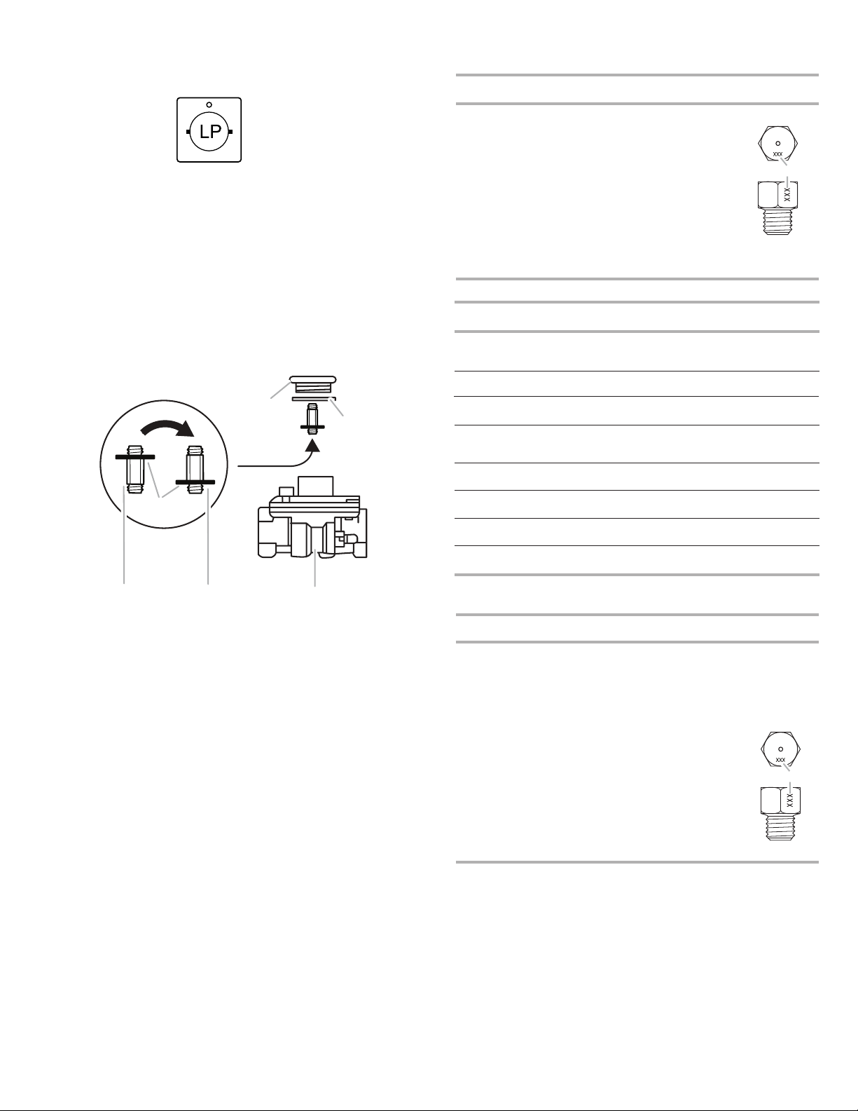
The gas pressure regulator has 2 settings that are stamped on
W
77
either side of the cap. Turn the cap and reinstall into regulator
with the stamp “LP” visible from the outside of the regulator.
Style 2: The access cap has a slot in it or a hex shape, without
any printed text.
Remove the access cap by using a flat - blade screwdriver or
wrench turning the access cap counter clockwise.
If Seven Universe is printed on the regulator, unthread the spring
retainer by rotating it counter clockwise. If Maxitrol is printed
on the regulator then apply force to the flat side of the spring
retainer to remove it.
Turn over the spring retainer to place the disk on the spring
retainer far from the access cap.
Install the Seven Universe spring retainer by turning it clockwise
to thread it fully into the access cap, or for the Maxitrol spring
retainer by applying pressure to snap the spring retainer into the
access cap.
Reinstall the cap and seal onto the regulator by turning
clockwise.
A
B
Propane Gas Orifice Spud Chart for Kit W10676661
Burner
Rating
5,000 BTU Green660.66 mm
7,000 BTU White750.75 mm
8,000 BTU Orange79 0.79 mm
11,000 BTURed 97 0.97 mm
13,000 BTUYellow 108 1.08 mm
16,000 BTUPink 115 1.15 mm
12,000 BTU
Inner
Outer
11,000 BTU
Inner
Outer
ColorStamp (A)Size
Brown
Brown
Black
Black
85
48
89
40
0.85 mm
0.48 mm
0.89 mm
0.40 mm
Burner Models for Kit W11173306
Model No.Left
WCG55US0H
MGC7430D
ICS500DS00
WCG77US0H
MGC9530D
KCGS350E
ICS655DS00
Front
66
Green
75
WhiteOrange YellowGreen
66 115N/A N/A9
Green
75
White79Orange85Brown48Brown66Green75White
Left
Rear
108
Ye llow
79
Pink
Center
Inner
Center
Outer
N/AN/A 97
108 N/A66
Right
Rear
Red75White
Re
A
A. Size stamp
Right
Front
75
White
d
5
White
WCG55US6H
MGC7536D
D
E
A. Access cap
B. Seal
C. Regulator
D. Disk on Spring Retainer
F
E. Spring Retainer in Natural Gas
Position
F. Spring Retainer in LP Gas
Position
C
4. Test the gas pressure regulator and gas supply line.
The regulator must be checked at a minimum 1” (2.5 cm)
water column above the set pressure. The inlet pressure to
the regulator should be as follows for operation and checking
the regulator setting:
Propane Gas:
Minimum pressure 10” (25.4 cm) W.C.P.
Supply pressure 14” (35.5 cm) W.C.P.
Gas Supply Pressure Testing
Line pressure testing above 1/2 psi (3.5 kPa) gauge
(14” [35.5 cm] WCP)
MGC9536D
KCGS356E
CG97US0H
WCG97US6H
Propane Gas Orifice Spud Chart for Kit W10676662
Burner
Rating
5,000 BTU
6,000 BTUGreen 70 0.70 mm
9,100 BTUBlac
11,000 BTU Orange 97
13,000 BTU
Inner
Outer
14,000 BTU
Inner
Outer
16,000 BTU
Inner
Outer
9,000 BTU
Inner
Outer
75
White75White
75
White75White85Brown48Brown66Green97Red
75
White79Orange89Black40Black66Green75White
75
White75White89BlackBlack
ColorStamp (A)Size
White
k890.89 mm
Blue
Brown
Blue
Ye llow
Blue
Red
Pink
Pink
97
Red
66 0.66 mm
45
97
45
101
45
105
40
80
N/A66
40 66
0.97 mm
0.45 mm
0.97 mm
0.45 mm
1.01 mm
0.45 mm
1.05 mm
0.40 mm
0.80 mm
Green97Red
Green97Red
A
A. Size stamp
The cooktop and its individual shutoff valve must be
disconnected from the gas supply piping system during any
pressure testing of that system at test pressures in excess of
½ psi (3.5 kPa).
Line pressure testing at 1/2 psi (3.5 kPa) gauge
(14” [35.5 cm] WCP) or lower
The cooktop must be isolated from the gas supply piping
system by closing its individual manual shutoff valve during
any pressure testing of the gas supply piping system at test
pressures equal to or less than ½ psi (3.5 kPa).
5. If the burner grates are installed, remove them.
Use the following charts to match the correct gas orifice
spud with the burner location and model being converted.
4
Page 5

Burner Models for Kit W10676662
Model No.Left
B
D
C
A
D
A
B
C
A
C
A
A
B
A
B
KCGS550E
KCGS556E
KCGS950ES
KCGS956ES
Front
Black66White45Blue97Brown70Green89Black
Black66white45Blue
Black66White45Blue97Brown70Green40Pink80Pink
Orange66White45Blue
89
89
89
97
Left
Rear
Center
Inner
Center
Outer
Yellow70Green89Black
Right
101
105
Red70Green40Pink80Pink
Rear
Right
Front
Inner
Right
Front
Outer
N/A
N/A
A
B
C
D
Burner locations
E
A. Left front
B. Left rear
C. Center
D. Right rear
E. Right front
6. Remove all burner caps and burner bases (see the User
Guide for burner reference).
To remove the burner base for the Dual Flame and Dual Tier
Ultra Torch burners use a Torx®† T10 driver to remove the
screw.
E
Torch Burner
A. Inner burner cap
B. Inner burner base
C. Outer burner base
D. Burner support
E. Gas tube opening
7. To Convert Standard Burner:
■ Use 7.0 mm wrench to loosen and remove the orifice
spud (A).
■ Set gas orifice spud aside.
■ Replace with correct Propane gas orifice spud. See
Propane gas orifice spud charts.
A. Orifice spud
Dual Tier Ultra Burner
A. Inner burner cap
B. Outer burner cap
C. Gas tube opening
D. Burner base
†®TORX and T10 is registered trademark of Acument Intellectual Properties, LLC.
B
D
8. To Convert Dual Tier Ultra and Dual Flame Burners:
■ Use 7.0 mm wrench to loosen and remove the inner
orifice spud (A) and the outer orifice spud (B).
■ Set gas orifice spuds aside.
■ Replace with correct Propane gas orifice spuds. See the
Propane gas orifice spud charts.
Standard and Dual Flame
A. Burner cap
B. Igniter electrode
C. Burner base
D. Gas tube opening
Dual Tier Ultra Burner
A. Inner orifice spud
B. Outer orifice spud
Standard and Dual Flame
A. Inner orifice spud
B. Outer orifice spud
5
Page 6
9. To Convert Torch Burner
C
B
C
A
B
C
A
B
C
■ Remove the spring that is shown in the following
illustration (C).
■ Use 7.0 mm wrench to loosen and remove the inner
orifice spud (A) and the outer orifice spud (B).
■ Set gas orifice spuds aside.
■ Replace with correct Propane gas orifice spud. See the
Propane gas orifice spud charts.
■ Return the spring to its original location.
A
B
A. Inner orifice spud
B. Outer orifice spud
C. Spring
IMPORTANT: Place Natural gas orifice spuds in
plastic parts bag for future use and keep with package
containing literature.
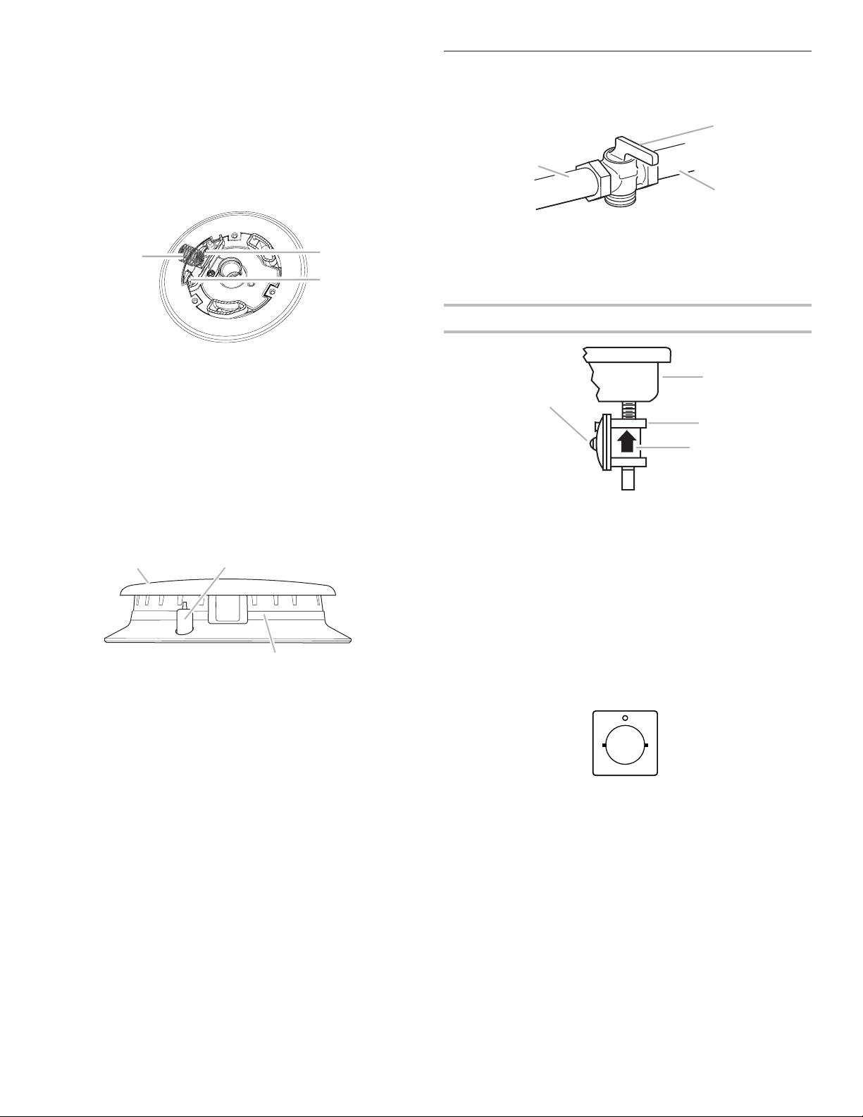
10. Replace sheet of insulation.
11. Replace burner bases and burner caps.
The igniter electrode is ceramic and could break during
conversion. Be sure that the electrode comes through the
hole in the burner smoothly while you are replacing the
burner base.
A
A. Burner cap
B. Electrode
C. Burner base
Convert from Propane Gas to Natural Gas
1. Turn manual shutoff valve to the closed position.
A. To cooktop
B. Shutoff valve (closed position)
C. Gas supply line
2. Unplug cooktop or disconnect power.
To Convert Gas Pressure Regulator
D
A. Access cap
B. Rear of cooktop
C. Gas pressure regulator
D. Gas flow
3. Determine the type of regulator you have:
Style 1: The cap has a slot and “LP” printed on it.
Remove access cap by using a flat-blade screwdriver or
coin, turning the access cap counterclockwise.
The gas pressure regulator has 2 settings that are stamped
on either side of the cap. Turn the cap and reinstall into
regulator with the stamp “NAT” visible from the outside of
the regulator.
12. Open shutoff valve in the gas supply line. The valve is open
NAT
when the handle is parallel to the gas pipe.
13. Plug in cooktop or reconnect power.
REMEMBER: Once you have completed converting all
of the cooktop burners, test the cooktop for leaks by
brushing on an approved noncorrosive leak-detection
solution. If bubbles appear, a leak is indicated. Correct any
leaks found.
14. To adjust single and dual valves, see the “Flame Height
Adjustment” section.
Style 2: The access cap has a slot in it or a hex shape,
without any printed text.
Remove the access cap by using a flat - blade screwdriver
or wrench turning the access cap counter clockwise.
If Seven Universe is printed on the regulator, unthread the
spring retainer by rotating it counter clockwise. If Maxitrol
is printed on the regulator then apply force to the flat side
of the spring retainer to remove it.
Turn over the spring retainer to place the disk on the spring
retainer close to the access cap.
Install the Seven Universe spring retainer by turning it
clockwise to thread it fully into the access cap, or for the
Maxitrol spring retainer by applying pressure to snap the
spring retainer into the access cap.
Reinstall the cap and seal onto the regulator by turning
clockwise.
6
Page 7
A
B
C
F
D
E
Natural Gas Orifice Spud Chart for Kit W11173306
Burner Models for Kit W11173306
Burner
Rating
Color Stamp (A)Size
5,000 BTU
Green
95 0.95 mm
A. Size stamp
9,100 BTUWhite or
no color
130 1.30 mm
10,000 BTUOrange 1351.35 mm
12,00 BTURed or
Blue
150 1.50 mm
15,000 BTUYellow 175 1.75 mm
18,00 BTUPink 189 1.89 mm
17,000 BTU
Inner
Outer
Red
Red
165
79
1.65 mm
0.79 mm
18,00 BTU
Inner
Outer
Brown
Brown
169
79
1.69 mm
0.79 mm
19,000 BTU
Inner
Outer
White
White
185
57
1.85 mm
0.57 mm
Model No.
Front
Left
Rear
Center
Inner
Center
Outer
Right
Rear
Right
Front
Inner
WCG55US0H
MGC7430D
ICS500DS00
95
Green
175
Yellow
N/AN/A 150
Red
130
White
WCG77US0H
MGC9530D
95
Green
189
Pink
N/AN/A 150
Red
130
White
WCG97US0H
KCGS350E
ICS655DS00
135
Orange
175
Red57Red95Green
WCG55US6H
MGC7536D
130
White
130
White
175
Yellow57Yellow95Green
150
Red
WCG97US6H
MGC9536D
130 130 169
Brown79Brown95Green
150
Blue
KCGS356E
130 130 185
White57White95Green
150
Red
A
Left
130
White
130
White
175 N/A95
Green
135
OrangeYellow
135
Orange
135
Orange
165 95
Green
135
Orange
Red
79
Red
130
White
130
White
White White
130 130 180
Brown57Brown95Green
150
RedWhite White
White White
Natural Gas Orifice Spud Chart for Kit W10676662
p
B
D
C
E
A
A. Access cap
B. Seal
C. Regulator
D. Disk on Spring Retainer
E. Spring Retainer in LP Gas
Position
F. Spring Retainer in Natural Gas
Position
4. If the burner grates are installed, remove them.
Use the following charts to match the correct gas orifice
spud with the burner location and model being converted.
Burner
Rating
6,000 BTU Red 105 1.05 mm
7,000 BTU Black115 1.15 mm
10,000 BTUWhite 140 1.40 mm
12,00 BTUBrown 150 1.50 mm
17,000 BTU
Inner
Other
18,000
Inner
Outer
20,000 BTU
Inner
Outer
10,000 BTU
Inner
Outer
ColorStamp (A)Size
Blue
Green
Blue
Blue
Blue
Light Blue91180
Pink
Pink
91
160
91
165
66
123
0.91 mm
1.60 mm
0.91 mm
1.65 mm
0.91 mm
1.80 mm
0.66 mm
1.23 mm
A
A. Size stam
Burner Models for Kit W10676662
Model No.Left
KCGS550E
KCGS556E
KCGS950ES
KCGS956ES
Front
White
White
White
Brown
140
140
140
150
Left
Center
Rear
Inner
105
Red91Blue
105
Red91Blue
105
Red91Blue
105
Red91Blue
Center
Outer
160
Green
180
Light
Blue
160
Green
180
Light
Blue
Right
Black
Black
Black67Pink
Black67Pink
Rear
115
115
115
115
Right
Front
Inner
140
White
140
white
Right
Front
Outer
N/A
N/A
125
Pink
125
Pink
Burner locations
A. Left front
B. Left rear
C. Center
D. Right rear
E. Right front
5. Remove all burner caps and burner bases (see the User
Guide for burner reference).
7
Page 8

To remove the burner base for the Dual Flame and Dual Tier
D
A
B
C
A
B
C
D
A
A
A
B
A
B
C
B
Ultra Torch burners use a Torx®† T10 driver to remove the screw.
Dual Tier Ultra Burner
A. Inner burner cap
B. Outer burner cap
C. Gas tube opening
D. Burner base
Standard and Dual Flame
A. Burner cap
B. Igniter electrode
C. Burner base
D. Gas tube opening
B
C
D
E
Dual Tier Ultra Burner
A. Inner orifice spud
B. Outer orifice spud
Standard and Dual Flame
A. Inner orifice spud
B. Outer orifice spud
8. To Convert Torch Burner
■ Remove the spring that is shown in the following
illustration (C).
■ Use 7.0 mm wrench to loosen and remove the inner
orifice spud (A) and the outer orifice spud (B).
■ Set gas orifice spuds aside.
■ Replace with correct Natural gas orifice spud. See the
Natural gas orifice spud charts.
■ Return the spring to its original location.
A
B
A. Inner orifice spud
B. Outer orifice spud
C. Spring
Torch Burner
A. Inner burner cap
B. Inner burner base
C. Outer burner base
D. Burner support
E. Gas tube opening
6. To Convert Standard Burner:
■ Use 7.0 mm wrench to loosen and remove the orifice
spud (A).
■ Set gas orifice spud aside.
■ Replace with correct Natural gas orifice spud. See
IMPORTANT: Place Natural gas orifice spuds in plastic
parts bag for future use and keep with package containing
literature.
9. Replace sheet of insulation.
10. Replace burner bases and burner caps.
The igniter electrode is ceramic and could break during
conversion. Be sure that the electrode comes through the
hole in the burner smoothly while you are replacing the
burner base.
A
Natural gas orifice spud charts.
A. Burner cap
B. Electrode
C. Burner base
A. Orifice spud
7. To Convert Dual Tier Ultra and Dual Flame Burners:
■ Use 7.0 mm wrench to loosen and remove the inner
orifice spud (A) and the outer orifice spud (B).
■ Set gas orifice spuds aside.
■ Replace with correct Natural gas orifice spuds. See the
Natural gas orifice spud charts.
†®TORX and T10 is a registered trademark of Acument Intellectual Properties, LLC.
8
11. Open shutoff valve in the gas supply line. The valve is open
when the handle is parallel to the gas pipe.
12. Plug in cooktop or reconnect power.
REMEMBER: Once you have completed converting all
of the cooktop burners, test the cooktop for leaks by
brushing on an approved noncorrosive leak-detection
solution. If bubbles appear, a leak is indicated. Correct any
leaks found.
13. To adjust single and dual valves, see the “Flame Height
Adjustment” section.
Page 9

Lighting the Electronic Igniters
B
C
A
A
B
The cooktop burners use electronic igniters in place of standing
pilots. When the cooktop control knob is pushed in, the system
creates a spark to light the burner. This sparking continues until
the control knob is turned to the desired setting.
To Check Operation of the Cooktop Burners:
1. Push in and turn knobs to the ignition position (see the User
Guide for additional information). The cooktop burner flame
should light within 4 seconds. The first time a burner is lit, it
may take longer than 4 seconds to light because of air in the
gas line. Do not leave the knob in the ignition position after
the burner lights.
2. If burners do not light properly, turn the control knob to the
Off position. Make sure the burner caps are in the proper
position.
3. Check that the power supply cord is plugged in. Check that
the circuit breaker has not tripped or the household fuse has
not blown.
4. Check that the shutoff valve is in the open position.
5. Check burner operation again.
If one or all of the burners do not light at this point, see
“Assistance or Service” section in the User Guide.
Flame Height Adjustment
A. ³⁄32” (#0 [2.0 mm]) flat-blade screwdriver
(screwdriver shaft must be a minimum of
2” [5.1 cm] long)
B. Control knob stem opening
C. Adjustment screw location
For Propane gas conversion:
Completely tighten screw “C” to set the inimum flame height.
For Natural gas conversion:
Tighten screw “C” to reduce flame height. Loosen screw to
increase flame height. See “Complete Burner Adjustment”
section.
4. Replace the control knob.
5. Test the flame by turning the control from LO to HI, checking
the flame at each setting.
Adjustment for Dual Valve
To Adjust Inner Crown Flame:
1. Set the inner crown flame to LO.
Each burner flame has been factory set to the lowest position
available to provide reliable and constant reignition of the burner.
However, each burner can be adjusted.
NOTE: If your model number begins with KGCS5 or KGCS9,
call service, as this operation will require opening the unit.
To Adjust:
The flame can be adjusted using the adjustment screws
underneath the control knob.
NOTE: Check the Use and Care Guide for information on each
burner to determine whether they are single or dual flame.
Adjust the valves accordingly.
Adjustment for Single Valve
1. Set the burner flame to LO.
2. Remove the control knob.
3. Hold knob stem with a pair of pliers. Use a ³⁄32” (#0 [2.0 mm])
flat-blade screwdriver to turn the screw located within the
shaft of the control knob stem until the flame is the proper
size.
2. Remove the control knob.
3. Remove the black rubber grommet.
4. Using needle-nose pliers, remove the gray shield inside the
burner valve opening.
A. Inner crown
B. Outer crown
d
e
M
A
B
C
A. Control knob
B. Black rubber grommet
C. Gray shield
9
Page 10

5. For Propane gas conversion:
B
A
B
Completely tighten screw “A” to set the minimum flame
height.
For Natural gas conversion:
Tighten screw “A” to reduce flame height. Loosen screw to
increase flame height. See “Complete Burner Adjustment”
section.
A. Inner crown adjustment screw
B. Outer crown adjustment screw
6. Replace the control knob.
To Adjust Outer Crown Flame:
1. Set the outer crown flame to LO.
2. Remove the control knob.
3. For Propane gas conversion:
Completely tighten screw “B” to set the minimum flame
height.
For Natural gas conversion:
Tighten screw “B” to reduce flame height. Loosen screw to
increase flame height. See “Complete Burner Adjustment”
section.
4. Replace the gray shield. Use a screwdriver to help push the
shield into place.
5. Replace the black rubber grommet.
6. Replace the control knob.
7. Test the flame by turning the control from LO to HI, checking
the flame at each setting.
Complete Burner Adjustment
1. Check burner flame(s) for a proper size and shape. The
cooktop low burner flame should be a steady blue flame
approximately ¹⁄4” (0.64 cm) high.
A
2. Completely fill out the conversion label and attach label to
bottom of the cooktop next to the rating tag. Do not cover
the rating tag with the conversion label.
IMPORTANT: Place gas orifice spuds in plastic parts bag for
future use and keep with package containing literature.
Read “Sealed Surface Burners” section in the Use and Care
Guide supplied with your cooktop.
10
Page 11

Notes
11
Page 12

SÉCURITÉ DE LA TABLE DE CUISSON
AVERTISSEMENT : L’odorat ne permet pas toujours la détection d’une fuite de gaz.
Les distributeurs de gaz recommandent l’emploi d’un détecteur de gaz (homologation UL ou CSA).
Pour d’autre information, contacter le fournisseur de gaz local.
En cas de détection d’une fuite de gaz, exécuter les instructions “Que faire dans le cas d’une odeur de gaz”.
Votre sécurité et celle des autres est très importante.
Nous donnons de nombreux messages de sécurité importants dans ce manuel et sur votre appareil ménager. Assurez-vous de
toujours lire tous les messages de sécurité et de vous y conformer.
Voici le symbole d’alerte de sécurité.
Ce symbole d’alerte de sécurité vous signale les dangers potentiels de décès et de blessures graves à vous
et à d’autres.
Tous les messages de sécurité suivront le symbole d’alerte de sécurité et le mot “DANGER” ou
“AVERTISSEMENT”. Ces mots signifient :
Risque possible de décès ou de blessure grave si vous ne
DANGER
AVERTISSEMENT
Tous les messages de sécurité vous diront quel est le danger potentiel et vous disent comment réduire le risque de blessure et
ce qui peut se produire en cas de non-respect des instructions.
AVERTISSEMENT : Si les renseignements dans ces instructions ne sont pas
exactement observés, un incendie ou une explosion peut survenir, causant des
dommages au produit, des blessures ou un décès.
suivez pas immédiatement les instructions.
Risque possible de décès ou de blessure grave si vous
ne suivez pas les instructions.
– Ne pas entreposer ni utiliser de l’essence ou d’autres vapeurs ou liquides inflammables
à proximité de cet appareil ou de tout autre appareil électroménager.
– QUE FAIRE DANS LE CAS D’UNE ODEUR DE GAZ :
Ne pas tenter d’allumer un appareil.
•
Ne pas toucher à un commutateur électrique.
•
Ne pas utiliser le téléphone se trouvant sur les lieux.
•
Appeler immédiatement le fournisseur de gaz à partir du téléphone d'un voisin. Suivre
•
ses instructions.
À défaut de joindre votre fournisseur de gaz, appeler les pompiers.
•
– L’installation et l’entretien doivent être effectués par un installateur qualifié, une agence
de service ou le fournisseur de gaz.
Dans l’État du Massachusetts, les instructions d’installation suivantes sont applicables :
■ Les travaux d’installation et réparation doivent être exécutés par un plombier ou tuyauteur qualifié ou licencié, ou par le
personnel qualifié d’une entreprise licenciée par l’État du Massachusetts.
■ Remplacer par des dispositifs de fermeture acceptables : Les robinets de gaz et robinets à bille installés pour l'utilisation
devraient être indiqués.
■ Si un conduit de raccordement flexible est utilisé, sa longueur ne doit pas dépasser 4 pi (121,9 cm).
12
Page 13

4
A
B
C
A
Outils et pièces
Rassembler les outils et pièces nécessaires pour l’exécution
correcte de la conversion pour l’alimentation au gaz propane.
Outils nécessaires
■ Tournevis à lame plate
■ Tournevis à tête plate de ³⁄
mesurer au moins 2” [5,1 cm] de long)
■ Clé à molette
■ Tourne-écrou de 7,0 mm
■ Clé de 7,0 mm
■ Adaptateur Torx
®†
T10
Pièces nécessaires
Pour les modèles KCGS550ESS, KCGS556ESS, KCGS950ESS
et KCGS956ESS, utiliser les pièces suivantes :
■ Sachet de gicleurs pour propane (W10676662)
■ Instructions de conversion (W11168236)
Pour les autres modèles, utiliser les pièces suivantes :
■ Sachet de gicleurs pour propane (W11173306)
■ Instructions pour la conversion (W11168236)
Conversion pour utilisation en haute altitude
Pour convertir la table de cuisson pour des altitudes supérieures
à 6 560pi (1999,5 m), commander un ensemble pour conversion
en haute altitude.
Pour les modèles KCGS550ESS, KCGS556ESS, KCGS950ESS
et KCGS956ESS, utiliser les pièces suivantes :
■ Pièce numéro W10679116 - gaz propane pour haute altitude
■ Pièce numéro W10679118 - gaz naturel pour haute altitude
Pour les autres modèles, utiliser les pièces suivantes :
■ Pièce numéro W10679114 - gaz propane pour haute altitude
■ Pièce numéro W10679113 - gaz naturel pour haute altitude
32
” (nº 0 [2 mm]) (la tige doit
AVERTISSEMENT
Risque d'explosion
Utiliser une canalisation neuve d'arrivée de gaz
approuvée par la CSA International.
Installer un robinet d'arrêt.
Bien serrer chaque organe de connexion de la
canalisation de gaz.
En cas de connexion au gaz propane, demander à une
personne qualifiée de s'assurer que la pression de gaz
ne dépasse pas 36 cm (14 po) de la colonne d'eau.
Par personne qualifiée, on comprend :
le personnel autorisé de chauffage,
le personnel autorisé d'une compagnie de gaz, et
le personnel d'entretien autorisé.
Le non-respect de ces instructions peut causer
un décès, une explosion ou un incendie.
Conversion du gaz naturel au propane
1. Fermer le robinet d'arrêt manuel.
Pour commander, voir la section “Assistance ou service” du
guide d’utilisation.
IMPORTANT : L'opération de conversion de l'appareil (pour
l'alimentation au gaz propane au lieu du gaz naturel) doit être
exécutée par un installateur qualifié. Avant d'entreprendre la
conversion, fermer l'arrivée de gaz à la table de cuisson avant
d'interrompre l'alimentation électrique de la table de cuisson.
AVERTISSEMENT
Cet ensemble de conversion doit être
installé par le personnel qualifié d'une
agence de service en conformité avec les
instructions du fabricant et les
prescriptions de tous les codes en vigueur
et des autorités juridictionnelles. Si les
présentes instructions ne sont pas
rigoureusement respectées, ceci peut
provoquer un incendie, une explosion ou
la génération de monoxyde de carbone
provoquant des dommages corporels ou
matériels, ou même la mort. La
responsabilité de l'installation correcte de
cet ensemble de conversion incombe au
personnel qualifié d'une agence de
service. L'installation n'est pas correcte et
complète avant que le bon fonctionnement
de l'appareil converti ait été vérifié sur la
base des spécifications présentées dans
les instructions du fabricant fournies avec
cet ensemble de pièces.
†®TORX et T10 est une marque déposée d’Acument Intellectual Properties, LLC.
A. Vers la table de cuisson
B. Robinet d’arrêt (position de
fermeture)
C. Canalisation d’alimentation en gaz
2. Débrancher la table de cuisson ou déconnecter la source de
courant électrique.
Conversion du détendeur
B
C
D
A. Vers la table de cuisson
B. Robinet d’arrêt (position de
fermeture)
C. Canalisation d’alimentation en gaz
3. Déterminer le type du détendeur :
Style 1 : Le chapeau comporte une rainure et la mention
“NAT”.
13
Page 14

Utiliser un tournevis à lame plate ou une pièce de monnaie
C
1
WCG55US0H
MGC7430D
ICS500DS00
WCG77US0H
MGC9530D
ICS655DS00
KCGS350E
WCG55US6H
MGC7536D
MGC9536D
KCGS356E
WCG97US0H
pour dévisser le chapeau de l’ouverture d’accès; faire
tourner le chapeau dans le sens antihoraire.
Deux réglages sont possibles pour le détendeur; l’information
correspondante est gravée de chaque côté du chapeau.
Orienter le chapeau correctement, et réinstaller le chapeau sur
le détendeur; la mention “LP” doit être visible à l'extérieur du
détendeur.
Style 2 : le capuchon d’accès comporte une fente ou une forme
hexadécimale, sans texte imprimé.
Retirez le capuchon d’accès à l’aide d’un tournevis ou d’une clé
à clé à plat tournant le capuchon d’accès dans le sens inverse
des aiguilles d’une montre.
Si Seven Universe est imprimé sur le régulateur, dévisser le
dispositif de retenue du ressort en le tournant dans le sens
inverse des aiguilles d’une montre. Si Maxitrol est imprimé sur
le régulateur, appliquez la force sur le côté plat du dispositif de
retenue du ressort pour l’enlever.
Tournez le dispositif de retenue du ressort pour placer le disque
sur le dispositif de retenue du ressort loin du capuchon d’accès.
Installez le dispositif de retenue du ressort de sept univers en
le tournant dans le sens des aiguilles d’une montre pour le
brancher complètement dans le capot d’accès ou pour le ressort
de ressort Maxitrol en appliquant une pression pour enfoncer le
dispositif de retenue du ressort dans le capuchon d’accès.
Réinstallez le capuchon et scellez le régulateur en tournant dans
le sens des aiguilles d’une montre.
La table de cuisson devra être isolée de la canalisation de
gaz par la fermeture du robinet d'arrêt manuel individuel
durant tout test de pressurisation de la canalisation de gaz à
une pression égale ou inférieure à ½ lb/po² (3,5 kPa).
5. Si les grilles de brûleur sont installées, les retirer.
Utiliser les tableaux qui suivent pour choisir le gicleur approprié selon
le modèle de l’appareil et l’emplacement du brûleur à convertir.
Tableau des gicleurs pour gaz propane pour ensemble W1067666
Puissance
thermique
5 000 BTU
7 000 BTU
8 000 BTU
11 000 BTU
13 000 BTU
16 000 BTU
12 000 BTU
Interne
Externe
11 000 BTU
Interne
Externe
Couleur Empreinte
Vert
Blanc
Orange
Rouge
Jaune
Rose
Marron
Marron8548
Noir
Noir
(A)
66
75
79
97
108
115
89
40
Taille
0,66 mm
0,75 mm
0,79 mm
0,97 mm
1,08 mm
1,15 mm
0,85 mm
0,48 mm
0,89 mm
0,40 mm
A
A. Empreinte
de la taille
Modèles de brûleur pour ensemble W11173306
Modèle n°
Avant
gauche
Vert
66
Arrière
gauche
108
Jaune
Centre
Interne
N/A N/A 97
Centre
Externe
Arrière
droit
Rouge75Blanc
Avant
droit
A. Capuchon d’accès
B. Sceau
C. Régulateur
D. Disk on Spring Retainer
4. Tester le détendeur et la canalisation de gaz.
A
B
D
E
F
E. Retenue de printemps en
position de gaz naturel
F. Spring Retainer dans la
position du gaz LP
On doit tester le détendeur sous une pression supérieure
d’au moins 1” (2,5 cm) de colonne d’eau à la pression de
service. Pour le fonctionnement et le contrôle du réglage du
détendeur, il faut que la pression d’admission au détendeur
corresponde aux indications ci-dessous :
Gaz propane :
Pression minimale de 10” (25,4 cm) (colonne d'eau)
Pression de service 14” (35,5 cm) (colonne d'eau)
Essai de pression de la canalisation de gaz
Mise sous pression à une pression supérieure à 1/2 lb/
po² (3,5 kPa) (14” [35,5 cm] de colonne d'eau)
Pour tout test de pressurisation du système à une pression
supérieure à ½ lb/po² (3,5 kPa), on doit déconnecter la table de
cuisson et son robinet d'arrêt de la canalisation à pressuriser.
Mise sous pression à une pression de 1/2 lb/po² (3,5 kPa)
(14” [35,5 cm] de colonne d'eau) ou moins
WCG97US6H
75
Blanc
66
Vert
75
Blanc79Orange85Marron48Marron66Vert75Blanc
75
Blanc75Blanc
75
Blanc75Blanc85Marron48Marron66Vert
75
Blanc79Orange89Noir
75
Blanc75Blanc89Noir
79
Vert
115
Rose
108 N/A 66
Jaune
N/A N/A 97
97
Rouge
N/A 66
40
Noir66Vert
40
Noir66Vert
Vert
Rouge75Blanc
Vert
75
Blanc
97
Rouge
97
Rouge
75
Blanc
97
Rouge
Tableau des gicleurs pour gaz propane pour ensemble W10676662
Puissance
thermique
5 000 BTU
6 000 BTU
9 100 BTU
11 000 BTU
13 000 BTU
Interne
Externe
14 000 BTU
Interne
Externe
16 000 BTU
Interne
Externe
9 000 BTU
Interne
Couleur Empreinte
Blanc
Vert
Noir
Orange
Bleu
Marron4597
Bleu
Jaune
Bleu
Rouge
Rose
(A)
66 0,66 mm
70
89
97
45
101
45
105
40
Taille
0,70 mm
0,89 mm
0,97 mm
0,45 mm
0,97 mm
0,45 mm
1,01 mm
0,45 mm
1,05 mm
0,40 mm
A
A. Empreinte
de la taille
14
Page 15

Modèles de brûleur pour ensemble W10676662
Modèle n°
B
D
C
A
D
A
B
C
A
C
A
A
B
A
B
KCGS550E
KCGS556E
KCGS950ES
KCGS956ES
Arrière
gauche
Centre
Interne
Avant
gauche
89
Noir66Blanc45Bleu97Marron70Vert89Noir
89
Noir66blanc45Bleu
89
Noir66Blanc45Bleu97Marron70Vert40Rose80Rose
97
Orange66Blanc45Bleu
Centre
Externe
Jaune70Vert89Noir
Arrière
101
105
Rouge70Vert40Rose80Rose
droit
Avant
droit
Interne
Externe
Avant
droit
N.D.
N.D.
A
B
C
D
Emplacement des brûleurs
A. Avant gauche
B. Arrière gauche
C. Central
D. Arrière droit
E. Avant droit
6. Retirer tous les chapeaux et les bases des brûleurs
(consulter le Guide d'utilisation pour des informations sur les
brûleurs).
Pour retirer la base des brûleurs à couronne double et des
brûleurs torches Dual Tier Ultra, utiliser un tournevis Torx®†
T10 pour retirer la vis.
E
Brûleur torche
A. Chapeau du brûleur interne
B. Base du brûleur interne
C. Base du brûleur externe
D. Support du brûleur
E. Ouverture du tube d’arrivée de gaz
E
7. Conversion du brûleur standard :
■ À l’aide d’une clé de 7 mm, desserrer et retirer le gicleur (A).
■ Conserver à part le gicleur du brûleur.
■ Remplacer le gicleur par un gicleur pour gaz propane de
taille correcte. Voir les tableaux de sélection des gicleurs
pour gaz propane.
A. Gicleur
B
Brûleur Dual Tier Ultra
A. Chapeau du brûleur
interne
B. Chapeau du brûleur
externe
C. Ouverture du tuyau de gaz
D. Base du brûleur
Standard et double amme
A. Chapeau de brûleur
B. Électrode d’allumeur
C. Base du brûleur
D. Ouverture du tuyau de gaz
†®TORX et T10 est une marque déposée d’Acument Intellectual Properties, LLC.
D
8. Conversion des brûleurs Dual Tier Ultra et à double
flamme :
■ À l’aide d’une clé de 7 mm, desserrer et retirer le gicleur
intérieur (A) et le gicleur extérieur (B).
■ Conserver à part les gicleurs de brûleur.
■ Remplacer les gicleurs par des gicleurs pour gaz
propane de taille correcte. Voir les tableaux de sélection
des gicleurs pour gaz propane.
Brûleur Dual Tier Ultra
A. Gicleur interne
B. Gicleur externe
Standard et double amme
A. Gicleur interne
B. Gicleur externe
15
Page 16

9. Conversion du brûleur torche
C
B
C
A
B
C
A
B
C
■ Retirer le ressort tel qu’indiqué sur l'illustration suivante
(C).
■ À l’aide d’une clé de 7 mm, desserrer et retirer le gicleur
intérieur (A) et le gicleur extérieur (B).
■ Conserver à part les gicleurs de brûleur.
■ Remplacer le gicleur par un gicleur pour gaz propane de
Conversion pour changement de gaz
propane au gaz naturel
1. Fermer le robinet d'arrêt manuel.
taille correcte. Voir les tableaux de sélection des gicleurs
pour gaz propane.
■ Replacer le ressort dans son emplacement d’origine.
A. Vers la table de cuisson
A
B
2. Débrancher la table de cuisson ou déconnecter la source de
B. Robinet d’arrêt (position de fermeture)
C. Canalisation d’alimentation en gaz
courant électrique.
Conversion du détendeur
A. Gicleur interne
B. Gicleur externe
C. Ressort
IMPORTANT : Placer les gicleurs pour gaz naturel
dans le sachet de pièces en plastique et les conserver
avec le sachet de documentation, pour pouvoir les
réutiliser ultérieurement.
10. Replacer la feuille isolante.
11. Replacer les bases et chapeaux de brûleur.
L'électrode d'allumage est en céramique et peut se briser
durant l'opération de conversion. Lorsque l'on réinstalle la
base du brûleur, veiller à ce que l'électrode traverse sans
difficulté le trou dans le brûleur.
A
A. Chapeau de l'ouverture d'accès
B. Arrière de la table de cuisson
C. Détendeur
D. Sens de circulation du gaz
3. Déterminer le type du détendeur :
Style 1 : Le chapeau comporte une rainure et la mention
“LP”.
Utiliser un tournevis à lame plate ou une pièce de monnaie
pour dévisser le chapeau de l’ouverture d’accès; faire
tourner le chapeau dans le sens antihoraire.
A. Chapeau de brûleur
B. Électrode
C. Base du brûleur
12. Ouvrir le robinet d’arrêt de la canalisation de gaz. Le robinet
Deux réglages sont possibles pour le détendeur;
l’information correspondante est gravée de chaque côté du
chapeau. Orienter le chapeau correctement, et réinstaller le
chapeau sur le détendeur; la mention “NAT” doit être visible
à l'extérieur du détendeur.
est ouvert lorsque la manette est parallèle au conduit
d’alimentation en gaz.
13. Brancher la table de cuisson ou reconnecter la source de
NAT
courant électrique.
NE PAS OUBLIER : Après avoir exécuté la conversion
de chaque brûleur de la table de cuisson, effectuer un
test de recherche des fuites en appliquant une solution
homologuée (non corrosive) pour détection des fuites sur
les connexions du circuit de gaz. L’apparition de bulles
indique une fuite. Éliminer toute fuite détectée.
14. Pour régler les robinets simples et doubles, consulter la
section “Réglage de la taille des flammes”.
Style 2 : le capuchon d’accès comporte une fente ou une
forme hexadécimale, sans texte imprimé.
Retirez le capuchon d’accès à l’aide d’un tournevis ou
d’une clé à clé à plat tournant le capuchon d’accès dans le
sens inverse des aiguilles d’une montre.
Si Seven Universe est imprimé sur le régulateur, dévisser le
dispositif de retenue du ressort en le tournant dans le sens
inverse des aiguilles d’une montre. Si Maxitrol est imprimé
sur le régulateur, appliquez la force sur le côté plat du
dispositif de retenue du ressort pour l’enlever.
Tournez le dispositif de retenue du ressort pour placer
le disque sur le dispositif de retenue du ressort près du
capuchon d’accès.
Installez le dispositif de retenue du ressort de sept univers
en le tournant dans le sens des aiguilles d’une montre pour
le brancher complètement dans le capot d’accès ou pour
le ressort de ressort Maxitrol en appliquant une pression
pour enfoncer le dispositif de retenue du ressort dans le
capuchon d’accès.
16
D
Page 17

Réinstallez le capuchon et scellez le régulateur en tournant
A
B
C
F
D
E
Tableau des gicleurs pour gaz naturel pour ensemble W11173306
Modèles de brûleur pour ensemble W11173306
Puissance
thermique
Couleur
5 000 BTU
Vert
95
A. Empreinte
de la taille
9 100 BTU 130
10 000 BTU
12 000 BTU 150
15 000 BTU
18 000 BTU
17 000 BTU
Interne
Externe
Rouge
Rouge
165
79
1,65 mm
0,79 mm
18 000 BTU
Interne
Externe
Marron
Marron
169
79
1,69 mm
0,79 mm
19 000 BTU
Interne
Externe
Blanc
Blanc
185
57
1,85 mm
0,57 mm
Modèle n°
WCG55US0H
MGC7430D
ICS500DS00
95
Vert
175
Jaune
N/A N/A 150
Rouge
130
Blanc
WCG77US0H
MGC9530D
95
Vert
189
Rose
N/A N/A 150
Rouge
130
Blanc
WCG97US0H
KCGS350E
ICS655DS00
130 135
Orange
175
Rouge57Rouge95 Vert
130
WCG55US6H
MGC7536D
130
Blanc
130
Blanc
175
Jaune57Jaune95Vert
150
Rouge
WCG97US6H
MGC9536D
130 130 169
Marron79Marron95Vert
150
Bleu
KCGS356E
130 130 185
Blanc57Blanc95Vert
150
Rouge
A
Empreinte
(A)
Taille
Blanc ou
aucune couleur
Orange 135
Rouge ou
bleu
Jaune
Rose
175
189
0,95 mm
1,30 mm
1,50 mm
1,35 mm
1,75 mm
1,89 mm
Arrière
gauche
Centre
Interne
Centre
Externe
Arrière
droit
Avant
droit
Interne
Avant
gauche
130
Blanc
130
Blanc
175
Jaune
N/A
95
Vert
135
Orange
135 135
Orange
165
Rouge79Rouge95 Vert
135
Orange Orange
Blanc Blanc
Blanc Blanc
130 130 180
Marron57Marron95Vert
150
RougeBlanc Blanc
Blanc Blanc
Tableau des gicleurs pour gaz naturel pour ensemble W10676662
B
D
C
E
A
dans le sens des aiguilles d’une montre.
A. Capuchon d’accès
B. Sceau
C. Régulateur
D. Disk on Spring Retainer
E. Spring Retainer dans la
position du gaz LP
F. Retenue de printemps en
position de gaz naturel
4. Si les grilles de brûleur sont installées, les retirer.
Utiliser les tableaux qui suivent pour choisir le gicleur
approprié selon le modèle de l’appareil et l’emplacement du
brûleur à convertir.
Puissance
thermique
6 000 BTU
7 000 BTU
10 000 BTU
12 000 BTU
17 000 BTU
Interne
Autre
18 000
Interne
Externe
20 000 BTU
Interne
Externe
10 000 BTU
Interne
Externe
Couleur Empreinte
Rouge
Noir
Blanc
Marron
Bleu
Vert
Bleu
Bleu
Bleu
Bleu clair91180
Rose
Rose
(A)
105
115
140
150
91
160
91
165
66
123
Taille
1,05 mm
1,15 mm
1,40 mm
1,50 mm
0,91 mm
1,60 mm
0,91 mm
1,65 mm
0,91 mm
1,80 mm
0,66 mm
1,23 mm
A. Empreinte
de la taille
Modèles de brûleur pour ensemble W10676662
Modèle n°
KCGS550E
KCGS556E
KCGS950ES
KCGS956ES
Avant
gauche
140
Blanc
140
Blanc
140
Blanc
150
Marron
gauche
Interne
105
Rouge91Bleu
105
Rouge91Bleu
105
Rouge91Bleu
105
Rouge91Bleu
Centre
Externe
Vert
Vert
160
180
Bleu
clair
160
180
Bleu
clair
Arrière
Avant
droit
droit
Interne
115
Noir
115
Noir
115
Noir67Rose
115
Noir67Rose
140
Blanc
140
blanc
Arrière
Centre
Emplacement des brûleurs
A. Avant gauche
B. Arrière gauche
C. Central
D. Arrière droit
E. Avant droit
5. Retirer tous les chapeaux et les bases des brûleurs
(consulter le Guide d'utilisation pour des informations sur les
brûleurs).
A
Avant
droit
Externe
N.D.
N.D.
125
Rose
125
Rose
17
Page 18

Pour retirer la base des brûleurs à couronne double et des
D
A
B
C
A
B
C
D
A
A
C
B
C
brûleurs torches Dual Tier Ultra, utiliser un tournevis Torx®† T10
pour retirer la vis.
Brûleur Dual Tier Ultra
A. Chapeau du brûleur interne
B. Chapeau du brûleur externe
C. Ouverture du tuyau de gaz
D. Base du brûleur
Standard et double amme
A. Chapeau de brûleur
B. Électrode d’allumeur
C. Base du brûleur
D. Ouverture du tuyau de gaz
A
B
A
B
Brûleur Dual Tier Ultra
A. Gicleur interne
B. Gicleur externe
Standard et double amme
A. Gicleur interne
B. Gicleur externe
8. Conversion du brûleur torche
■ Retirer le ressort tel qu’indiqué sur l'illustration suivante (C).
■ À l’aide d’une clé de 7 mm, desserrer et retirer le gicleur
intérieur (A) et le gicleur extérieur (B).
■ Conserver à part les gicleurs de brûleur.
■ Remplacer le gicleur par un gicleur pour gaz naturel de
taille correcte. Voir les tableaux de sélection des gicleurs
pour gaz naturel.
■ Replacer le ressort dans son emplacement d’origine.
A
B
B
C
A. Gicleur interne
D
E
Brûleur torche
A. Chapeau du brûleur interne
B. Base du brûleur interne
C. Base du brûleur externe
D. Support du brûleur
E. Ouverture du tube d’arrivée de gaz
6. Conversion du brûleur standard :
■ À l’aide d’une clé de 7 mm, desserrer et retirer le gicleur (A).
■ Conserver à part le gicleur du brûleur.
■ Remplacer le gicleur par un gicleur pour gaz naturel de
taille correcte. Voir les tableaux de sélection des gicleurs
pour gaz naturel.
A. Gicleur
7. Conversion des brûleurs Dual Tier Ultra et à double flamme :
■ À l’aide d’une clé de 7 mm, desserrer et retirer le gicleur
intérieur (A) et le gicleur extérieur (B).
■ Conserver à part les gicleurs de brûleur.
■ Remplacer les gicleurs par des gicleurs pour gaz naturel
de taille correcte. Voir les tableaux de sélection des
gicleurs pour gaz naturel.
†®TORX et T10 est une marque déposée d’Acument Intellectual Properties, LLC.
18
IMPORTANT : Placer les gicleurs pour gaz naturel dans le
sachet de pièces en plastique et les conserver avec le sachet
de documentation, pour pouvoir les réutiliser ultérieurement.
9. Replacer la feuille isolante.
10. Replacer les bases et chapeaux de brûleur.
L'électrode d'allumage est en céramique et peut se briser
durant l'opération de conversion. Lorsque l'on réinstalle la
base du brûleur, veiller à ce que l'électrode traverse sans
difficulté le trou dans le brûleur.
11. Ouvrir le robinet d’arrêt de la canalisation de gaz. Le robinet
est ouvert lorsque la manette est parallèle au conduit
d’alimentation en gaz.
12. Brancher la table de cuisson ou reconnecter la source de
courant électrique.
NE PAS OUBLIER : Après avoir exécuté la conversion
de chaque brûleur de la table de cuisson, effectuer un
test de recherche des fuites en appliquant une solution
homologuée (non corrosive) pour détection des fuites sur
les connexions du circuit de gaz. L’apparition de bulles
indique une fuite. Éliminer toute fuite détectée.
13. Pour régler les robinets simples et doubles, consulter la
section “Réglage de la taille des flammes”.
B. Gicleur externe
C. Ressort
A
A. Chapeau de brûleur
B. Électrode
C. Base du brûleur
Page 19

Allumeurs électroniques - allumage
B
C
A
A
B
À la place de flammes de veille, les brûleurs de la table de
cuisson sont dotés d’allumeurs électroniques. Lorsque l'on
enfonce le bouton de commande de la table de cuisson,
le système génère une étincelle pour allumer le brûleur. La
génération d'étincelles se poursuit jusqu'au moment où
l'utilisateur ramène le bouton de commande au réglage désiré.
Contrôle du fonctionnement des brûleurs de la table de
cuisson :
1. Enfoncer les boutons et les tourner à la position d'allumage
(voir le guide d'utilisation pour plus d'informations). Le gaz
doit s'enflammer sur le brûleur en moins de 4 secondes.
Lors de l’allumage initial du brûleur, le délai d’allumage peut
être supérieur à 4 secondes du fait de la présence d’air dans
la canalisation de gaz. Après l'inflammation du gaz, ne pas
laisser le bouton à la position d'allumage.
2. Si le brûleur ne s’allume pas correctement, tourner le bouton
de commande à la position Off (arrêt). Veiller à ce que les
chapeaux de brûleurs soient à la position correcte.
3. Vérifier que le cordon d'alimentation est branché. Vérifier que
le disjoncteur ne s'est pas déclenché et qu'aucun fusible n'a
grillé.
4. Vérifier que le robinet d’arrêt de la canalisation de gaz est en
position ouverte.
5. Contrôler de nouveau le fonctionnement du brûleur.
Si l'un ou tous les brûleurs ne peuvent toujours pas s'allumer,
voir la section “Assistance ou service” dans le guide d'utilisation.
A. Tournevis à tête plate de ³⁄32” (nº 0 [2 mm]) (la tige
doit mesurer au moins 2” [5,1 cm] de long)
B. Orifice de la tige du bouton de commande
C. Emplacement de la vis de réglage
Conversion pour l’alimentation au propane :
Serrer complètement la vis “C” pour régler la hauteur de
flamme minimale.
Conversion au gaz naturel :
Serrer la vis “C” pour réduire la hauteur de la flamme.
Desserrer la vis pour augmenter la hauteur de flamme. Voir la
section “Achever le réglage des brûleurs”.
4. Réinstaller le bouton de commande.
5. Tester la flamme en tournant le bouton de commande pour
le faire passer de LO (basse) à HI (élevée) et observer les
flammes pour chaque réglage.
Réglage d'un robinet double
Réglage de la flamme de la couronne interne :
1. Régler la flamme de la couronne interne sur LO (réglage bas).
Réglage de la taille des flammes
La flamme de chaque brûleur a été réglée en usine à la position
la plus basse pour que le dispositif de réallumage du brûleur
fonctionne constamment d’une manière fiable. Cependant, il est
possible de régler chaque brûleur.
REMARQUE : Si le numéro de modèle de votre appareil
commence par KGCS5 ou par KGCS9, appeler pour demander
une intervention de dépannage, car cette opération nécessite
d'ouvrir l'appareil.
Processus de réglage :
La taille des flammes peut être réglée à l’aide des vis de réglage
situées sous le bouton de commande.
REMARQUE : Consulter le guide d'utilisation et d'entretien
pour déterminer si chaque brûleur est à flamme simple ou
double. Effectuer les réglages appropriés sur les gicleurs.
2. Ôter le bouton de commande.
3. Retirer l'oeillet en caoutchouc noir.
4. Utiliser une pince à bec effilé pour retirer le protecteur gris à
l'intérieur de l'ouverture du robinet du brûleur.
Réglage pour robinet simple
1. Régler la flamme du brûleur sur LO (réglage bas).
2. Ôter le bouton de commande.
3. Immobiliser la tige de commande avec une pince. Utiliser
un tournevis à tête plate de ³⁄32” (n° 0 [2,0 mm]) pour faire
tourner la vis située au centre de la tige du bouton de
commande jusqu'à ce que la flamme atteigne la bonne taille.
A. Couronne interne
B. Couronne externe
d
e
M
A. Bouton de commande
B. Oeillet en caoutchouc noir
C. Protecteur gris
A
B
C
19
Page 20

5. Conversion pour l’alimentation au propane :
B
A
B
Serrer complètement la vis “A” pour régler la hauteur de
flamme minimale.
Conversion au gaz naturel :
Serrer la vis “A” pour réduire la hauteur de la flamme.
Desserrer la vis pour augmenter la hauteur de flamme. Voir la
section “Achever le réglage des brûleurs”.
A. Vis de réglage de la couronne interne
B. Vis de réglage de la couronne externe
6. Réinstaller le bouton de commande.
Réglage de la flamme de la couronne externe :
1. Régler la flamme de la couronne externe sur LO (réglage
bas).
2. Ôter le bouton de commande.
3. Conversion pour l’alimentation au propane :
Serrer complètement la vis “B” pour régler la hauteur de
flamme minimale.
Conversion au gaz naturel :
Serrer la vis “B” pour réduire la hauteur de la flamme.
Desserrer la vis pour augmenter la hauteur de flamme. Voir la
section “Achever le réglage des brûleurs”.
4. Réinstaller le protecteur gris. Enfoncer le protecteur en place
à l'aide d'un tournevis.
5. Réinstaller l'oeillet en caoutchouc noir.
6. Réinstaller le bouton de commande.
7. Tester la flamme en tournant le bouton de commande pour
le faire passer de LO (basse) à HI (élevée) et observer les
flammes pour chaque réglage.
Achever le réglage des brûleurs
1. Contrôler la taille et la forme des flammes sur chaque
brûleur. Pour le réglage au débit thermique minimum, on doit
observer des flammes stables bleues de ¹⁄4” (0,64 cm).
A
2. Compléter l’étiquette de conversion; fixer l’étiquette sur le
fond de la table de cuisson, à côté de la plaque signalétique.
Ne pas recouvrir la plaque signalétique avec l’étiquette.
IMPORTANT : Placer les gicleurs à gaz dans le sachet
de pièces en plastique et les conserver avec le sachet de
documentation, pour pouvoir les réutiliser ultérieurement.
Lire la section “Brûleurs de surface scellés” dans le Guide
d’utilisation et d’entretien fourni avec la table de cuisson.
20
Page 21

Notes
21
Page 22

W11168236B
©2017. Used under license in Canada. All rights reserved.
Utilisé sous licence au Canada. Tous droits réservés.
Printed in U.S.A.
Imprimé aux É.-U.
10/17
 Loading...