

Page 1
UPFLOW/DOWNFLOW CASED EVAPORATOR COIL
INSTALLATION INSTRUCTIONS
Table of Contents
EVAPORATOR COIL SAFETY .......................................................1
INSTALLATION REQUIREMENTS ................................................1
Tools and Parts ............................................................................2
System Requirements..................................................................2
Location Requirements ................................................................2
Drain Requirements......................................................................2
INSTALLATION INSTRUCTIONS ..................................................2
Inspect Shipment .........................................................................2
Install Upflow/Downflow Evaporator Coil ....................................2
Install Condensate Drains ............................................................3
Verify Orifice Size .........................................................................3
Connect Refrigerant Lines............................................................3
ASSISTANCE OR SERVICE...........................................................4
Accessories ..................................................................................4
EVAPORATOR COIL SAFETY
Recognize this symbol as a safety precaution.
Recognize Safety Symbols, Words and Labels
The following symbols and labels are used throughout this
manual to indicate immediate or potential hazards. It is the
owner’s responsibility to read and comply with all safety
information and instructions accompanying these symbols.
Failure to heed safety information increases the risk of serious
personal injury or death, property damage and/or product
damage.
WARNING
Hazards or unsafe practices could result in property
damage, product damage, severe personal injury or death.
CAUTION
Hazards or unsafe practices may result in property
damage, product damage, personal injury or death.
CAUTION
Hazards or unsafe practices may result in property
or product damage.
WARNING
Installation and repair of this unit should
be performed ONLY by individuals meeting
the requirements of an “Entry Level Technician”
as specified by the Air-Conditioning, Heating and
Refrigeration Institute (AHRI). Attempting to
install or repair this unit without such background may
result in product damage, personal injury or death.
WARNING
HIGH VOLTAGE!
Disconnect ALL power before servicing.
Multiple power sources may be present.
Failure to do so may cause property damage,
personal injury or death.
IMPORTANT:
(EPA) has issued various regulations regarding the introduction and
disposal of refrigerants in this unit. Failure to follow these regulations
may harm the environment and can lead to the imposition of
substantial fines. These regulations may vary by jurisdiction. A
certified technician must perform the installation and service of this
product. Should questions arise, contact your local EPA office.
This product is designed and manufactured to permit installation
in accordance with national codes. It is the installer’s
responsibility to install this unit in accordance with national codes
and/or prevailing local codes and regulations.
The United States Environmental Protection Agency
INSTALLATION REQUIREMENTS
These instructions are intended as a general guide only for use by
qualified persons and do not supersede any national or local
codes and regulations in any way. Compliance with all local,
state, or national codes and regulations pertaining to this type of
equipment should be determined prior to installation.
Read this entire instruction manual, as well as the instructions
supplied in separate equipment, before starting the installation.
All models are designed for indoor installation only.
Install the conditioned air plenum, ducts and air filters (not provided)
in accordance with NFPA 90B Standard for the Installation of Warm
Air Heating and Air-Conditioning Systems (latest edition).
Air filters (not provided) must be listed as Class 2 furnace air filters.
Whirlpool® Models: WCC
WPIO-284B
Page 2
Tools and Parts
Gather the required tools and parts before starting installation.
Read and follow the instructions provided with any tools listed
here.
Tools Needed
■ To rc h
■ Tape measure
■ Flat-blade screwdriver
Parts Needed
Check local codes. Check the existing drain configuration before
purchasing parts.
■ Field-fabricated auxiliary drain pan (in some installations)
■ ¹⁄₄" nut driver
■ ¹³⁄₁₆" open end wrench
■ Level
Drain Requirements
■ All vertical mount models come from the factory with right
and left front drain connections.
■ Multiposition models come from the factory with right and left
front drain connections for vertical installations and left front
drain connections when installed in the horizontal position.
■ Minimum ¾" copper or PVC drain lines are recommended.
NOTE: Check local codes before connecting drain lines to an
existing drainage system.
■ A field-fabricated auxiliary drain pan, with a drainpipe to the
outside of the building, is required in all installations over a
finished living space or in any area that may be damaged by
overflow from the main drain pan. In some localities, local
codes may require an auxiliary drain pan for any horizontal
installation.
Parts Supplied
■ Evaporator coil may be provided as a separate coil or
mounted in a duct extension.
System Requirements
IMPORTANT:
■ The blower and duct system must be properly sized in order
to provide adequate cooling and heating performance. For
proper cooling operation, the airflow through the indoor coil
should be 350 to 450 CFM per ton of cooling capacity (or
350 to 450 CFM per 12,000 Btu/h) based on the rating of the
outdoor unit.
■ All air passing over the evaporator coil must be filtered.
■ Evaporator coils are matched to specific outdoor units to
obtain an ARI rating. The orifice installed on each evaporator
coil is chosen for the Btu/h capacity of the coil. The factoryinstalled orifice size is stamped on the orifice body, and is
identified with a label on the orifice extension stub. The orifice
size must match the size called for on the refrigerant charging
table found on the outdoor unit. A selection of replacement
orifices is available from the distributor.
Location Requirements
When the evaporator coil is installed in an attic, above a finished
ceiling, or in any location where condensate overflow would
result in property damage, the installer must provide an auxiliary
drain pan in addition to the primary and secondary drains. The
auxiliary drain pan must be connected to a drainage system
separate from the primary condensate drain.
CAUTION
If secondary drain is not installed, the secondary access
must be plugged.
INSTALLATION INSTRUCTIONS
Inspect Shipment
■ Check the evaporator coil rating plate to confirm
specifications are as ordered.
■ Upon receipt of equipment, inspect it for possible shipping
damage. Examine the evaporator coil inside the carton if the
carton is damaged.
■ If damage is found, it should be noted on the carrier’s freight
bill. Damage claims should be filed with the carrier
immediately. Claims of shortages should be filed with the
seller within 5 days.
NOTE: If any damages are discovered and reported to the carrier,
do not install the evaporator coil, because your claim may be
denied.
Install Upflow/Downflow Evaporator Coil
IMPORTANT:
■ The evaporator coil must be installed in the discharge
(supply) air of a gas unit.
NOTE: Do not install an evaporator coil in the return air, or
excessive condensation will occur within the unit.
■ Install the evaporator coil level with the drain connection to
ensure proper drainage.
■ To avoid damage to the plastic drain pan, minimum spacing
is required between the drain pan and a unit heat exchanger.
A minimum spacing of 2" (5.1 cm) is required for a gas unit.
See “Evaporator Coil Drain Pan Clearances.”
2
Page 3
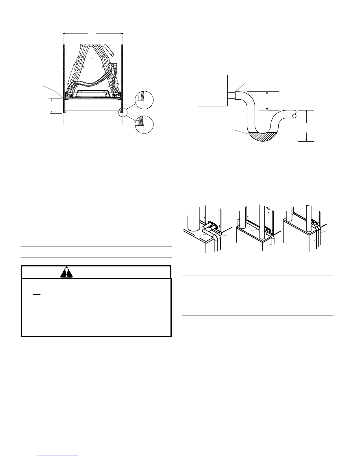
Evaporator Coil Drain Pan Clearances
A
A trap must be installed in the drain line below the bottom of the
drain pan. If a copper drain line is used, solder a short piece of
pipe to the connector before installing a drain fitting.
NOTE: Do not over-torque the ³⁄₄" copper connector to the plastic
drain connection.
When completing the drain line, use a wet rag or heat sink
material on the short piece of pipe to avoid damage to the plastic
drain pan.
F
E
D
B
C
B
A. Coil pan width plus insulation
thickness times 2
B. Bottom flange detail—can be
either
C. Gas furnace
■ If the plenum ductwork is larger than the drain pan in any
D. Field fabricated support for
uncased coil
E. 2" (5.1 cm) from top of furnace to
bottom of coil pan. Must be 6"
(15.2 cm) for oil furnaces.
F. Coil support
direction, the gaps between the drain pan and the plenum
walls must be closed off to avoid bypass of air around the
sides of the drain pan. Use field-fabricated sheet metal
angles wide enough to support the coil where the drain pan is
located and attach them to the inside of the plenum. The
drain pan will rest on the metal angles. If the connection
between the plenum and any duct occurs below the apex of
the coil, seal this seam with sealant.
Install Condensate Drains
Plastic Drain Pan
WARNING
B
A
2" (5.1 cm) Minimum
C
A. Air handler
B. Drain connection
C. Positive liquid seal required at trap
3" (7.6 cm)
Minimum
Typical drain pipe routings to avoid interference with vent piping
are shown in the “Typical Drain Pipe Routing” illustration.
Typical Drain Pipe Routing
80.0%
A
B
A. Secondary drain pipe routing
B. Primary drain pipe routing
A
92.6%
92.6%
B
B
A
Do not use the coil pan that shipped with the unit on
an OIL furnace or any application where the temperature
of the drain pan may exceed 300ºF (149ºC). A high
temperature drain pan (Kit Numbers HTP-A, -B, -C and
-D for nominal widths of 14", 17¹⁄₂", 21" and 24¹⁄₂" [35.6,
44.5, 53.3 and 62.2 cm] respectively) should be used for
this type of application. A field fabricated metal drain
pan can also be used.
The drain pan has a primary and an optional secondary drain with
³⁄₄" NPT female connections. The connectors required can be ³⁄₄"
NPT male PVC or metal pipe and should be hand tightened to a
torque of approximately 37 in/lbs to avoid damage to the drain
pan connection. An insertion depth between 0.355" to 0.485"
(0.9 cm to 1.2 cm) (3 to 5 turns) should be expected at this
torque. If the secondary drain line is required, it must be run
separately from the primary drain and should end where it is
easily seen. Water coming from this line means the coil primary
drain is plugged and needs clearing.
Verify Orifice Size
IMPORTANT: The proper orifice size is dependent on indoor coil/
outdoor unit combination and application. Consult the outdoor
unit information to determine if the indoor unit has the correct
orifice installed.
Connect Refrigerant Lines
Refrigerant lines must be connected by a licensed, EPA certified
refrigerant technician in accordance with established procedures.
IMPORTANT:
■ Connecting refrigerant lines must be clean, dehydrated,
refrigerant-grade copper lines.
■ Evaporator coils should be installed only with specified line
sizes for approved system combinations.
■ Handle the refrigerant lines gently during the installation
process. Sharp bends or possible kinking in the lines will
cause a restriction.
3
Page 4
■ Do not remove the caps from the lines or system connection
W
©
points until connections are ready to be completed.
CAUTION
11. After the tailpiece has cooled, verify the position of the white
®†
seal and hand tighten the nut.
Te fl on
C
To protect the unit when welding close to the painted
surfaces, the use of a quenching cloth is strongly advised
to prevent scorching or marring of the equipment finish.
Solder with a minimum of 5% silver is recommended.
Prepare Tubing
■ All cut ends are to be round, burr free, and cleaned. Failure to
follow this practice increases the chances for refrigerant
leaks.
■ The suction line is spun closed and requires a pipe cutter to
remove the closed end.
Post Brazing
■ Cool all welded joints with water or a wet rag.
Piping Size
For the correct tubing size, follow the specification for the
condenser/heat pump.
WARNING
This product is factory-shipped under pressure. Follow
these instructions to prevent injury.
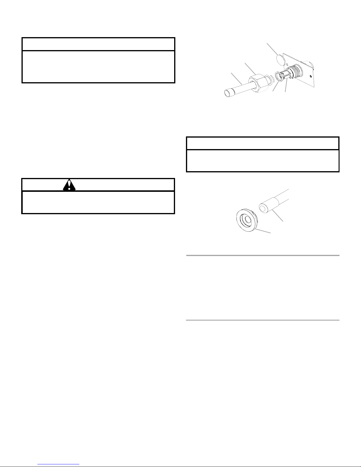
Check Orifice and Connect Tubing
1. Loosen the ¹³⁄₁₆" nut 1 turn only.
NOTE: No pressure loss indicates a possible leak.
2. Remove the nut and discard the plastic or brass cap.
3. Remove the check piston to verify it is correct, and then
replace the piston. See piston kit chart in instructions.
4. Use a tube cutter to remove the spin closure on the suction
line.
5. Remove the tailpiece clamped to the exterior.
6. Slide the ¹³⁄₁₆" nut into position on the tailpiece.
7. Braze the tailpiece to the liquid tube.
8. Insert the suction line into the connection.
9. Slide the insulation and the rubber grommet at least 18"
(45.7 cm) away from the braze joint.
10. Braze the suction line.
B
A
E
D
A. Tailpiece
¹³⁄₁₆
" nut
B.
C. Plastic or brass cap
12. Torqu e th e ¹³⁄₁₆" nut to 20 to 30 ft-lbs. (2.77 to 4.15 m-kg).
D. Piston
E. White Teflon® seal
CAUTION
Excessive torque can cause orifices to stick. Use the
proper torque settings when tightening orifices.
13. Replace the suction line grommet and insulation.
A
B
A. Suction line with spin closure
B. Rubber grommet
ASSISTANCE OR SERVICE
If you need further assistance, you can write to the below
address with any questions or concerns:
Whirlpool
14610 Breakers Drive
Jacksonville, FL 32258
Please include a daytime phone number in your correspondence.
To order accessories contact your Whirlpool® Home Cooling and
Heating dealer.
®
Home Cooling and Heating
Accessories
PIO-284B
2009. All rights reserved.
Manufactured under license by Tradewinds Distributing Company, LLC., Jacksonville, Florida
®Registered Trademark/TM Trademark of Whirlpool, U.S.A.,
†®Teflon is a registered trademark of Dupont.
Printed in U.S.A.
8/09
 Loading...