

Whirlpool WBM35LW, WBM39LW, WBM35LS, WBM39LS, WBM46LW Service Manual
...
WHIRLPOOL CONSUMER SERVICES
Models WBM35LW
WBM35LS
WBM39LW
WBM39LS
WBM46LW
WBM46LS
March 2003
This Service Manual supersedes Service Manual, Part No. SM1100, dated July 02.
Please remove and destroy the superseded manual.
Copyright © 2002 Whirlpool (Australia) Pty. Limited
All rights strictly reserved. Reproduction or issue to third parties in any form whatsoever is not
permitted without written authority of Whirlpool (Australia) Pty. Limited
Whirlpool is a registered trademark of Whirlpool U.S.A.
This documentation is intended only for qualified technicians who possess the required qualifications and are
aware of the regulatory requirements applicable to servicing electrical appliances.
Whirlpool (Australia) Pty Limited Part No. SM1101
A. B. N. 28 003 578 023
WHIRLPOOL AUSTRALASIA
CONSUMER SERVICES
SERVICE MANUAL
ELECTRONIC
TOP MOUNT REFRIGERATOR
Model Version
WMB35LW 8534 772 53000
WBM35LS 8534 772 53010
WMB39LW 8534 773 53000
WBM39LS 8534 773 53010
WMB46LW 8534 774 53000
WBM46LS 8534 774 53010

WHIRLPOOL CONSUMER SERVICES
Models WBM35LW
WBM35LS
WBM39LW
WBM39LS
WBM46LW
WBM46LS
Page 1 of 34
CONTENTS
Page
1. IDENTIFICATION 2
2. TECHNICAL SPECIFICATIONS 3
3. FUNCTIONAL CHARACTERISTICS 3
3.1. Lamp Activation System 3
3.2. Product Electronic Control System 4
3.2.1. Freezer Temperature Control 5
3.2.2. Refrigerator Temperature Control 6
3.2.3. Fan Motor Operation 6
3.2.4. Door Opening Management 6
3.2.5. Freezer Freezing Level Selection 7
3.2.6. Defrost System 7
3.2.6.1. Defrost Problems 8
3.2.7. Alarm System 8
3.2.7.1. 2Hz Alarm 10
3.2.7.2. 4Hz Alarm 12
4. TESTS
4.1. Test Routine on Electronic Board 16
4.2. Self Test General Notes 17
5. OTHER COMPONENTS 17
5.1. Cooling Fluid (Refrigerant) 17
5.2. Cabinet 17
5.3. Compressor 18
5.4. Evaporator and Suction Line 18
5.5. Filter/Dryer 18
5.6. Kickplate 18
5.7. Doors and Gaskets 19
5.8. Clicking Stop Bushing 19
5.9. Rollers and Levelling Feet 20
5.10. Vegetable Crisper Humidity Control 20
5.11. Neutraliser 20
5.12. Clean Back 20
5.13. Can Rack 21
5.14. Capacitor 21
6. COMPONENT ASSEMBLY, DISASSEMBLY AND REPLACEMENT 21
6.1. Disassembling the Evaporator Front and Rear Covers 21
6.2. Replacing the Bimetallic and Thermofuse 22
6.3. Replacing the Defrost Heater 22
6.4. Replacing the Air Diffuser and Damper 22
6.5. Assembling and Disassembling the Refrigerator Internal Components 22
6.6. Replacing the Fan Motor 23
6.7. Replacing the Temperature Sensor 23
6.8. Replacing a Cable Connection for the Potency Module 26
6.9. Replacing Evaporator 26
6.10. Replacing or Removing the Cleanback 27
7. REVERSING DOOR SWING (OPTIONAL) 28
8. REQUIRED TOOLS 31
9. WIRING DIAGRAM 32
10. FAILURE CORRECTION CHART 33

MSEX0025_rev01
2
1 – IDENTIFICATION :
1.1 – Multibras Version
W R M 34 A B Z WL
EX = MARKET: WL = AUSTRALIA
D = VOLTAGE: Z= 220-240/50Hz, D=220/50Hz
B = COLOR B= WHITE, P= SILVER, R= INOX
A = VERSION: A= FIRST, X= INOX VERSION
34 = CAPACITY: 34=340 LITERS,
38=380 LITERS,
44=440 LITERS
M = TYPE: NO FROST
R = PRODUCT: REFRIGERATOR
W = BRAND: WHIRLPOOL
1.2 – Multibras Serial Number
X X X XXXXXX
The first digit indicates the Factory Plant (in Brasil), identified by a letter as follows:
C – Rio Claro Plant P – São Paulo Plant
S – São Bernado Plant J – Joinville Plant
I – Imported Products M – Manaus Plant
The second digit indicates the manufacturing month of the product:
A – January D – April G – July J – October
B – February E – May H – August L – November
C – March F – June I – September M – December
4th to 9th Digit: Serial Number (Sequential)
3rd Digit: Manufacturing Year
2nd Digit: Manufacturing Month
1st Digit: Factory
MSEX0025_rev01
3
The third digit indicates the manufacturing year of the product:
8 – 1998 1 – 2001 4 – 2004 7 – 2007
9 – 1999 2 – 2002 5 – 2005 8 – 2008
0 – 2000 3 – 2003 6 – 2006 9 – 2009
The following six digits indicate the product manufacturing sequential:
Example: 000001, 000002, ..
2 – TECHNICAL SPECIFICATIONS :
Characteristics MODEL WRM34, WBM35 WRM38, WBM39 WRM44, WBM46
VOLTS (V)
220/240 220/240 220/240
FREQUENCY (Hz)
50 50 50
CURRENT ( A )
0,7 0,7 0,7
POWER ( W )
145 145 145
HEATER POWER ( W )
190 225 225
CIRCUIT BREAKER ( A )
10 10 10
POWER CONSUMPTION (Kwh/ year)
571 581 616
REFRIGERANT LOAD
90 95 100
COMPRESSOR MODEL
TPH1380YXC TPH1380YXC TPH1380YXC
(R-134A / TECUMSEH)
TP152JR TP152JR TP152JR
COMPRESSOR POWER (W) or (HP)
196 or 1/4 196 or 1/4 196 or 1/4
3 – FUNCTIONAL CHARACTERISTICS:
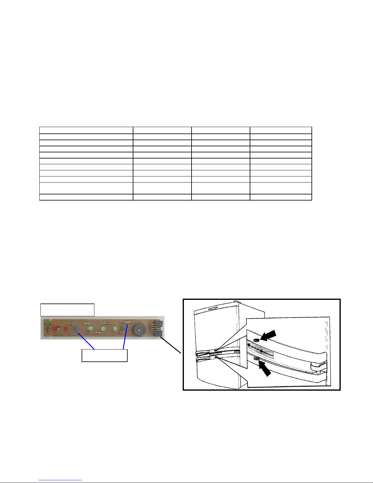
3.1 – Lamp activation system :
The WBM39 and WBM46 models are fitted with 15-watt Lamps, one in the Refrigerator Compartment and
the other in the Freezing Compartment (except for WRM34, WBM35 models). They are activated by means
of two magnets internally, located on the upper portion of the refrigerator door and on the lower portion of
the Freezer door (except for WRM34, WBM35 models), which connect a reed switch existing on the
Interface Board (see drawing below).
Interface Board
Reed Switch
Magnets
MSEX0025_rev01
4
When the door is closed, the magnet is on the Interface Board, which informs the Potency Module causing
the corresponding Lamp to remain OFF. When the door is opened, the magnet stays away from the
Interface Board and the Lamp turns ON. The technician can test the activation system by using a round
magnet with approximately 20 mm in diameter and 5 mm in height (preferably).
The WRM34, WBM35 models are fitted with only one lamp on the Refrigerator Compartment, but their
activation system is the same of the others models
.
3.2 – Product Electronic Control System :
The Refrigerator is fully operated by an Electronic Control System which performs several functions. This
electronic control system consists of the following components:
• Potency Module
• Temperature Sensor
• Interface Board
The following described are the characteristics of each control system component:
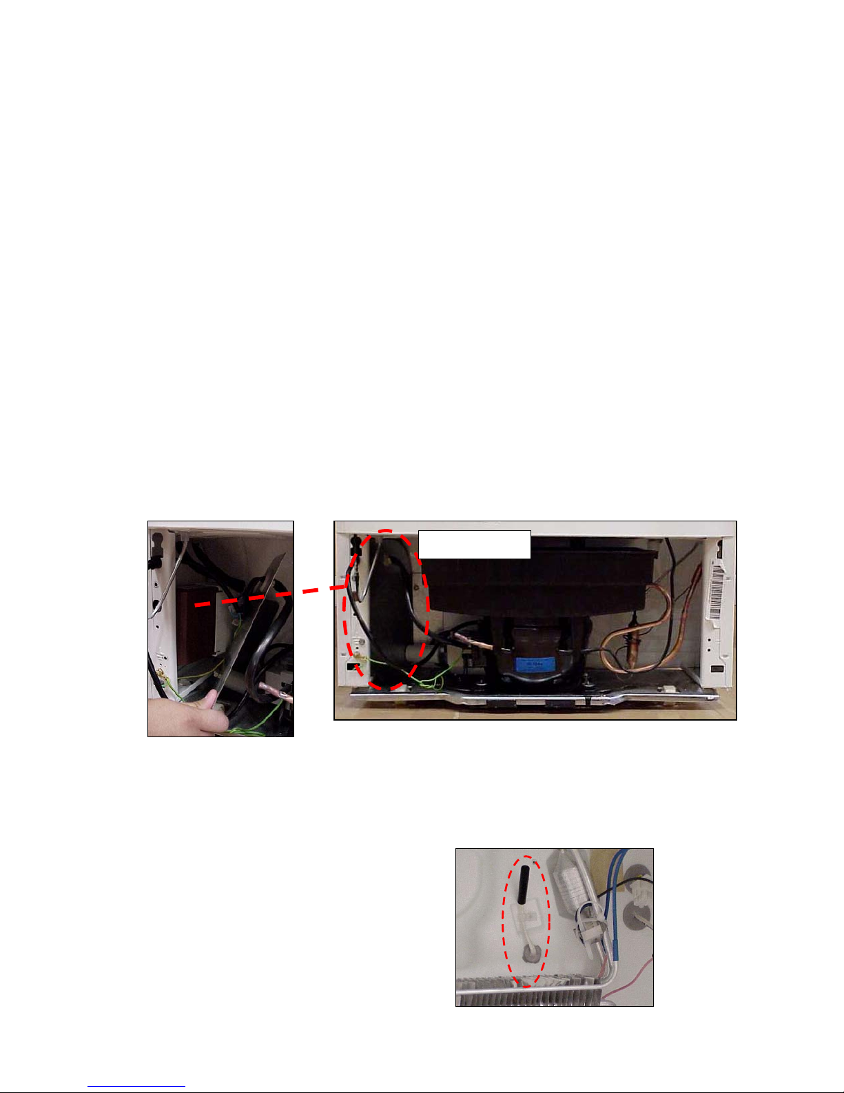
• Potency Module :
Fixed in the Cabinet, located beside the Compressor and behind to the metallic cover. The connection from
the Potency Module to the Electric Line and Power Cable is made via connectors with fault-intolerant
fittings.
The replacement of the connectors connecting to the Module is possible through an adapting process,
avoiding the need for changing the Cabinet or Refrigerator. See how to proceed by referring to Item 6.8 Adapter for connecting to Potency Module.
• Temperature Sensor :
Responsible for monitoring the air temperature on the
Evaporator input, sending signals to the Potency
Module. It is connected to the Potency Module for
Cabinet internal wiring.
Potency Module

MSEX0025_rev01
5
• Interface Board
Responsible for sending signals to the
Potency Module in order to turn the Lamps
and the Fan Motor ON and OFF, with a
Freezer temperature range selection, for
turning the alarm off, Fast Freezing
function, powered-on product signaling,
open door signaling and open door audible
signal. For disassembly or replaced it,
remove the Console Display by forcing it
upward with a medium size screwdriver .
Then pull it forward. Disconnect the
Interface Board from the Flat Cable (multiway cable) and replace it.
REMARKS
• Whenever the Refrigerator is powered on, the red Led with the ON inscription should remain lit.
3.2.1 – Freezer Temperature Control :
The temperature inside the product is dependent on the quantity of stored food and on the door opening
frequency.
The Temperature Sensor is located behind the Evaporator and is responsible for monitoring the Freezer
inner temperature. When the temperature on the Sensor is higher than the selected temperature range (see
table below), the Potency Module will turn the Compressor on. When the Sensor detects a temperature
value lower than that of the selected range, the Potency Module will turn the Compressor off.
The temperatures in the compartments are described as follows:
Freezer Compartment
MODEL ADJUST POSITION SWITCH ON SWITCH OFF
WRM34, WBM35 MINIMUM - 9°C - 18°C
WRM38, WBM39 MEDIUM - 13°C - 21°C
WRM44, WBM46 MAXIMUM - 20°C - 27°C
REMARKS
• The Refrigerator control system is fitted with a time counter which allows the compressor to be turned
on only after elapsing SEVEN minutes from the power down. This prevents the Compressor from
attempting to start while the system pressures are not equalized yet.
Console Display
Interface Board
Flat Cable
MSEX0025_rev01
6
• This temperature value is measured close to the Sensor, not at the Freezer Compartment center
3.2.2 – Refrigerator Temperature Control
The temperatures in the Refrigerator compartment are controlled by a Thermostatic Damper, which controls
the cold air flow with three graduations (minimum, medium and maximum).
The Damper does not activates or sends any signal for the Compressor to be either enabled or disabled.
The Damper works independently from the Compressor, that is, it only opens or closes the passage of cold
air from the Freezer to the Refrigerator, increasing or reducing the air flow, thereby controlling the
temperature in this compartment as per the selected graduation.
The temperatures in the compartments are described as follows:
Refrigerator Compartment
MODEL POINT ADJUST POSITION
MINIMUM MEDIUM MAXIMUM
Cold Room 2 to 4°C -1 to 1°C -4 to –6°C
WRM34, WBM35
WRM38, WBM39 Shelves (Center) 7 to 9°C 4 to 6°C -1 to 1°C
WRM44, WBM46
Vegetable Drawer 13 to 15°C 10 to 12°C 7 to 9°C
3.2.3 – Fan Motor Operation:
The Fan Motor is attached to the Evaporator Rear Cover by a bolt and is responsible for circulating the
forced air inside the Refrigerator.
The Fan Motor:
• Works independently from the Compressor and is managed by the electronic control
• Turns off whenever any of the doors is opened.
3.2.4 – Door Opening Management :
Whenever one of the doors is open, the following takes place:
• The corresponding Lamp turns on.
• The Fan Motor turns off.
• The red Led with the DOOR OPEN inscription becomes on.
• After the door is Open for more than 1 minute and a half, the red LED will start flashing and an alarm
will sound at a frequency of 2 Hz (20 bips at every 10 seconds), warning the consumer. The audible
alarm will be turned off by pressing the ALARM OFF button, but the LED will remain on. After more than
1 minute and a half have elapsed, the alarm will sound again and the LED will flash again. This situation
will be repeated at every 1 minute and half until the Door is closed, when all those functions will then be
turned off.

MSEX0025_rev01
7
• Should the Door remain open for 6 minutes the electronic control system will turn the Lamps off and turn
the Fan Motor on again (if compressor is on). Thence, the Refrigerator starts cycling normally, even with
the Door open. The alarm is however sounding and the DOOR OPEN Led and the green Leds for
temperature selection will flash intermittently until the Door is closed. The audible alarm, however, can
be turned off by pressing the ALARM button.
3.2.5 – Freezer Freezing Level Selection :
For all models, every time the face FREEZING LEVEL button is pressed, the levels MINIMUM, MEDIUM or
MAXIMUM is selected according to the table in item 3.2.1 and the corresponding green Led turns on. If the
consumer does not inform the desired temperature level, the Refrigerator will automatically start on the
Medium level.
If the consumer still pressing the Freezing Level button, the FAST FREEZING function will be activated (at
this moment the three green Led’s are simultaneously lit ), which temporarily eliminates the Temperature
Sensor performance, the Compressor will remain on for up to 18 hours. When the function is enabled, the
electronic control system stops controlling the Compressor and Fan Motor operation.
To disable it, the FREEZING LEVEL button must be pressed again. The product will then operate again on
the last temperature range it was previously selected. In case the function is not disabled, the electronic
control will do it after 18 HOURS.
NOTES
• Should the Door be open when the Fast Freezing function is on, the system performs
its function normally, the fan however should only be turned on after 6 minutes or when
the Door is closed.
• Should the Refrigerator be performing the Defrost operation when the Fast Freezing
function is enabled, the electronic system will complete this and only then the Fast
Freezing will start. The Interface Board, however, remains with the 3 green Leds lit,
indicating to the User that the Fast Freezing function has been enabled.
• Should the Fast Freezing function last for the maximum time (18 hours), the
Refrigerator will perform 2 Defrost operations.
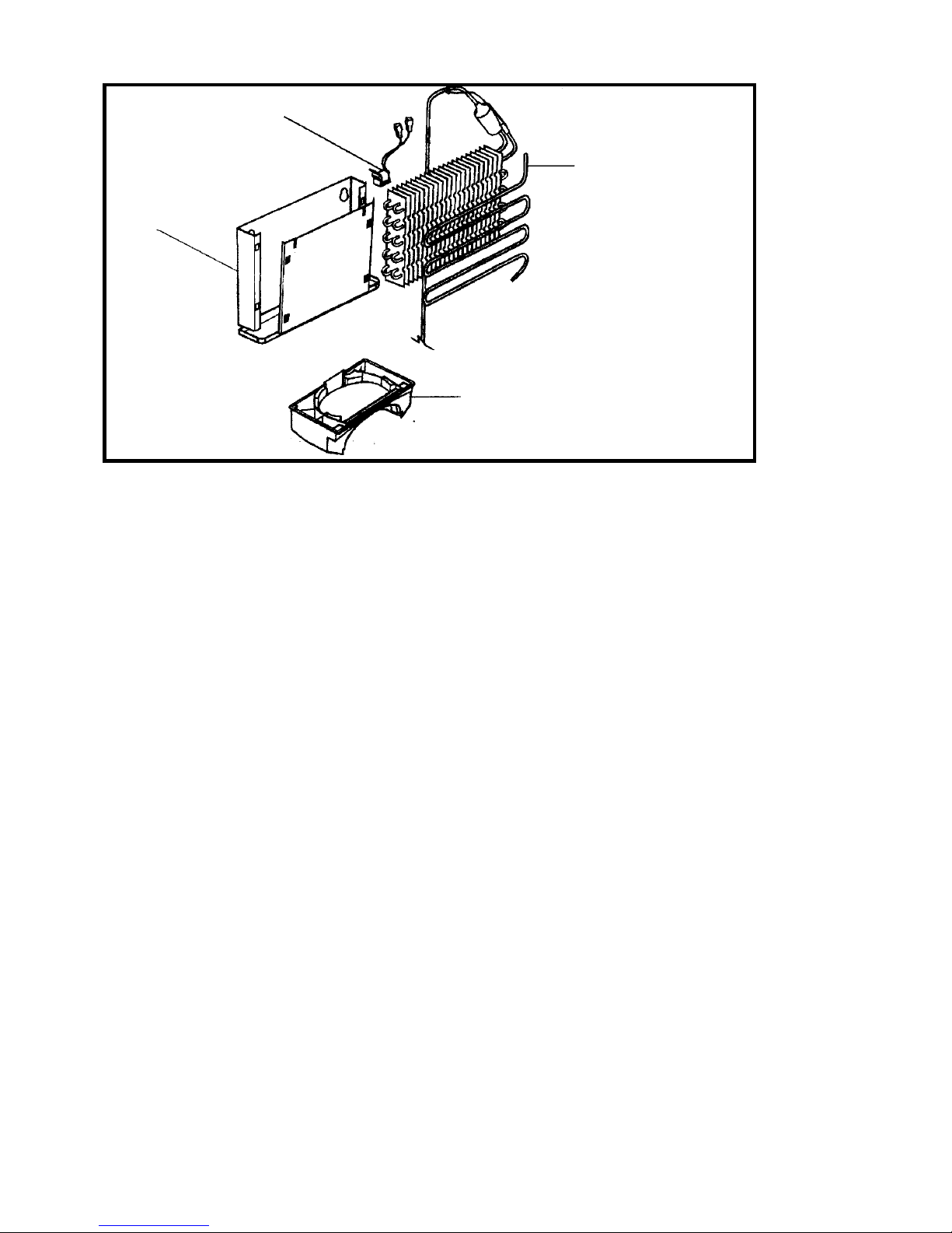
3.2.6 – Defrost System:
See the items making up the Defrost System on the below drawing:
MSEX0025_rev01
8
The Bimetalic (Opening at 15°C and closing at - 6°C) will turn the Defrost Heater off as soon as all ice
existing on the Evaporator has melted. The Defrost Heater, in turn, defrosts the Evaporator more quickly
because it is all along the evaporator length.
The defrost occurs after the Compressor is running for 7 Hours, when it and the Fan Motor are then turned
off and the Heater is turned on. The average Defrost time is 20 to 40 minutes (maximum time).
After the Bimetalic turns the Heater off, it takes 3 minutes for the Compressor to start operating, this time
being enough for all defrosting water to flow out to the Evaporation Container. Once the Compressor is on,
the Fan still awaits another 3 minutes to be in service.
3.2.6.1 – Problems liable to happen during the defrost:
As previously seen the maximum defrost time can not exceed 40 minutes; if this occurs, the electronic
system itself cuts off the Heater current and the defrost is finished. The system however regards this as a
FAULT.
In case this FAULT occurs on 3 consecutive defrosts, the Refrigerator starts to operate normally again,
however all Leds − except for the ON Led − will flash and an alarm will sound at a frequency of 4 Hz (40
bips at every 10 seconds), warning the consumer.
The consumer can disable the alarm by clicking on the ALARM OFF button and should call the Authorized
Service. However, the 3 green Leds will continue to flash. In the event the fault is not yet cleared after 2
Hours, the audible alarm will act again and the customer should disable it again.
This means there is a problem on the defrost components (Heater and/or Bimetal), or on the electronic
control system itself.
Likewise, if the defrost time on three consecutive defrosting lasts less than 8 minutes, the electronic
system will also interpret this as a FAULT and will warn the consumer as described above.
3.2.7 – Alarm System:
These refrigerators have an interface system to the consumer through visual and sound Alarm.
Chute
Defrost Bimetalic & Thermofuse
Defrost Heater
Evaporation Container
MSEX0025_rev01
9
Should the product present any irregularity, it will set off a sound and visual alarm (2 or 4 Hz: see items
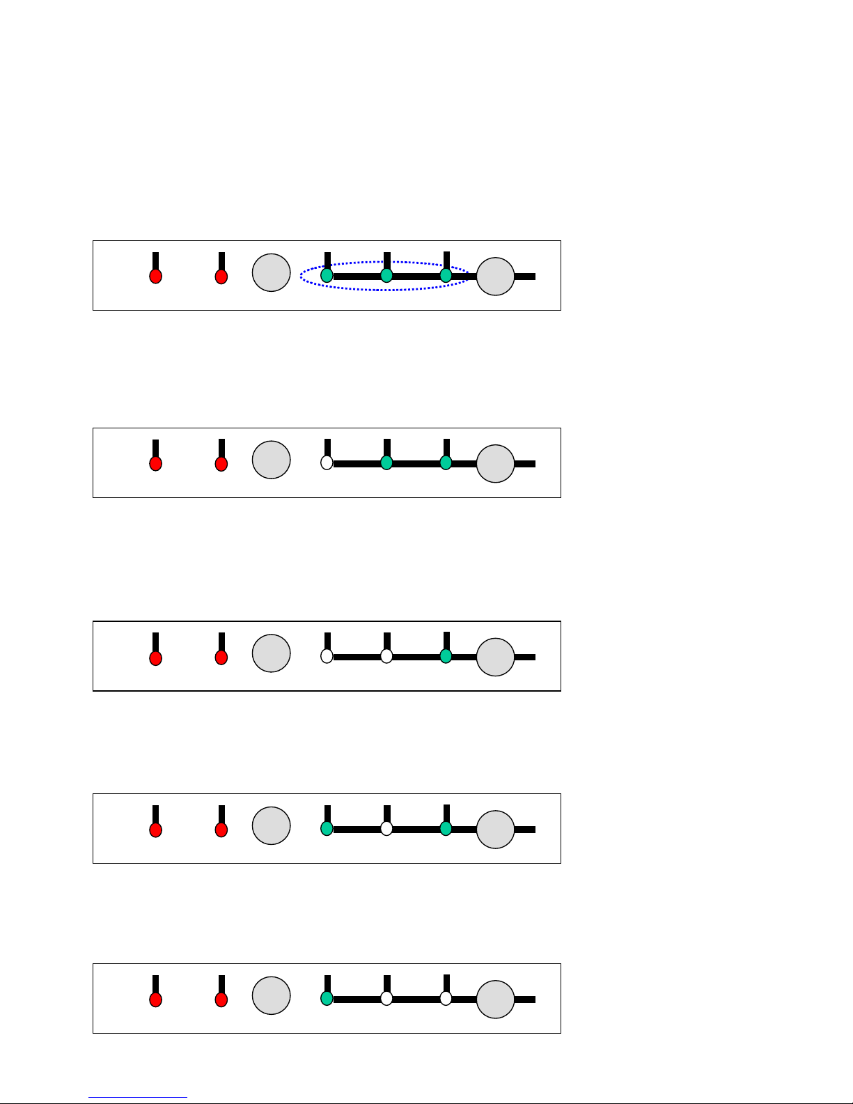
3.2.7.1 and 3.2.7.2, respectively) and a fault code will be stored in the memory of the Interface Board.
Before visiting a client requiring service, we must request that they press the Alarm Off key for a few
seconds and the failure code will appear automatically (combination of the LEDs “Freezing Level “,
Minimum, Medium and Maximum turned on/off as indicated below), providing a pre-diagnosis for the
technician, so that the equipment/pieces necessary to resolve the problem in one visit can be taken. The
codes are:
Code 1 – On / On / On
Fault: Freezer Door open for more than 6 minutes
Solution: Advise the client to close the door; if it continues, follow the instructions in item 3.2.7.1 – 2Hz
Alarm
Code 2 – Off / On / On
Fault: Refrigerator Door open for more than 6 minutes
Solution: Advise the client to close the door; if it continues, follow the instructions in item 3.2.7.1 – 2Hz
Alarm
Code 3 – Off / Off / On
Fault: Freezer Temperature over 0o C
Solution: Technician must visit client and proceed according to the instructions in item 3.2.7.1 – 2Hz Alarm
Code 4 – On / Off / On
Fault: Temperature sensor circuit open
Solution: Technician must visit client and proceed according to the instructions in item 3.2.7.1 – 2Hz Alarm
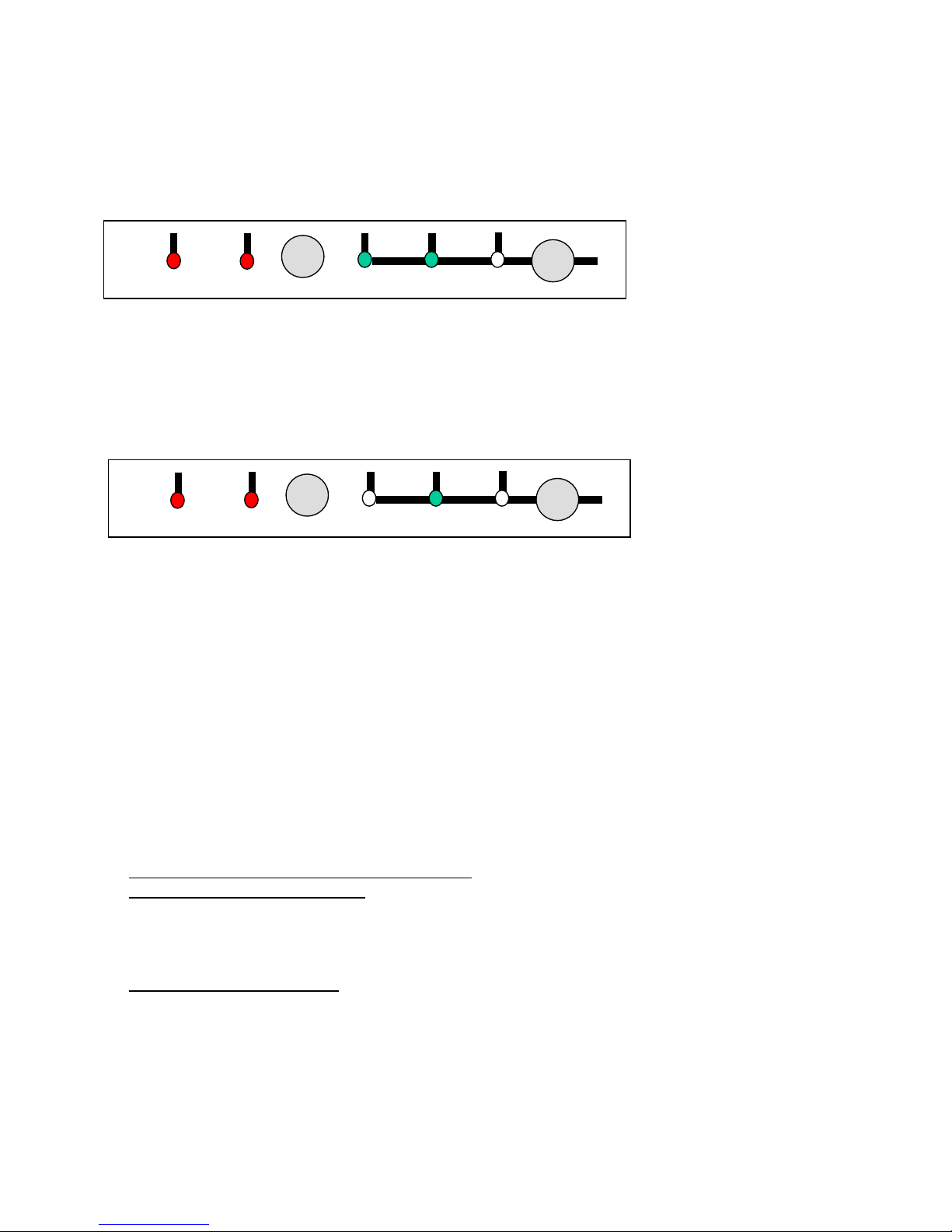
Code 5– On / Off / Off
Medium
Min.
Freezing Level
On
Doo
r
Open
Alarm Off
Máx.
Medium
Min.
Freezing Level
On
Doo
r
Open
Alarm Off
Máx.
Medium
Min.
Freezing Level
On
Door
Open
Alarm Off
Máx.
Medium
Min.
Freezing Level
On
Door
Open
Alarm Off
Máx.
Medium
Min.
Freezing Level
On
Doo
r
Open
Alarm Off
Máx.
MSEX0025_rev01
10
Fault: Bimetal does not open for 3 consecutive defrost cycles
Solution: Technician must visit client and proceed according to the instructions in item 3.2.7.2 – 4Hz Alarm
Code 6– On / On / Off
Fault: Bimetal opens when not defrosting
Solution: Technician must visit client and proceed according to the instructions in item 3.2.7.2 – 4Hz Alarm
Code 7– Off / On / Off
Fault: Bimetal opens too quickly for 3 consecutive defrost cycles
Solution: Technician must visit client and proceed according to the instructions in item 3.2.7.2 – 4Hz Alarm
When one of these faults occur, the client must be instructed to turn off the sound alarm by
pressing the Alarm Off key, however, THE PRODUCT MUST NOT BE UNPLUGGED FROM THE WALL
SOCKET.
As previously mentioned, these faults are related to the 2 or 4Hz Alarms, and are explained in greater detail
as follows:
3.2.7.1 - 2Hz Alarm
This type of alarm is identified through interface Board LEDs that blink 20 times each 10 seconds, together
with sound Beeps, being associated with:
• Door Opened for more than one and half minute: (See Item 3.2.4 Door Management)
• Lack of Magnet inside the Door: these models have an injected Magnet (foamed) together with the
Doors (next to the Upper and Lower Heads) as shown in item 3.1, Lights Actuation System; so, if the
magnet is missing, the product would assume that the door is open and it would actuate the 2 Hz alarm
system; therefore, aided by another magnet, check if the magnet exists by passing it over the plastic
Heads. If magnetic attraction exists, discard this possibility.
• Temperature Sensor Failure, which is reading temperatures above zero at the Freezer, while the
product is normally working (cooling) at a temperature below zero. This type of failure is most likely to
happen during night/dawn hours when the Doors opening is less frequent.
Sensor Analysis Procedure
Medium
Min.
Freezing Level
On
Doo
r
Open
Alarm Off
Máx.
Medium
Min.
Freezing Level
On
Doo
r
Open
Alarm Off
Máx.
 Loading...