

Whirlpool W5WCE065XW0, W7WCC065XB0, W5WCE128XW0, W5WCE085XW0, W5WCE105XW0 Technical Education
Technical Educaon
2011 Room Air Condioners
R-113
Prepared by: WHIRLPOOL CONSUMER CARE
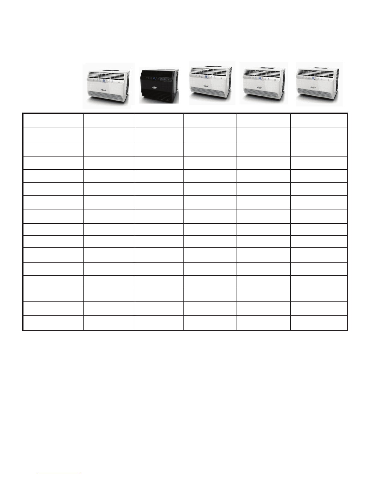
Models
W5WCE065XW0
W7WCC065XB0
W5WCE085XW0
W5WCE105XW0
W5WCE128XW0
Job Aid W10411218
i

FORWARD
This Room Air Condioner Guide (W10411218), provides the In-Home Service Professional with informaon on how to access the controls, motors and fans on Whirlpool’s 2011 room air condioners.
For specic informaon on the model being serviced, refer to the informaon supplied with the air condioner. Always use the Tech Sheet supplied with the product when servicing.
GOALS AND OBJECTIVES
The goal of this Job Aid is to provide informaon that will enable the In-Home Service Professional to
properly gain access to the controls, motors and fans.
The objecves of this Job Aid are to:
• Understand and follow proper safety precauons.
• Successfully access control or motor components that require repair or replacement.
• Successfully return the air condioner to its proper operaonal status.
WHIRLPOOL CORPORATION assumes no responsibility for any repairs made on our products by anyone other
than authorized In-Home Service Professionals.
®Registered trademark of Whirlpool, U.S.A., KitchenAid, U.S.A., Jenn-Air, U.S.A., or Maytag Corporation or its related companies.
®MAGIC CHEF is a registered trademark of CNA International, used under license.
© 2011 All rights reserved.
i

CONTENTS
Page
GOALS AND OBJECTIVES . . . . . . . . . . . . . . . . . . . . . . . . . . . . . . . . . . . . . . . . . . . . . . . . . . . . . . . . . . . . . . . . .i
SAFETY FIRST . . . . . . . . . . . . . . . . . . . . . . . . . . . . . . . . . . . . . . . . . . . . . . . . . . . . . . . . . . . . . . . . . . . . . . . . . .iv
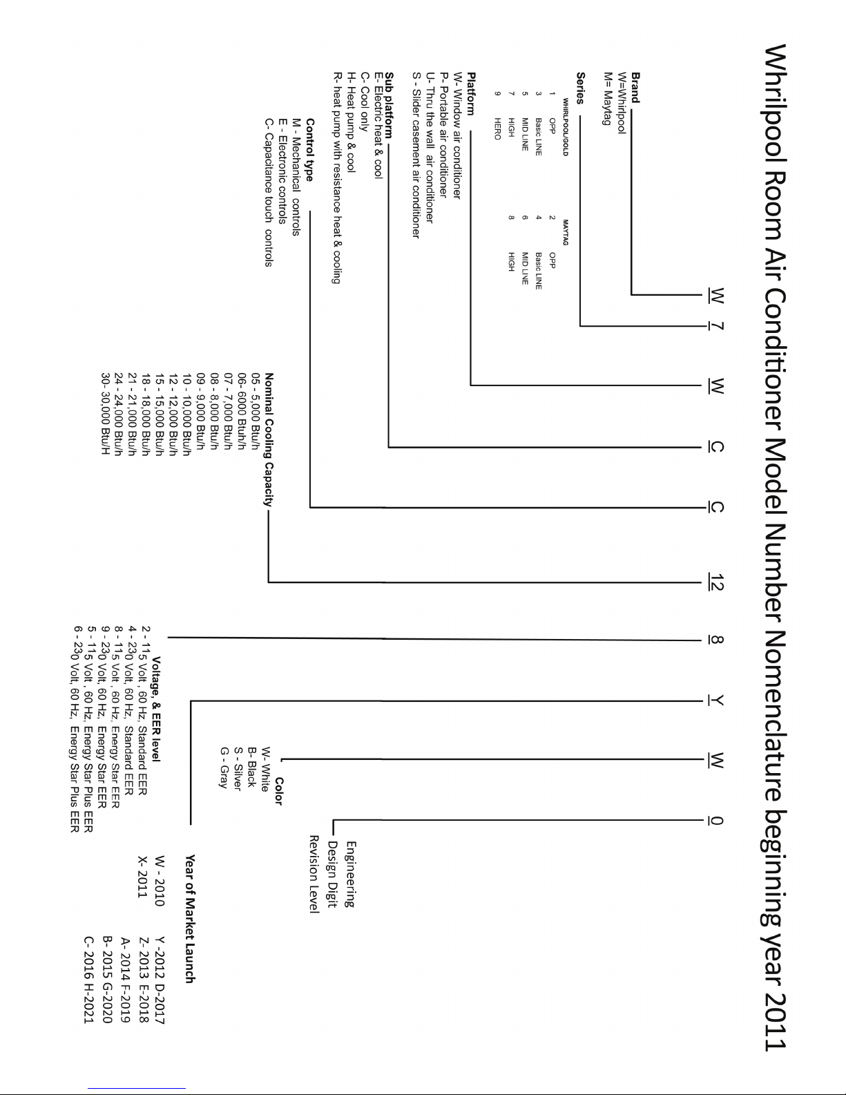
WHIRLPOOL ROOM AIR MODELS NUMBER NOMENCLATURE 2011 ........................... 1-1
SPECIFICATIONS ...................................................................... 1-2
INSTALLATION INFORMATION . . . . . . . . . . . . . . . . . . . . . . . . . . . . . . . . . . . . . . . . . . . . . . . . . . . . . . . . . . 2-1
Window installation . . . . . . . . . . . . . . . . . . . . . . . . . . . . . . . . . . . . . . . . . . . . . . . . . . . . . . . . . . . . . . . 2-1
Location Requirements—All Models . . . . . . . . . . . . . . . . . . . . . . . . . . . . . . . . . . . . . . . . . . . . . . . . . . 2-1
Electrical Requirements . . . . . . . . . . . . . . . . . . . . . . . . . . . . . . . . . . . . . . . . . . . . . . . . . . . . . . . . . . . . 2-2
Recommended Grounding Method ................................................... 2-2
Power Supply Cord . . . . . . . . . . . . . . . . . . . . . . . . . . . . . . . . . . . . . . . . . . . . . . . . . . . . . . . . . . . . . . . . 2-3
Prepare Air Conditioner for Installation ................................................ 2-4
Prepare Window for Installation . . . . . . . . . . . . . . . . . . . . . . . . . . . . . . . . . . . . . . . . . . . . . . . . . . . . . 2-4
Complete Installation . . . . . . . . . . . . . . . . . . . . . . . . . . . . . . . . . . . . . . . . . . . . . . . . . . . . . . . . . . . . . . 2-5
PRODUCT OPERATION ................................................................ 3-1
Air Conditioner Safety .............................................................. 3-1
Product Registration . . . . . . . . . . . . . . . . . . . . . . . . . . . . . . . . . . . . . . . . . . . . . . . . . . . . . . . . . . . . . . . 3-1
Starting Your Air Conditioner . . . . . . . . . . . . . . . . . . . . . . . . . . . . . . . . . . . . . . . . . . . . . . . . . . . . . . . . 3-2
Mode . . . . . . . . . . . . . . . . . . . . . . . . . . . . . . . . . . . . . . . . . . . . . . . . . . . . . . . . . . . . . . . . . . . . . . . . . . . 3-3
Fan Speed ........................................................................ 3-4
Temperature . . . . . . . . . . . . . . . . . . . . . . . . . . . . . . . . . . . . . . . . . . . . . . . . . . . . . . . . . . . . . . . . . . . . . 3-4
Set Clock ......................................................................... 3-4
Timed On Off . . . . . . . . . . . . . . . . . . . . . . . . . . . . . . . . . . . . . . . . . . . . . . . . . . . . . . . . . . . . . . . . . . . . . 3-5
Timed Off ........................................................................ 3-5
Timed On . . . . . . . . . . . . . . . . . . . . . . . . . . . . . . . . . . . . . . . . . . . . . . . . . . . . . . . . . . . . . . . . . . . . . . . . 3-5
Timed On and Timed Off ............................................................ 3-5
Cancel All Programming in Timed On Off function ....................................... 3-5
Using the Remote Control. . . . . . . . . . . . . . . . . . . . . . . . . . . . . . . . . . . . . . . . . . . . . . . . . . . . . . . . . . . 3-6
Power . . . . . . . . . . . . . . . . . . . . . . . . . . . . . . . . . . . . . . . . . . . . . . . . . . . . . . . . . . . . . . . . . . . . . . . . . . . 3-6
Mode . . . . . . . . . . . . . . . . . . . . . . . . . . . . . . . . . . . . . . . . . . . . . . . . . . . . . . . . . . . . . . . . . . . . . . . . . . . 3-6
TM
6th Sense
Storing the Remote Control . . . . . . . . . . . . . . . . . . . . . . . . . . . . . . . . . . . . . . . . . . . . . . . . . . . . . . . . . 3-7
Fan Speed ........................................................................ 3-7
Temperature . . . . . . . . . . . . . . . . . . . . . . . . . . . . . . . . . . . . . . . . . . . . . . . . . . . . . . . . . . . . . . . . . . . . . 3-7
Changing Air Direction . . . . . . . . . . . . . . . . . . . . . . . . . . . . . . . . . . . . . . . . . . . . . . . . . . . . . . . . . . . . . 3-7
Air Conditioner Care . . . . . . . . . . . . . . . . . . . . . . . . . . . . . . . . . . . . . . . . . . . . . . . . . . . . . . . . . . . . . . . 3-8
Cleaning the Air Filter . . . . . . . . . . . . . . . . . . . . . . . . . . . . . . . . . . . . . . . . . . . . . . . . . . . . . . . . . . . . . . 3-8
Cleaning the Front Panel ............................................................ 3-8
Repairing Paint Damage . . . . . . . . . . . . . . . . . . . . . . . . . . . . . . . . . . . . . . . . . . . . . . . . . . . . . . . . . . . . 3-8
Annual Maintenance ............................................................... 3-8
System Control (Only on certain models) ................................... 3-7
COMPONENT ACCESS ................................................................. 4-1
Component Locations .............................................................. 4-1
Removing the Front Panel ........................................................... 4-2
Removing the Cabinet .............................................................. 4-3
Removing the Control and User Interface .............................................. 4-4
Removing the Fan Assembly ......................................................... 4-5
ii

CONTENTS (connued)
Page
DIAGNOSTICS AND TROUBLESHOOTING . . . . . . . . . . . . . . . . . . . . . . . . . . . . . . . . . . . . . . . . . . . . . . . . . 5-1
Voltage Measurement Safety Information . . . . . . . . . . . . . . . . . . . . . . . . . . . . . . . . . . . . . . . . . . . . . 5-1
Electrostatic Discharge (ESD) Sensitive Electronics ....................................... 5-1
Troubleshooting Charts ..........................................................5-2, 5-5
WIRING DIAGRAMS . . . . . . . . . . . . . . . . . . . . . . . . . . . . . . . . . . . . . . . . . . . . . . . . . . . . . . . . . . . . . . . . . . 6-1
Refrigerant System . . . . . . . . . . . . . . . . . . . . . . . . . . . . . . . . . . . . . . . . . . . . . . . . . . . . . . . . . . . . . . . . 6-1
Schematic Diagram . . . . . . . . . . . . . . . . . . . . . . . . . . . . . . . . . . . . . . . . . . . . . . . . . . . . . . . . . . . . . . . . 6-2
iii
SAFETY FIRST
NOTICE TO THE TECHNICIAN
It is the responsibility of the Service Technician to comply with all EPA Regulaons and Standards and
possesses all necessary State and Federal licenses when servicing air condioners.
Federal regulaons and Standards can be found on the United States Government EPA Web Site.
State Regulaons and Standards and licensing requirements, in most cases, can be found on the State
Government Web Site.
iv
11-
Specicaons
W5WCE065XW0 W7WCC065XB0 W5WCE085XW0 W5WCE105XW0 W5WCE128XW0
BTU Rang
6300 6300 8000 10000 12000
EER
11 11 10.9 11 10.7
Voltage
115 VAC 115 VAC 115 VAC 115 VAC 115 VAC
Frequency
60 HZ 60 HZ 60 HZ 60 HZ 60 HZ
Rated Current
7.1 A 7.1 A 9.7 A 10.8 A 12.8 A
Waage
570 W 570 W 730 W 910 W 1110 W
Compressor Type
Rotary Rotary Rotary Rotary Rotary
Compressor LRA
28 A 28 A 32 A 41 A 50.5 A
Compressor AMP
5.3 A 5.3 A 6.75 A 7.8 A 9.50 A
Fan Speed RPM
1100/970/850 1100/970/850 1280/1160/1040 1350/1250/1150 1350/1250/1150
Fan Capacitor MFD
6 uf 6 uf 15 uf 15 uf 15 uf
Refrigerant Type
R410A R410A R410A R410A R410A
Refrigerant Charge
12.3 OZ 12.3 OZ 14.8 OZ 23.2 OZ 24.6 OZ
Weight
44 LB 44 LB 48.5 LB 70.5 LB 70.5 LB
Dimension - mm
480X321X414 480X321X414 480X321X414 480/440/400 503X403X564
All Models use R-410A refrigerant. R-410A operates at higher pressures and temperatures than R-22 units
and requires dedicated sealed system equipment.
Note: Do not aempt sealed system entry or service unless you have been trained on servicing R410-A
systems and have the proper equipment.
1-
2
Installation Information
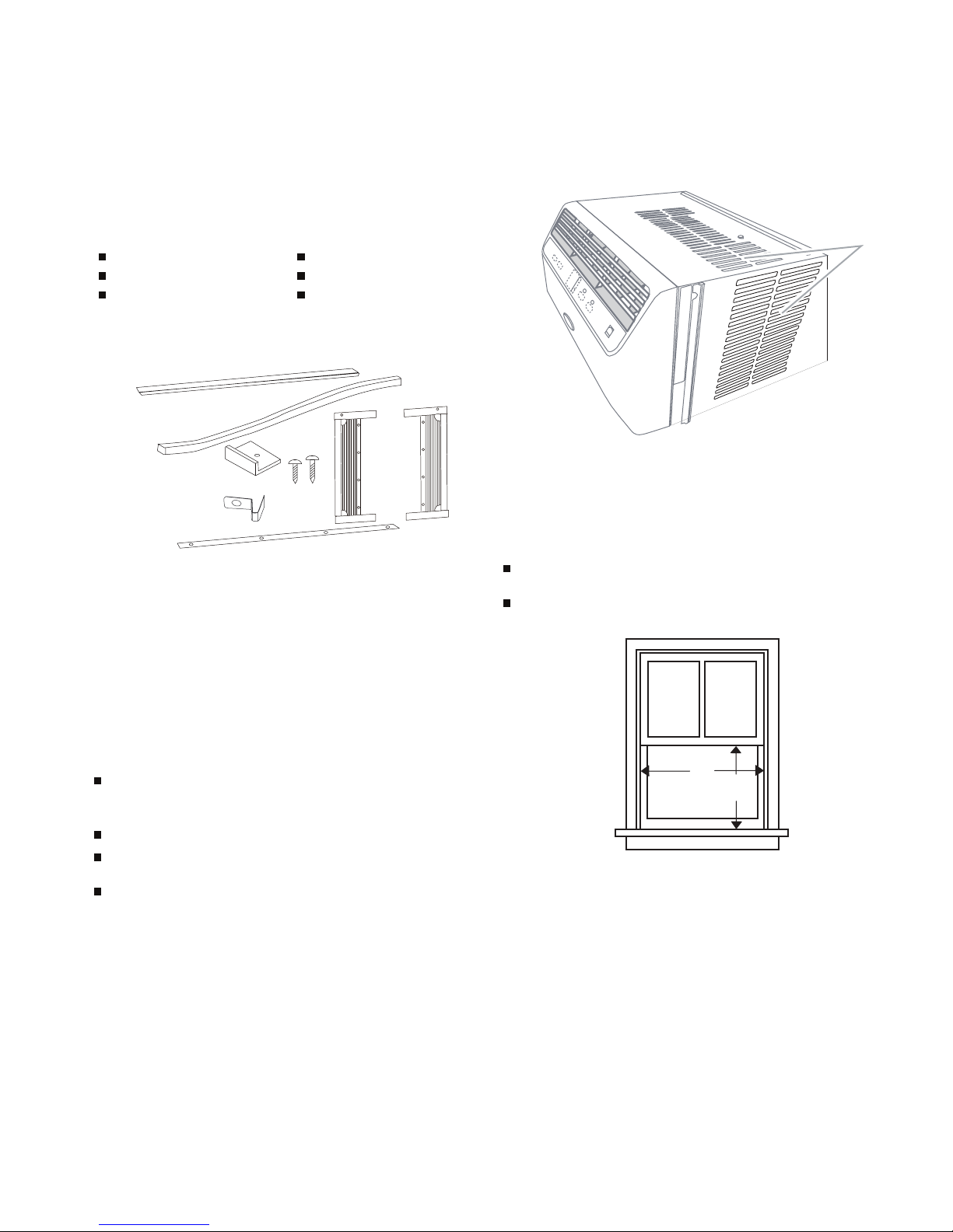
To ols and Pa rts—All Models
Gather the required tools and parts before starng installaon.
Read and follow the instrucons provided with any tools listed
here.
To o ls needed
Parts supplied
Check that all parts are included in parts package.
Locaon Requirements—All Models
IMPORTANT: Observe all governing codes and ordinances.
Check the locaon where the air condioner will be installed.
Make sure you have everything necessary for correct installaon.
The locaon should provide:
Grounded electrical outlet within 6 (183 cm) of where the
power cord exits the air condioner.
NOTE: Do not use an extension cord.
Free movement of air in room to be cooled.
NOTE: Cabinet louvers must not be obstructed. Air must be able
to pass freely through the cabinet louvers.
Window installaon
Window opening measurements:
21" (53.3 cm) minimum to 36 1/2" (85cm) maximum opening
width.
13
1/2" (34.3 cm) minimum opening height.
Phillips screwdriver
Scissors
Level
Tape measure
Cordless drill and 1/8" bit
Pencil
A. Foam seal with
adhesive strip
B. Foam seal without
adhesive strip
C. Window lock
bracket
D. Side bracket
(on some
models)
E. 3/4" screws (4)
(5k, 6k and 8k
models only)
F. 3/4" screws (5)
(6 provided on 10k
and 12k models)
G. Side curtains (2)
H. To p channel seal
(on some models)
A
B
C
D
EF
G
H
A. Cabinet louvers
A
A
B
333/4
NOTE: Cabinet louvers must not be obstructed. Air must be able
to pass freely through the cabinet louvers.
Window installaon
Window opening measurements:
21" (53.3 cm) minimum to 36 1/2" (85cm) maximum opening
width.
131/2" (34.3 cm) minimum opening height.
A. Cabinet louvers
A.21" (53.3 cm) minimum
B.13
1/2" (34.3 cm) minimum
A
A
B
333/4
To ols and Pa rts—All Models
Gather the required tools and parts before starng installaon.
Read and follow the instrucons provided with any tools listed
here.
To o ls needed
Parts supplied
Check that all parts are included in parts package.
Locaon Requirements—All Models
IMPORTANT: Observe all governing codes and ordinances.
Check the locaon where the air condioner will be installed.
Make sure you have everything necessary for correct installaon.
The locaon should provide:
Grounded electrical outlet within 6 (183 cm) of where the
power cord exits the air condioner.
NOTE: Do not use an extension cord.
Free movement of air in room to be cooled.
A large enough opening for the air condioner. Installaon
parts are supplied for double-hung windows.
Adequate wall support for weight of air condioner. Air
condioner weighs 50 lbs to 75 lbs (22.7 kg to 34 kg).
NOTE: Cabinet louvers must not be obstructed. Air must be able
to pass freely through the cabinet louvers.
Window installaon
Window opening measurements:
21" (53.3 cm) minimum to 36 1/2" (85cm) maximum opening
width.
13
1/2" (34.3 cm) minimum opening height.
Phillips screwdriver
Scissors
Level
Tape measure
Cordless drill and 1/8" bit
Pencil
A. Foam seal with
adhesive strip
B. Foam seal without
adhesive strip
C. Window lock
bracket
D. Side bracket
(on some
models)
E. 3/4" screws (4)
(5k, 6k and 8k
models only)
F. 3/4" screws (5)
(6 provided on 10k
and 12k models)
G. Side curtains (2)
H. To p channel seal
(on some models)
A
B
C
D
EF
G
H
A. Cabinet louvers
A.21" (53.3 cm) minimum
B.13
1/2" (34.3 cm) minimum
A
A
B
333/4
2-1
Copies of the standards listed may be obtained from:
Naonal Fire Protecon Associaon
1 Baerymarch Park
Quincy, MA 02269
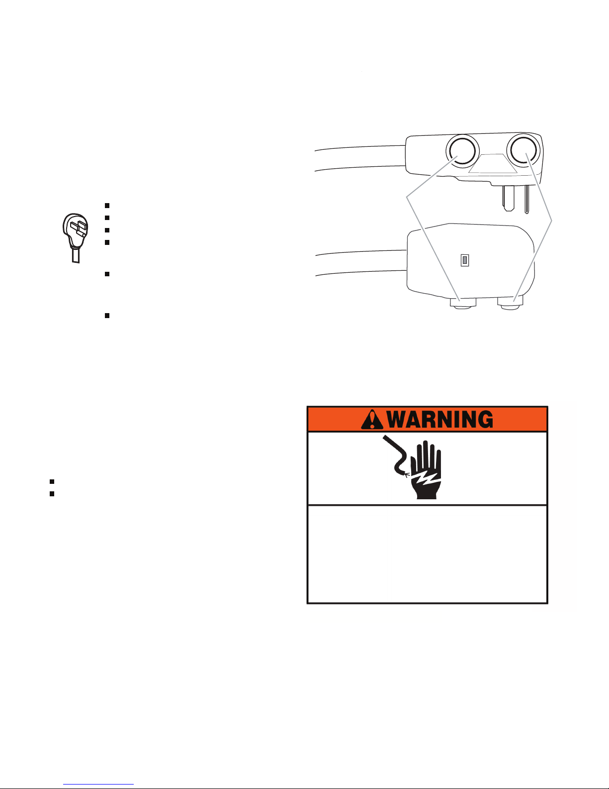
Power Supply Cord
NOTE: Yo ur air condioner’s device may differ from the one
shown.
This room air condioner is equipped with a power supply cord
required by UL. This power supply cord contains state-of-the-art
electronics that sense leakage current. If the cord is crushed, the
electronics detect leakage current and power will be
disconnected in a fracon of a second.
To test your power supply cord:
1. Plug power supply cord into a grounded 3 prong outlet.
2. Press RESET (on some devices, a green light will turn on).
3. Press TEST (listen for click; Reset buon will trip, and on
some devices, a green light will turn off).
4. Press and release RESET (listen for click; Reset buon will
latch, and on some devices, a green light will turn on). The
power supply cord is ready for operaon.
A . Test buon
B. Reset buon
POWER
TEST
RESET
A
B
Electrical Shock Hazard
Plug into a grounded 3 prong outlet.
Do not remove ground prong.
Do not use an adapter.
Do not use an extension cord.
Failure to follow these instrucons can result in death,
fire, or electrical shock.
WARNING
Electrical Requirements—All Models
The electrical rangs for your air condioner are listed on the
model and serial number label. The model and serial number
label is located on the right-hand side of the air condioner
cabinet.
Specific electrical requirements are listed in the “Power Supply
Cord Electrical Requirements” chart. Follow the requirements for
the type of plug shown in the chart.
Recommended Grounding Method
This air condioner must be grounded. This air condioner is
equipped with a power supply cord having a grounded 3 prong
plug. To mi nimize possible shock hazard, the cord must be
plugged into a mang, grounded 3 prong outlet, grounded in
accordance with all local codes and ordinances. If a mang outlet
is not available, it is the customer's responsibility to have a
properly grounded 3 prong outlet installed by a qu alified electrical
installer.
It is the customer's responsibility:
To contact a qualified electrical installer.
To assure that the electrical installaon is adequate and in
conformance with Naonal Electrical Code, ANSI/NFPA
70-latest edion, and all local codes and ordinances.
Copies of the standards listed may be obtained from:
Naonal Fire Protecon Associaon
1 Baerymarch Park
Quincy, MA 02269
Power Supply Cord
NOTE: Yo ur air condioner’s device may differ from the one
shown.
This room air condioner is equipped with a power supply cord
required by UL. This power supply cord contains state-of-the-art
electronics that sense leakage current. If the cord is crushed, the
electronics detect leakage current and power will be
disconnected in a fracon of a second.
To test your power supply cord:
1. Plug power supply cord into a grounded 3 prong outlet.
2. Press RESET (on some devices, a green light will turn on).
3. Press TEST (listen for click; Reset buon will trip, and on
some devices, a green light will turn off).
4. Press and release RESET (listen for click; Reset buon will
latch, and on some devices, a green light will turn on). The
power supply cord is ready for operaon.
Power
Supply
Cord Electrical Requirements
115-volt (103.5 min. - 126.5 max.)
0-12 amps
15-amp me-delay fuse or circuit breaker
If there is a “Single Circuit Only” label on the
unit, use on a dedicated single-outlet circuit
only.
If a dedicated single-outlet circuit is not
available, then it is the customer’s
responsibility to have a single-outlet ci rcuit
installed by a qualified electrician.
If there is no “Single Circuit Only” label on the
unit, the unit may be used on any branch
circuit of correct voltage and adequate current
protecon rang.
Electrical Shock Hazard
Plug into a grounded 3 prong outlet.
Do not remove ground prong.
Do not use an adapter.
Do not use an extension cord.
Failure to follow these instrucons can result in death,
fire, or electrical shock.
WARNING
A . Test buon
B. Reset buon
POWER
TEST
RESET
A
B
Electrical Shock Hazard
Plug into a grounded 3 prong outlet.
Do not remove ground prong.
Do not use an adapter.
Do not use an extension cord.
Failure to follow these instrucons can result in death,
fire, or electrical shock.
WARNING
Electrical Requirements (All Models)
Electrical Shock Hazard
Plug into a grounded 3 prong outlet.
Do not remove ground prong.
Do not use an adapter.
Do not use an extention cord.
Failure to follow these instructions can
result in death, fire, or electrical shock.
To test your power supply cord:
2-2
Installation Requirements (continued)
NOTES:
The Reset buon must be pushed in for proper operaon.
The power supply cord must be replaced if it fails to trip when
the test buon is pressed or fails to reset.
Do not use the power supply cord as an off/on switch. The
power supply cord is designed as a protecve device.
A damaged power supply cord must be replaced with a new
power supply cord obtained from the product manufacturer
and must not be repaired.
The power supply cord contains no user serviceable parts.
Opening the tamper-resistant case voids all warranty and
performance claims.
Cut the 2 plasc bands that secure the carton.
A. " screws
B.Top channel
3/8
Install Side Curtains
NOTE: Aach curtains to the air condioner before placing the air
condioner in window.
1. Place the tabbed side of the side curtain in the track on the
right-hand side of the air condioner cabinet.
2. Slide the side curtain down the track unl the curtain is
aligned with the top and boom of the air condioner cabinet.
A. Tabbed side of side curtain
B. Curtain frame
A
B
A. " screws
B.Top channel
3/8
NOTES:
The Reset buon must be pushed in for proper operaon.
The power supply cord must be replaced if it fails to trip when
the test buon is pressed or fails to reset.
Do not use the power supply cord as an off/on switch. The
power supply cord is designed as a protecve device.
A damaged power supply cord must be replaced with a new
power supply cord obtained from the product manufacturer
and must not be repaired.
The power supply cord contains no user serviceable parts.
Opening the tamper-resistant case voids all warranty and
performance claims.
Cut the 2 plasc bands that secure the carton.
Remove the carton top and li the air condioner from the
base pad.
Remove tape and glue residue fr om surfaces be fore turning
on the air condioner. Rub a small amount of liquid dish soap
over the adhesive wi th your fingers. Wipe with warm water
and dry.
Do not use sharp instruments, rubbing alcohol, flammable
fluids, or abrasive cleaners to remove tape or glue. These
products can damage the surface of your air condioner.
Remove any packaging materials inserted into the side
louvers.
Dispose of/recycle packaging materials.
Install Side Curtains
NOTE: Aach curtains to the air condioner before placing the air
condioner in window.
1. Place the tabbed side of the side curtain in the track on the
right-hand side of the air condioner cabinet.
A
A. " screws
B.Top channel
3/8
NOTES:
The Reset buon must be pushed in for proper operaon.
The power supply cord must be replaced if it fails to trip when
the test buon is pressed or fails to reset.
Do not use the power supply cord as an off/on switch. The
power supply cord is designed as a protecve device.
A damaged power supply cord must be replaced with a new
power supply cord obtained from the product manufacturer
and must not be repaired.
The power supply cord contains no user serviceable parts.
Opening the tamper-resistant case voids all warranty and
performance claims.
INSTALLATION INSTRUCTIONS
Unpack the
Air Condioner
Remove Packaging Materials
Handle the air condioner gently while unpacking the unit.
Cut the 2 plasc bands that secure the carton.
Remove the carton top and li the air condioner from the
base pad.
Remove tape and glue residue fr om surfaces be fore turning
on the air condioner. Rub a small amount of liquid dish soap
over the adhesive wi th your fingers. Wipe with warm water
and dry.
Do not use sharp instruments, rubbing alcohol, flammable
fluids, or abrasive cleaners to remove tape or glue. These
products can damage the surface of your air condioner.
Remove any packaging materials inserted into the side
louvers.
Dispose of/recycle packaging materials.
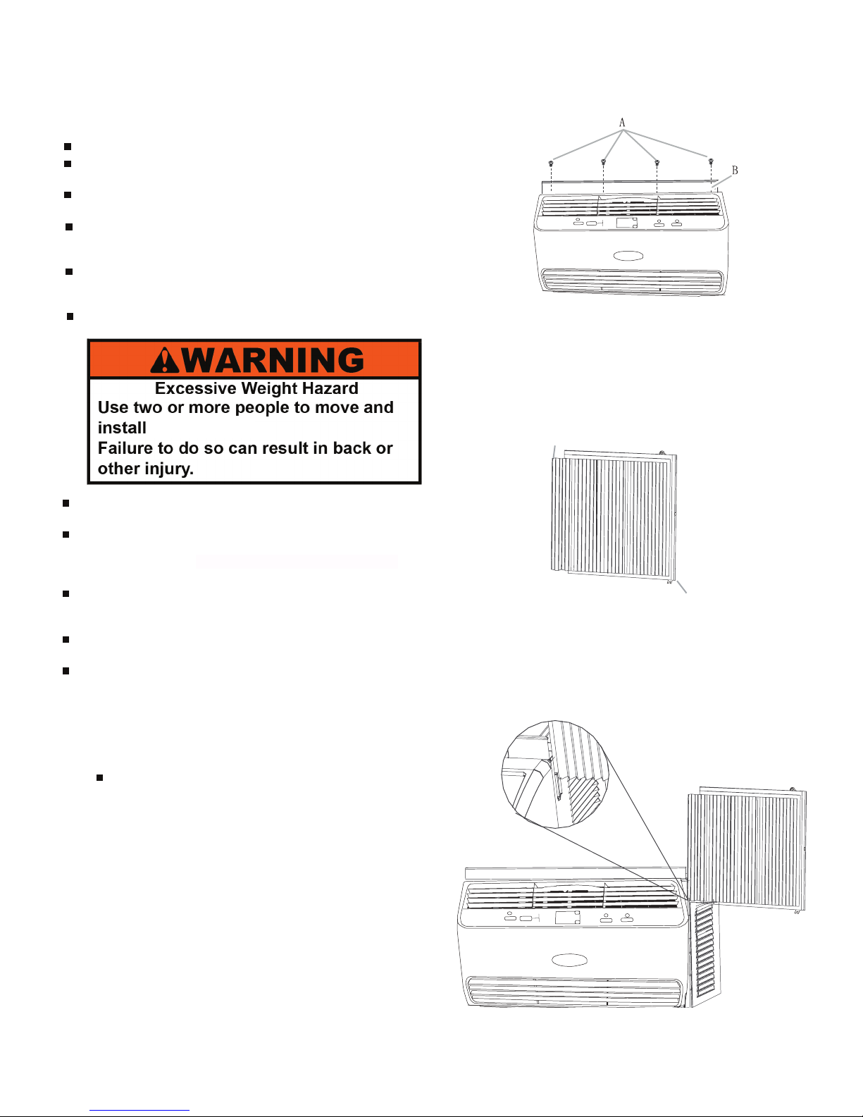
Prepare Air Condioner for Installaon
Install Side Curtains
Install Top Channel
NOTE: Aach curtains to the air condioner before placing the air
condioner in window.
1. Place the tabbed side of the side curtain in the track on the
right-hand side of the air condioner cabinet.
2. Slide the side curtain down the track unl the curtain is
aligned with the top and boom of the air condioner cabinet.
A. Tabbed side of side curtain
B. Curtain frame
A
B
1. Remove the plasc covering the adhesive on the top channel
seal and aach the seal to the top channel, lining up the holes
in the seal and the top channel.
2. Place the top channel on the top of the air condioner, lining
up the holes in the top channel with the holes in the top of the
air condioner.
3. Using four " screws, aach the top channel to the air
condioner.
NOTE: Your model may differ from the one shown.
3/8
A. " screws
B.Top channel
3/8
the air conditioner.
th your fingers. Wipe with warm water
2-3
Installation Requirements (continued)
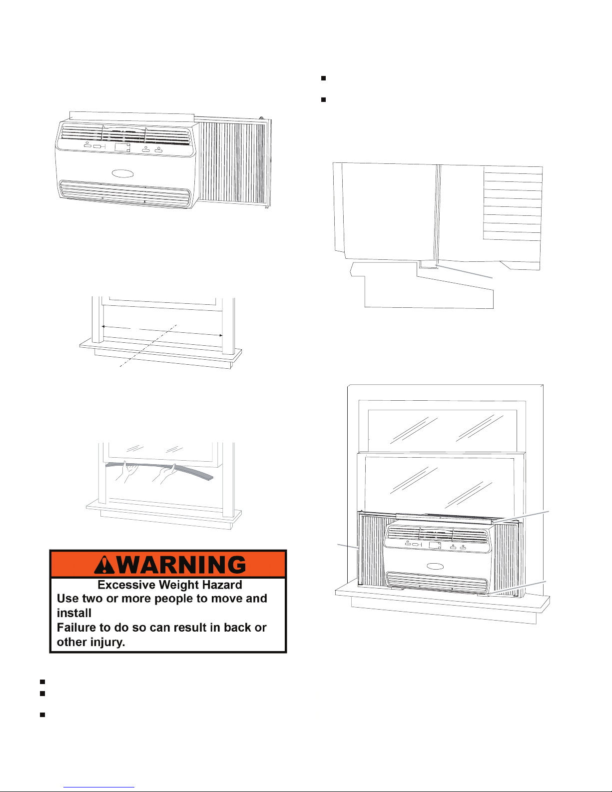
Prepare Wi ndow fo r Installaon
1. Measure the width of the window opening.
2. Mark the center line on the inside windowsill.
3. Aach the foam seal with adhesive strip to the boom of the
upper window.
Posion Air Condioner
NOTES:
Handle the air condioner gently.
Be sure your air condioner does not fall out of the opening
during installaon or removal.
The place where the power cord exits the air condioner
should be no more than 6 183 cm) from a grounded outlet.
Do not block the air intake or discharge louvers in the front
panel.
Do not block the louvers on the outside of the air condioner.
A. Width of window opening
B. Center line
B
A
1. Using 2 or more people, gently place the air condioner into
the window and center it according to the center line marked
earlier. Check that the boom channel of the air condioner is
against the windowsill.
2. Lower the window sash behind the top channel to hold the air
condioner in place.
NOTE: Yo ur model may differ from the one shown.
A. Air condioner
B. Boom channel
C Windowsill
D. Outside
B
A
C
D
A. Side curtain against window channel
B. Window sash behind top channel
C. Boom channel in behind windowsill
A
B
C
Aach Side Curtains to Window
1. Pull the right-hand curtain out unl it fits into the window
channel.
2. Use a 1/8" drill bit to drill a starter hole through the top hole in
the side curtain and into the window sash.
3. Slide the side curtain frame into the top channel on the top of
the air condioner and the track on the boom of the air
condioner.
4. Repeat above steps for the le-hand side curtain and frame.
Position Air Conditioner
the air conditioner.
2-4
 Loading...