


Whirlpool W10536160, W10536161, W10536162 Installation Guide

INSTALLATION INSTRUCTIONS
SIDE TRIM COVER KIT FOR
ELECTRIC BUILT-IN SINGLE OVEN, DOUBLE OVEN AND
MICROWAVE/OVEN COMBINATION
Built-In Single Oven Side Trim Cover Kit W10536160
UL listed for use with models: WOS51EC7A, WOS92EC7A, MEW7527A, MEW9527A, WOS51EC0A,
WOS92EC0A, MEW7530A, and MEW9530A
Built-In Double Oven Side Trim Cover Kit W10536161
UL listed for use with models: WOD51EC7A, WOD93EC7A, MEW7627A, MEW9627A, WOD51EC0A,
WOD93EC0A, MEW7630A, and MEW9630A
Built-In Microwave/Oven Combination Side Trim Cover Kit W10536162
UL listed for use with models: WOC54EC7A, WOC54EC0A, WOC95EC0A, and MMW9730A
INSTRUCTIONS D’INSTALLATION
ENSEMBLE DE GARNITURES DÉCORATIVES LATÉRALES
POUR FOUR ÉLECTRIQUE ENCASTRÉ SIMPLE, DOUBLE ET
COMBINÉ MICRO-ONDES/CONVENTIONNEL
Ensemble de garnitures décoratives latérales pour four encastré simple W10536160
Utilisation homologuée UL pour les modèles : WOS51EC7A, WOS92EC7A, MEW7527A, MEW9527A,
WOS51EC0A, WOS92EC0A, MEW7530A et MEW9530A
Ensemble de garnitures décoratives latérales pour four encastré double W10536161
Utilisation homologuée UL pour les modèles : WOD51EC7A, WOD93EC7A, MEW7627A, MEW9627A,
WOD51EC0A, WOD93EC0A, MEW7630A et MEW9630A
Ensemble de garnitures décoratives latérales pour four encastré combiné
micro-ondes/conventionnel W10536162
Utilisation homologuée UL pour les modèles : WOC54EC7A, WOC54EC0A, WOC95EC0A et MMW9730A
Table of Contents/Table des matières
BUILT-IN SINGLE OVEN, DOUBLE OVEN AND
MICROWAVE/OVEN COMBINATION SAFETY............................2
INSTALLATION REQUIREMENTS................................................2
Tools and Parts ............................................................................2
Location Requirements................................................................2
INSTALLATION INSTRUCTIONS..................................................3
Install Side Trim Cover Kit............................................................3
Install Electric Built-in Single Oven, Double Oven and
MWO/Combination Oven.............................................................4
Complete Installation ...................................................................4
SÉCURITÉ DU FOUR ENCASTRÉ SIMPLE, DOUBLE ET
COMBINÉ MICRO-ONDES/CONVENTIONNEL...........................5
EXIGENCES D'INSTALLATION.....................................................5
Outillage et pièces........................................................................5
Exigences d’emplacement...........................................................5
INSTRUCTIONS D’INSTALLATION...............................................6
Installation de l'ensemble de garnitures décoratives latérales....6
Installation du four électrique encastré simple, double et
combiné micro-ondes/conventionnel..........................................7
Achever l’installation ....................................................................7
W10533088A
BUILT-IN SINGLE OVEN, DOUBLE OVEN AND
You can be killed or seriously injured if you don't immediately
You
can be killed or seriously injured if you don't
follow
All safety messages will tell you what the potential hazard is, tell you how to reduce the chance of injury, and tell you what can
happen if the instructions are not followed.
Your safety and the safety of others are very important.
We have provided many important safety messages in this manual and on your appliance. Always read and obey all safety
messages.
This is the safety alert symbol.
This symbol alerts you to potential hazards that can kill or hurt you and others.
All safety messages will follow the safety alert symbol and either the word “DANGER” or “WARNING.”
These words mean:
follow instructions.
instructions.
DANGER
WARNING
A
B
L
MICROWAVE/OVEN COMBINATION SAFETY
INSTALLATION REQUIREMENTS
Tools and Parts
Gather the required tools and parts before starting installation.
Read and follow the instructions provided with any tools listed
here.
Tools needed
■ Phillips screwdriver
■ Measuring tape
Parts supplied
■ Level
■ Flat-blade screwdriver
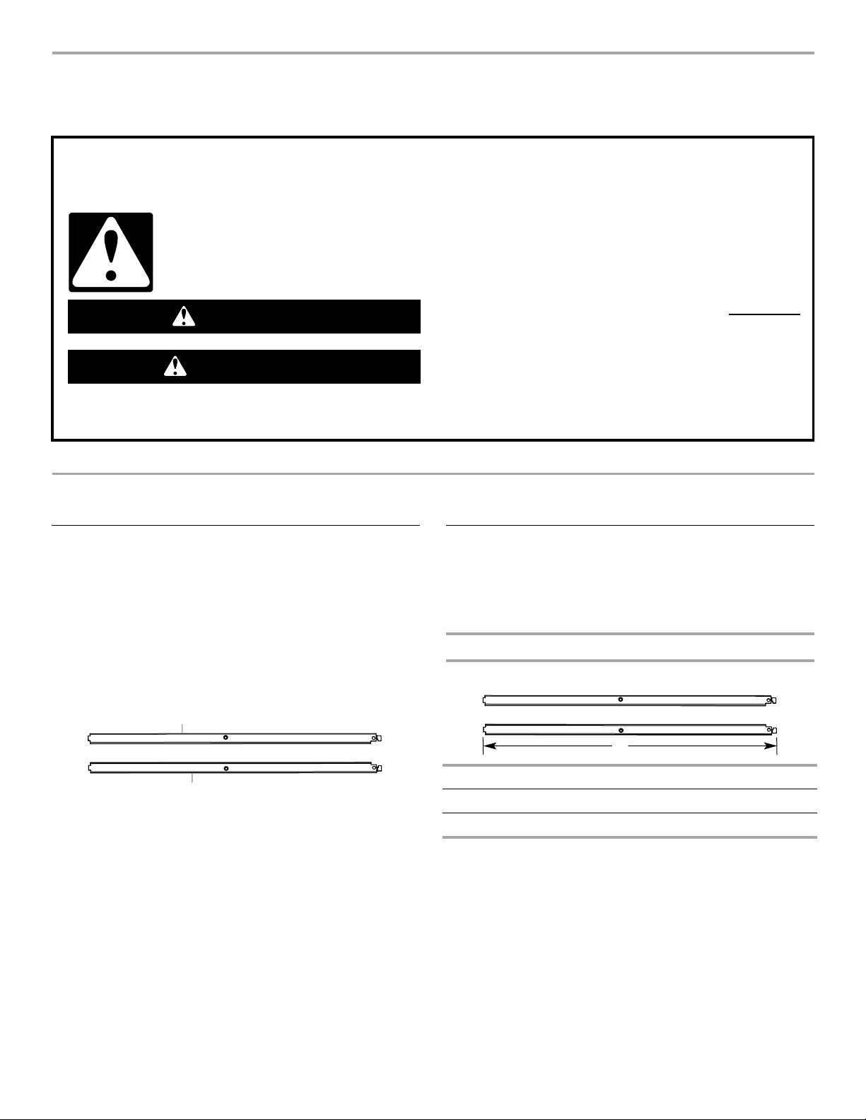
A. Left side trim cover
B. Right side trim cover
IMPORTANT: Observe all governing codes and ordinances.
■ Follow the instructions below along with the instructions in
the Electric Built-In Single Oven, Double Oven and
Microwave/Oven Combination Installation Instructions.
Product Dimensions
Side Trim Cover Kits
Single Built-In Oven L = 23¹⁄₁₆" (58.5 cm)
Double Built-In Oven L = 45¹³⁄₁₆" (116.4 cm)
MWO/Combination Built-In Oven L = 36⁷⁄₈" (93.6 cm)
Location Requirements
2

INSTALLATION INSTRUCTIONS
WARNING
Electrical Shock Hazard
Disconnect power before servicing.
Replace all parts and panels before operating.
Failure to do so can result in death or electrical shock.
A
B
C
WARNING
Excessive Weight Hazard
Use two or more people to move and install oven.
Failure to do so can result in back or other injury.
A
C
D
E
B
Install Side Trim Cover Kit
Follow the instructions below to install the Side Trim Cover Kit on
a built-in oven.
1. Disconnect power.
2. Remove the oven door(s). For more information, see the
“Remove Oven Door” section in the oven Installation
Instructions. If the built-in oven is already installed in the
cabinet, continue with Step 3. If the built-in oven is not
installed into the cabinet, go to Step 5.
3. Use a Philips screwdriver to remove the #8-14 x1" screws
fastening the oven to the cabinet. Use a flat-blade screwdriver
to remove the grommets from the mounting rail hole by
inserting the screwdriver into the grommet and giving a
clockwise ¼ turn.
4. Using 2 or more people, pull the oven 1" (2.5 cm) out of the
cabinet cutout. Use the oven opening as an area to grip.
NOTE: Pull against the seal area of the oven front frame when
lifting the oven out of the cabinet. Do not pull against the
outside edges.
5. Remove the lower screw from each side of the control panel.
Tilt the control panel out enough to insert the left and right
side trim covers behind the control panel. Align the side trim
cover to the top and side of the mounting rail.
A. Mounting rail
B. Mounting rail hole
C. Grommet
Right side rear view shown
A. Control panel
B. Mounting rail top
C. Lower screw
D. Right side trim cover
E. Mounting rail side
3