

Page 1

LEVELING FEET INSTALLATION INSTRUCTIONS
27" (68.6 CM) AND 30" (76.2 CM) ELECTRIC BUILT-IN
MICROWAVE/OVEN COMBINATION
INSTRUCTIONS D'INSTALLATION DES PIEDS DE
NIVELLEMENT FOUR CONVENTIONNEL ET FOUR À
MICRO-ONDES ÉLECTRIQUES, COMBINÉS ET ENCASTRÉS
DE 27" (68,6 CM) ET 30" (76,2 CM)
Table of Contents/Table des matières
BUILT-IN MICROWAVE/OVEN COMBINATION SAFETY...........2
INSTALLATION REQUIREMENTS................................................2
Tools and Parts ............................................................................2
Built-In Microwave/Oven Combination
Location Requirements................................................................ 3
LEVELING FEET INSTALLATION INSTRUCTIONS.....................4
Prepare Built-In Microwave/Oven Combination..........................4
Remove Oven Door......................................................................4
Positioning Oven Feet for Multiple Cabinet
Cutout Heights ............................................................................. 4
SÉCURITÉ DU FOUR À MICRO-ONDES ET DU FOUR
CONVENTIONNEL COMBINÉS ET ENCASTRÉS........................7
Outils et pièces.............................................................................7
Exigences d'emplacement de l'ensemble four à
micro-ondes et four conventionnel encastrés .............................7
INSTRUCTIONS D'INSTALLATION DES PIEDS DE
NIVELLEMENT................................................................................9
Préparation de l'ensemble des fours encastrés
(micro-ondes/conventionnel) .......................................................9
Dépose de la porte du four ..........................................................9
Positionnement des pieds du four pour des ouvertures
d'encastrement dans le placard de hauteur différente................9
IMPORTANT:
Save for local electrical inspector's use.
IMPORTANT :
À conserver pour consultation par l'inspecteur local des installations électriques.
W10518287A
Page 2
BUILT-IN MICROWAVE/OVEN COMBINATION SAFETY
Your safety and the safety of others are very important.
We have provided many important safety messages in this manual and on your appliance. Always read and obey all safety
messages.
This is the safety alert symbol.
This symbol alerts you to potential hazards that can kill or hurt you and others.
All safety messages will follow the safety alert symbol and either the word “DANGER” or “WARNING.”
These words mean:
You can be killed or seriously injured if you don't immediately
DANGER
WARNING
All safety messages will tell you what the potential hazard is, tell you how to reduce the chance of injury, and tell you what can
happen if the instructions are not followed.
follow instructions.
can be killed or seriously injured if you don't
You
instructions.
follow
INSTALLATION REQUIREMENTS
Tools and Parts
Gather the required tools and parts before starting installation.
Read and follow the instructions provided with any tools listed
here.
Tools ne ed ed
■ Phillips screwdriver
■ Measuring tape
■ Level
■ Flat-blade screwdriver
Parts supplied
■ Four #8-18 x ½" screws - oven feet
■ Bottom vent trim
■ Two rear feet (Part Number W10318219)
■ Two front feet (Part Numbers W10471952 and W10471956)
2
Page 3
Built-In Microwave/Oven Combination Location Requirements
IMPORTANT: Observe all governing codes and ordinances.
■ Cabinet opening dimensions that are shown must be used.
Given dimensions provide minimum clearance with oven.
■ Recessed installation area must provide complete enclosure
around the recessed portion of the oven.
■ Grounded electrical supply is required. See “Electrical
Requirements” section.
■ Electrical supply junction box should be located 3" (7.6 cm)
maximum below the support surface when the oven is
installed in a wall cabinet. A 1" (2.5 cm) minimum diameter
hole should have been drilled in the left rear corner of the
support surface to pass the appliance cable through to the
junction box.
■ Oven support surface must be solid, level and flush with
bottom of cabinet cutout. Floor must be able to support a
total weight (microwave and built-in oven) of 208 lbs (95 kg)
for 27" (68.6 cm) models or 249 lbs (113 kg) for 30" (76.2 cm)
models.
IMPORTANT: To avoid damage to your cabinets, check with
your builder or cabinet supplier to make sure that the
materials used will not discolor, delaminate or sustain other
damage. This oven has been designed in accordance with
the requirements of UL and CSA International and complies
with the maximum allowable wood cabinet temperatures of
194°F (90°C).
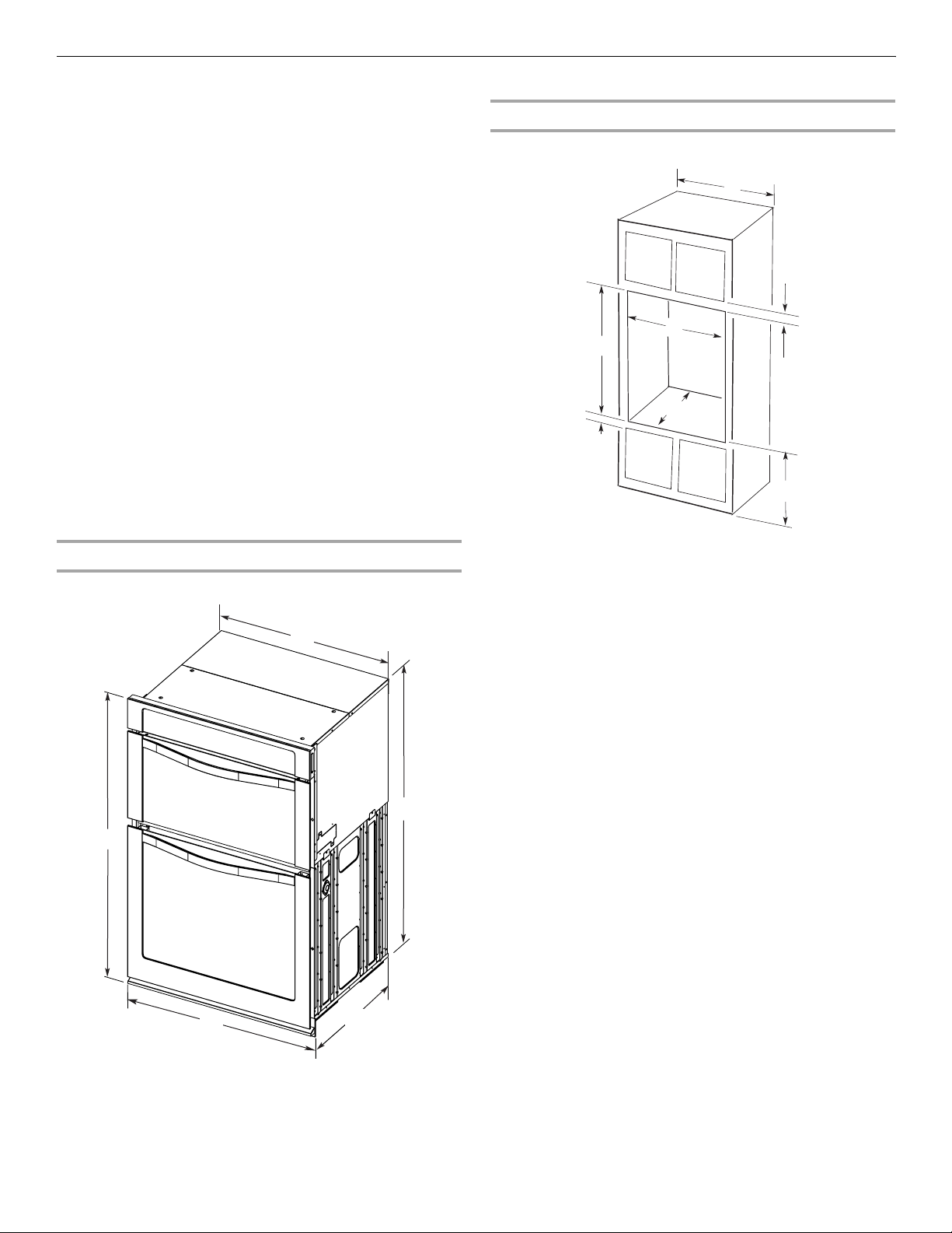
Cabinet Dimensions
27" (68.6 cm) and 30" (76.2 cm) Ovens
A
B
D
F
G
E
C
Product Dimensions
27" (68.6 cm) and 30" (76.2 cm) Ovens
A
27" (68.6 cm) models
A. 27" (68.6 cm) min. cabinet
width
B. 1" (2.5 cm) top of cutout to
bottom of upper cabinet door
C. 19
¹⁄₄
" (48.9 cm) bottom of
B
cutout to floor is
recommended.
¹⁄₄
" (10.2-48.9 cm) bottom
4"-19
of cutout to floor is acceptable.
D. 25
¹⁄₂
" (64.8 cm) cutout width
¹⁄₂
" (3.8 cm) min. bottom of
E. 1
cutout to top of cabinet door
⁵⁄₁₆
" (105 cm)* recommended
F. 4 1
cutout height
G. 24" (60.7 cm) cutout depth
30" (76.2 cm) models
30
" (76.2 cm) min. cabinet
A.
width
B. 1" (2.5 cm) top of cutout to
bottom of upper cabinet door
C. 19
¹⁄₄
" (48.9 cm) bottom of
cutout to floor is
recommended.
¹⁄₄
" (10.2-48.9 cm) bottom
4"-19
of cutout to floor is acceptable.
D. 28
¹⁄₂
" (72.4 cm) cutout width
¹⁄₂
" (3.8 cm) min. bottom of
E. 1
cutout to top of cabinet door
⁵⁄₁₆
" (105 cm)* recommended
F. 4 1
cutout height
G. 24" (60.7 cm) cutout depth
*NOTE: The cabinet height can be between 41" to 42¼"
C
(104.1 cm to 107.3 cm) or 42⁷⁄₈" to 43⁵⁄₁₆" (108.9 cm to 110.0 cm)
for microwave/oven combination.
E
27" (68.6 cm) models
42⁹⁄₁₆
" (108.0 cm) overall height
A.
B. 25
⁷⁄₁₆
" (64.6 cm) recessed width
C. 41" (104.1 cm) recessed height
¹⁄₄
" (59.1 cm) max. recessed
D. 23
depth
E. 27" (68.6 cm) overall width
D
30" (76.2 cm) models
42⁹⁄₁₆
" (108.0 cm) overall height
A.
B. 28
¹⁄₂
" (72.3 cm) recessed width
C. 41" (104.1 cm) recessed height
¹⁄₄
" (59.1 cm) max. recessed
D. 23
depth
E. 30" (76.2 cm) overall width
3
Page 4
LEVELING FEET INSTALLATION INSTRUCTIONS
A
A
Prepare Built-In Microwave/Oven
Combination
1. Decide on the final location for the oven. Locate existing
wiring to avoid drilling into or severing wiring during
installation.
WARNING
Excessive Weight Hazard
Use two or more people to move and install oven.
Failure to do so can result in back or other injury.
2. To avoid floor damage, set the oven onto cardboard prior to
installation. Do not use handle or any portion of the front
frame for lifting.
3. Remove the shipping materials and tape from the oven.
4. Remove the hardware package from inside the bag
containing literature.
5. Remove and set aside racks and other parts from inside the
oven.
6. Move oven and cardboard close to the oven’s final location.
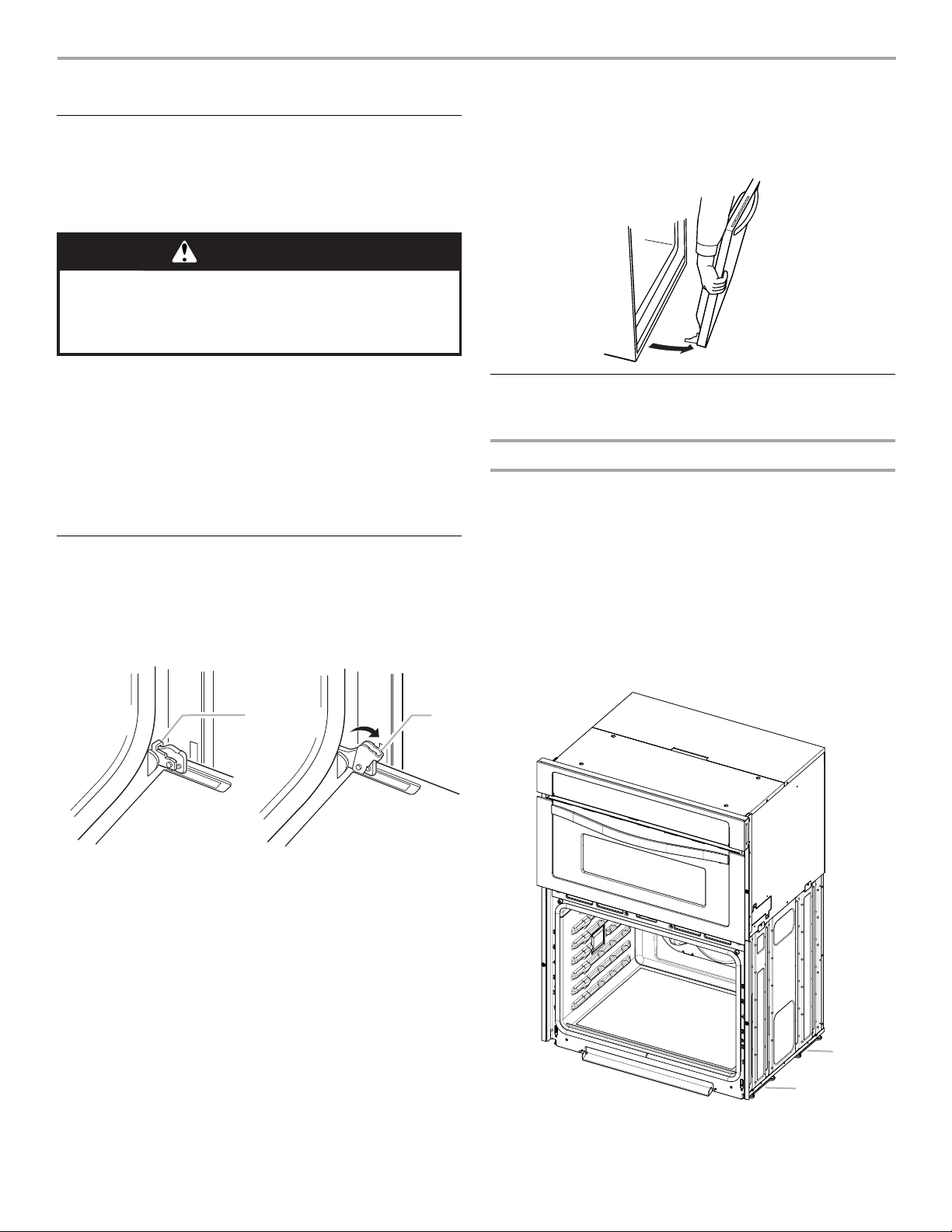
3. Grasp the edges of the oven door with both hands and close
the oven door until it will no longer close. Lift and pull oven
door toward you and remove. Set the oven door aside on a
covered work surface.
Positioning Oven Feet for Multiple Cabinet
Cutout Heights
Combo Ovens
The positioning of the oven feet allow a combo oven to be
installed in a cutout height between 41¹⁄₈" (104.5 cm) and 43⁵⁄₁₆"
(110.0 cm). Refer to the following instructions to position the feet
for the size of your cabinet cutout.
Remove Oven Door
IMPORTANT: Use both hands to remove oven door(s).
1. Open the oven door.
2. Locate the oven door latches in both corners of the oven
door, and rotate the latches forward to the unlocked position.
A. Oven door latch in locked
position
B. Oven door latch in unlocked
position
Cutout height is between 41¹⁄₈" (104.5 cm) and 41½"
(105.5 cm)
The oven feet do not need to be changed. The combo is
configured correctly as received.
NOTE: Do not remove the spacers.
Go to the “Make Electrical Connection” section of the Installation
Instructions that came with the product.
B
A. Spacers
4
A
Page 5

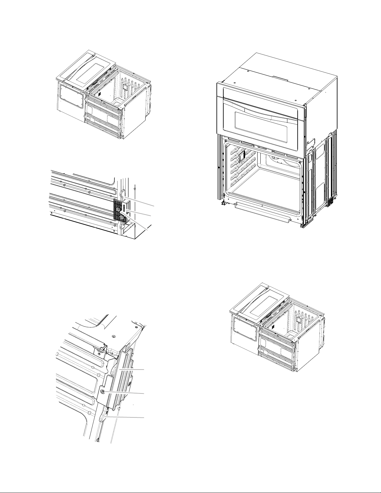
Cutout Height is between 41¹³⁄₁₆" (106.2 cm) and 42¼"
A
A
B
B
(107.3 cm)
1. Using 2 or more people, place the combo oven on its back on
a covered surface.
2. Install one of the rear feet (Part Number W10318219) on the
left rear spacer using a #8-18 x ½" screw.
NOTE: Position the rear foot so the long side of the foot is
facing toward the top of the oven.
5. In the same manner, install the front foot (Part Number
W10471956) on the right front of the oven.
6. Using 2 or more people, place the oven in its upright position.
B
C
A. Spacer
B. Rear foot
C. #8-18 x ½" screw
3. In the same manner, install the other rear foot (Part Number
W10318219) on the right rear of the oven.
4. Install the front foot (Part Number W10471952) on the left
front spacer using a #8-18 x ½" screw.
NOTE: Position the front foot so the long side of the foot is
facing toward the inside of the oven.
7. Go to the “Make Electrical Connection” section of the
Installation Instructions that came with the product.
Cutout Height is between 42⁷⁄₈" (108.9 cm) and
43⁵⁄₁₆" (110.0 cm)
1. Using 2 or more people, place the oven on its back on a
covered surface.
2. Install one of the rear feet (Part Number W10318219) on the
left rear spacer using a #8-18 x ½" screw.
NOTE: Position the rear foot so the short side of the foot is
facing toward the top of the oven.
A. Front foot
B. #8-18 x ½" screw
C. Spacer
A
C
C
A. Spacer
B. Rear foot
C. #8-18 x ½" screw
5
Page 6

3. In the same manner, install the other rear foot (Part Number
A
B
W10318219) on the right rear of the oven.
4. Install the front foot (Part Number W10471956) on the left
front using a #8-18 x ½" screw.
NOTE: Position the front foot so the long side of the foot is
facing away from the oven as shown.
C
5. In the same manner, install the front foot (Part Number
W10471952) on the right front of the oven.
6. Using 2 or more people, place the oven in its upright position.
A. Front foot
B. #8-18 x ½" screw
C. Spacer
7. Go to the “Make Electrical Connection” section of the
Installation Instructions that came with the product.
6
Page 7

SÉCURITÉ DU FOUR À MICRO-ONDES ET DU FOUR
CONVENTIONNEL COMBINÉS ET ENCASTRÉS
Votre sécurité et celle des autres est très importante.
Nous donnons de nombreux messages de sécurité importants dans ce manuel et sur votre appareil ménager. Assurez-vous de
toujours lire tous les messages de sécurité et de vous y conformer.
Voici le symbole d’alerte de sécurité.
Ce symbole d’alerte de sécurité vous signale les dangers potentiels de décès et de blessures graves à vous
et à d’autres.
Tous les messages de sécurité suivront le symbole d’alerte de sécurité et le mot “DANGER” ou
“AVERTISSEMENT”. Ces mots signifient :
Risque possible de décès ou de blessure grave si vous ne
DANGER
AVERTISSEMENT
Tous les messages de sécurité vous diront quel est le danger potentiel et vous disent comment réduire le risque de blessure et
ce qui peut se produire en cas de non-respect des instructions.
suivez pas immédiatement les instructions.
Risque possible de décès ou de blessure grave si vous
ne suivez pas les instructions.
Outils et pièces
Rassembler les outils et pièces nécessaires avant d’entreprendre
l’installation. Lire et observer les instructions fournies avec
chacun des outils de la liste ci-dessous.
Outils nécessaires
■ Tournevis Phillips
■ Mètre ruban
■ Niveau
■ Tournevis à lame plate
Pièces fournies
■ Quatre vis n° 8-18 x ½" - Pieds du four
■ Garniture de l'évent inférieur
■ Deux pieds arrière (pièce numéro W10318219)
■ Deux pieds avant (pièces numéros W10471952 et
W10471956)
Exigences d'emplacement de l'ensemble
four à micro-ondes et four conventionnel
encastrés
IMPORTANT : Observer les dispositions de tous les codes et
règlements en vigueur.
■ Respecter les dimensions indiquées pour la cavité
d'installation entre les placards. Ces dimensions prennent en
compte les dégagements de séparation nécessaires.
■ L'espace d'installation doit permettre la formation d'une
enceinte complète autour de la partie encastrée du four.
■ Une source d'électricité avec liaison à la terre est nécessaire.
Voir la section “Spécifications électriques”.
■ Le boîtier de raccordement doit être situé au maximum à
3" (7,6 cm) au-dessous de la surface de support lorsque le
four est installé dans un placard mural. Un trou de diamètre
1" (2,5 cm) ou plus doit avoir été percé dans l'angle arrière
gauche de la surface de support pour le passage du câble
d'alimentation de l'appareil jusqu'au boîtier de connexion.
■ La surface de support du four doit être robuste, horizontale et
en affleurement avec le bas de la cavité d’encastrement du
placard. Le plancher doit être capable de supporter un poids
total (four à micro-ondes et four encastré) de 208 lb (95 kg)
pour les modèles de 27" (68,6 cm) ou de 249 lb (113 kg) pour
les modèles de 30" (76,2 cm).
IMPORTANT : Afin d'éviter tout dommage aux placards,
consulter le constructeur de la maison ou le fabricant des
placards afin de déterminer si les matériaux utilisés pourraient
subir un changement de couleur, une déstratification ou d'autres
dommages. Ce four a été conçu conformément aux exigences
des normes UL et CSA International et respecte les températures
maximales autorisées de 194°F (90°C) pour les placards en bois.
7
Page 8

Dimensions du produit
Dimensions du placard
Fours de 27" (68,6 cm) et 30" (76,2 cm)
B
A
E
Modèles de 27" (68,6 cm)
A. Hauteur hors-tout
⁹⁄₁₆
" (108 cm)
42
B. Largeur d'encastrement
25
⁷⁄₁₆
" (64,6 cm)
C. Hauteur d'encastrement
41" (104,1 cm)
D. Profondeur d'encastrement
23
¹⁄₄
" (59,1 cm) max.
E. Largeur hors-tout
27" (68,6 cm)
Modèles de 30" (76,2 cm)
A. Hauteur hors-tout
⁹⁄₁₆
42
B. Largeur d'encastrement
28¹
C. Hauteur d'encastrement
41" (104,1 cm)
D. Profondeur d'encastrement
23
¹⁄₄
E. Largeur hors-tout
30" (76,2 cm)
D
" (108 cm)
⁄₂
" (72,3 cm)
" (59,1 cm) max.
Fours de 27" (68,6 cm) et 30" (76,2 cm)
A
B
D
F
C
G
E
C
Modèles de 27" (68,6 cm)
A. Largeur du placard
27" (68,6 cm) min.
B. 1" (2,5 cm) entre le sommet de
l'ouverture et le bas de la porte
du placard supérieur
C. Une hauteur de 19
entre le bas de l'ouverture et le
plancher est recommandée.
Une hauteur de 4" (10,2 cm) à
¹⁄₄
" (48.9 cm) entre le bas de
19
l'ouverture et le plancher est
acceptable.
D. Largeur de l'ouverture
25½" (64,8 cm)
E. 1½" (3,8 cm) min. entre le bas
de l'ouverture et le haut de la
porte du placard
F. Hauteur de l'ouverture
recommandée 41
G. Profondeur de l'ouverture 24"
(60,7 cm)
¹⁄₄
" (48,9 cm)
⁵⁄₁₆
'' (105 cm)*
Modèles de 30" (76,2 cm)
A. Largeur du placard
30" (76,2 cm) min.
B. 1" (2,5 cm) entre le sommet de
l'ouverture et le bas de la porte
du placard supérieur
C. Une hauteur de 19
entre le bas de l'ouverture et le
plancher est recommandée.
Une hauteur de 4" (10,2 cm) à
¹⁄₄
" (48.9 cm) entre le bas de
19
l'ouverture et le plancher est
acceptable.
D. Largeur de l'ouverture
28½" (72,4 cm)
E. 1½" (3,8 cm) min. entre le bas de
l'ouverture et le haut de la porte
du placard
F. Hauteur de l'ouverture
recommandée 41
(105 cm)*
G. Profondeur de l'ouverture 24"
(60,7 cm)
¹⁄₄
" (48,9 cm)
⁵⁄₁₆
''
*REMARQUE : Pour un ensemble four à micro-ondes/four
traditionnel, la hauteur du placard peut être comprise entre 41"
(104,1 cm) et 42¼" (107,3 cm) ou 42⁷⁄₈" (108,9 cm) et 43⁵⁄₁₆"
(110 cm).
8
Page 9

INSTRUCTIONS D'INSTALLATION DES PIEDS DE NIVELLEMENT
A
A
3. Saisir les bords de la porte du four avec les deux mains et
Préparation de l'ensemble des fours
encastrés (micro-ondes/conventionnel)
1. Choisir l'emplacement final pour l'installation du four. Repérer
le câblage existant pour éviter de le percer ou de
l'endommager lors de l'installation.
AVERTISSEMENT
Risque du poids excessif
Utiliser deux ou plus de personnes pour déplacer et
installer le four.
Le non-respect de cette instruction peut causer
une blessure au dos ou d'autre blessure.
fermer la porte du four jusqu'à la position où la fermeture de
la porte n'est plus possible. Soulever et tirer la porte du four
vers soi et enlever la porte. Conserver la porte du four à part
sur une surface de travail couverte.
2. Pour éviter d'endommager le plancher, placer le four sur une
feuille de carton avant l'installation. Lors des opérations de
levage, ne pas prendre prise sur la poignée ou sur une autre
partie du châssis avant.
3. Enlever les matériaux d'emballage et les rubans adhésifs du
four.
4. Enlever le matériel à l'intérieur du sachet de documentation.
5. Enlever et conserver à part les grilles et autres composants
qu'on trouve à l'intérieur du four.
6. Approcher le four et le carton de l'emplacement final du four.
Dépose de la porte du four
IMPORTANT : Employer les deux mains pour enlever la/les
porte(s) du four.
1. Ouvrir la porte du four.
2. Identifier les loquets de la porte du four dans les deux angles
de la porte; faire pivoter les loquets vers l'avant jusqu'à la
position de déverrouillage.
B
Positionnement des pieds du four pour des
ouvertures d'encastrement dans le placard
de hauteur différente
Fours combinés
En modifiant le positionnement des pieds du four, on peut
installer un four combiné dans une cavité d'encastrement d'une
hauteur comprise entre 41¹⁄₈" (104,5 cm) et 43⁵⁄₁₆" (110 cm).
Consulter les instructions suivantes pour adapter la position des
pieds à la taille de la cavité d'encastrement.
La hauteur de la cavité d’encastrement est comprise entre
41¹⁄₈" (104,5 cm) et 41½" (105,5 cm)
Les pieds du four n'ont pas besoin d'être remplacés. Le four
combiné a été correctement configuré à sa sortie d'usine.
REMARQUE : Ne pas retirer les cales d'espacement.
Passer à la section “Raccordement électrique” des instructions
d’installation fournies avec le produit.
A. Loquet de la porte du four en
position de verrouillage
B. Loquet de la porte du four en
position de déverrouillage
A
A. Cales d'espacement
9
Page 10
La hauteur de la cavité d’encastrement est comprise entre
A
A
B
41¹³⁄₁₆" (106,2 cm) et 42¼" (107,3 cm)
1. À l'aide d'au moins 2 personnes, placer le four combiné sur
sa partie arrière, sur une surface couverte.
2. Installer un pied arrière (pièce numéro W10318219) sur la cale
d'espacement arrière gauche avec une vis n° 8-18 x ½".
REMARQUE : Positionner le pied arrière de façon à ce que le
côté long du pied soit orienté vers le sommet du four.
5. Installer le pied avant (pièce numéro W10471956) sur la partie
avant droite du four en effectuant les mêmes opérations.
6. À l’aide d'au moins deux personnes, placer le four en position
verticale.
B
C
A. Cale d'espacement
B. Pied arrière
C. Vis n° 8-18 x ½"
3. Installer l'autre pied arrière (pièce numéro W10318219) sur la
partie arrière droite du four en effectuant les mêmes
opérations.
4. Installer le pied avant (pièce numéro W10471952) sur la cale
d'espacement avant gauche avec une vis n° 8-18 x ½".
REMARQUE : Positionner le pied avant de façon à ce que le
côté long du pied soit orienté vers l'intérieur du four.
7. Passer à la section “Raccordement électrique” des
instructions d’installation fournies avec le produit.
La hauteur de la cavité d’encastrement est comprise entre
42⁷⁄₈" (108,9 cm) et 43⁵⁄₁₆" (110,0 cm)
1. À l'aide d'au moins 2 personnes, placer le four sur sa partie
arrière, sur une surface couverte.
10
A. Pied avant
B. Vis n° 8 - 18 x ½"
C. Cale d'espacement
C
Page 11

2. Installer un pied arrière (pièce numéro W10318219) sur la cale
B
A
B
d'espacement arrière gauche avec une vis n° 8-18 x ½".
REMARQUE : Positionner le pied arrière de façon à ce que le
côté court du pied soit orienté vers le sommet du four.
A
C
A. Cale d'espacement
B. Pied arrière
C. Vis n° 8-18 x ½"
3. Installer l'autre pied arrière (pièce numéro W10318219) sur la
partie arrière droite du four en effectuant les mêmes
opérations.
4. Installer le pied avant (pièce numéro W10471956) sur la cale
d'espacement avant gauche avec une vis n° 8-18 x ½".
REMARQUE : Positionner le pied avant de façon à ce que le
côté long du pied soit orienté dos au four tel qu'illustré.
5. Installer le pied avant (pièce numéro W10471952) sur la partie
avant droite du four en effectuant les mêmes opérations.
6. À l’aide d'au moins 2 personnes, placer le four en position
verticale.
A. Pied avant
B. Vis n° 8 - 18 x ½"
C. Cale d'espacement
7. Passer à la section “Raccordement électrique” des
instructions d’installation fournies avec le produit.
C
11
Page 12

W10518287A
© 2012.
All rights reserved.
Tous droits réservés.
Printed in U.S.A.
Imprimé aux É.-U.
7/12
 Loading...