

Page 1

DRYER INSTALLATION INSTRUCTIONS
GAS (U.S.A. AND CANADA)
ELECTRIC (CANADA ONLY)
INSTRUCTIONS D’INSTALLATION DE LA SÉCHEUSE
À GAZ (É.-U. ET CANADA)
ÉLECTRIQUE (CANADA UNIQUEMENT)
Para una version de estas intrucciones en Español, visite www.Whirlpool.com
TABLE OF CONTENTS
DRYER SAFETY..............................................................................2
INSTALLATION REQUIREMENTS ................................................4
Tools and Parts ............................................................................4
Optional Equipment .....................................................................4
Location Requirements................................................................5
ELECTRIC DRYER POWER HOOKUP – CANADA ONLY
Electrical Requirements ...............................................................8
GAS DRYER POWER HOOKUP.................................................... 9
Gas Supply Requirements ...........................................................9
Make Gas Connection ...............................................................10
Electrical Requirements .............................................................10
VENTING .......................................................................................11
Venting Requirements................................................................11
Plan Vent System.......................................................................12
Install Vent System.....................................................................13
INSTALL LEVELING LEGS...........................................................13
CONNECT VENT...........................................................................13
CONNECT INLET HOSE
(STEAM MODELS)........................................................................13
LEVEL DRYER ..............................................................................14
COMPLETE INSTALLATION .......................................................14
TROUBLESHOOTING ..................................................................15
..........8
TABLE DES MATIÈRES
SÉCURITÉ DE LA SÉCHEUSE ....................................................17
EXIGENCES D’INSTALLATION...................................................19
Outillage et pièces......................................................................19
Équipement facultatif .................................................................19
Exigences d’emplacement.........................................................19
RACCORDEMENT DE L’ALIMENTAT
SÉCHEUSE ÉLECTRIQUE...........................................................23
Spécifications électriques ..........................................................23
RACCORDEMENT DE L’ALIMENTATION
À LA SÉCHEUSE À GAZ ..............................................................24
Alimentation en gaz....................................................................24
Raccordement au gaz................................................................25
Spécifications électriques
ÉVACUATION................................................................................26
Exigences concernant l’évacuation ...........................................26
Planification du système d’évacuation
Installation du système d’évacuation.........................................28
INSTALLATION DES PIEDS DE NIV
RACCORDEMENT DU CONDUIT D’ÉVACUATION ..................29
RACCORDEMENT DES TUYAUX D’ALIMENTATION
(MODÈLES À VAPEUR)
RÉGLAGE DE L’APLOMB DE LA
ACHEVER L’INSTALLATION .......................................................30
DÉPANNAGE.................................................................................31
..........................................................25
................................................................29
ION À LA
......................................27
ELLEMENT........................29
SÉCHEUSE...........................30
W10471645B
W10471647B - SP
Page 2
DRYER SAFETY
2
Page 3
3
Page 4
INSTALLATION REQUIREMENTS
Tools and Parts
Gather the required tools and parts before starting installation. Read
and follow the instructions provided with any tools listed here.
For All Installations:
Steam Models
■ Flat-blade screwdriver
■ #2 Phillips screwdriver
■ Adjustable wrench that
opens to 1" (25 mm) or
hex-head socket wrench
(for adjusting dryer feet)
■ Level
■ Vent clamps
■ Caulking gun and compound
(for installing new exhaust
vent)
■ Tin snips (new vent
installations)
■ 1/4" nut driver
(recommended)
■ Tap e me asu re
■ Pliers
Gas Installations:
■ 8" or 10" pipe wrench
■ 8" or 10" adjustable wrench
■ Pipe-joint compound
resistant to LP gas
(for gas connections)
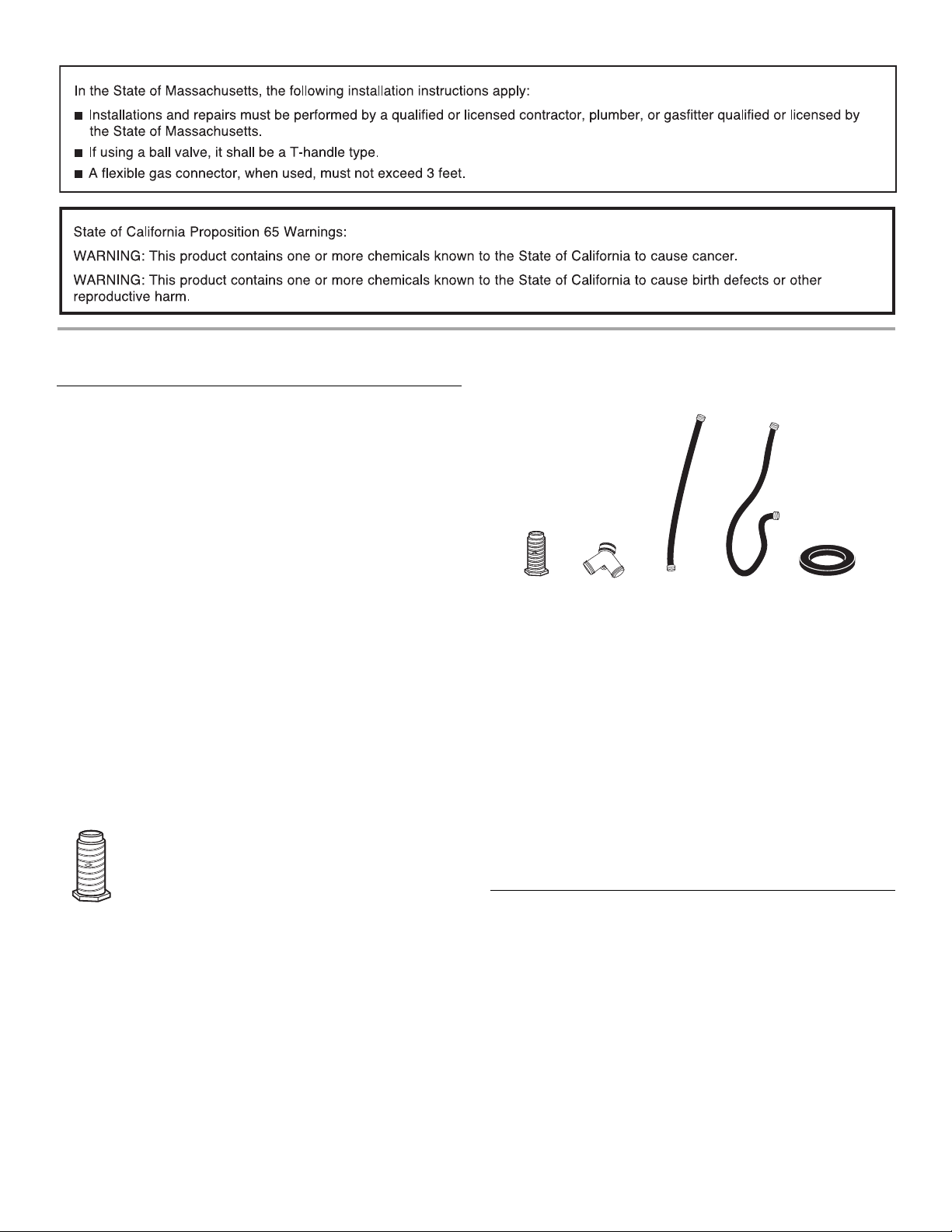
Parts supplied
Non-Steam Models
4 Leveling legs
Remove parts package from dryer drum. Check that all parts
are included.
NOTE: Do n
on a pedestal.
ot use leveling legs supplied with dryer if installing
A. Leveling legs (4)
B. “Y” connector
C. Short inlet hose
D. Long inlet hose
E. Rubber washer
Remove parts package from dryer drum. Check that all parts
are included.
NOTE: Do n
ot use leveling legs supplied with dryer if installing
on a pedestal.
Parts needed
Check local codes. Check existing electrical supply and venting.
See “Electrical Requirements” and “Venting Requirements” before
purchasing parts.
Mobile home installations require m
etal exhaust system hardware
available for purchase from the dealer from whom you purchased
your dryer. For further information, please refer to the “Assistance
or Service” section in your Use and Care Guide.
Optional Equipment
Refer to your Use and Care guide for information about the
accessories available for your dryer.
4
Page 5
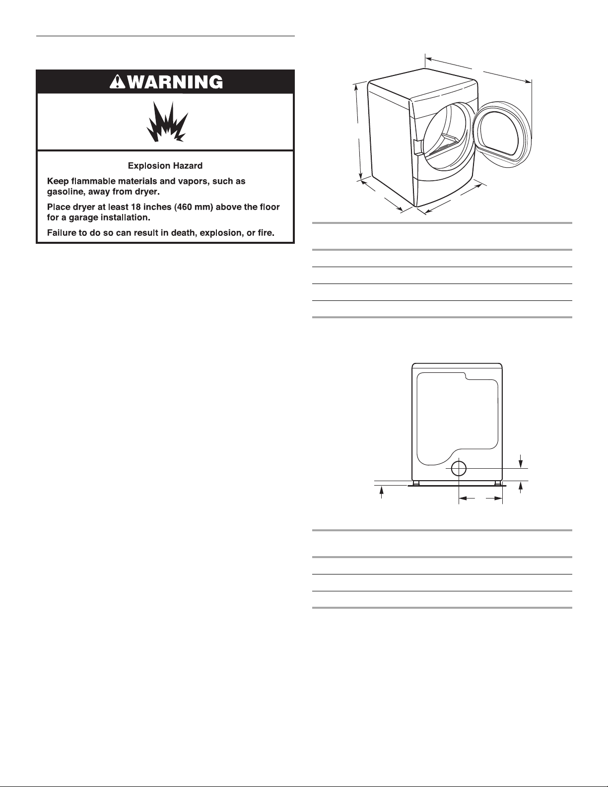
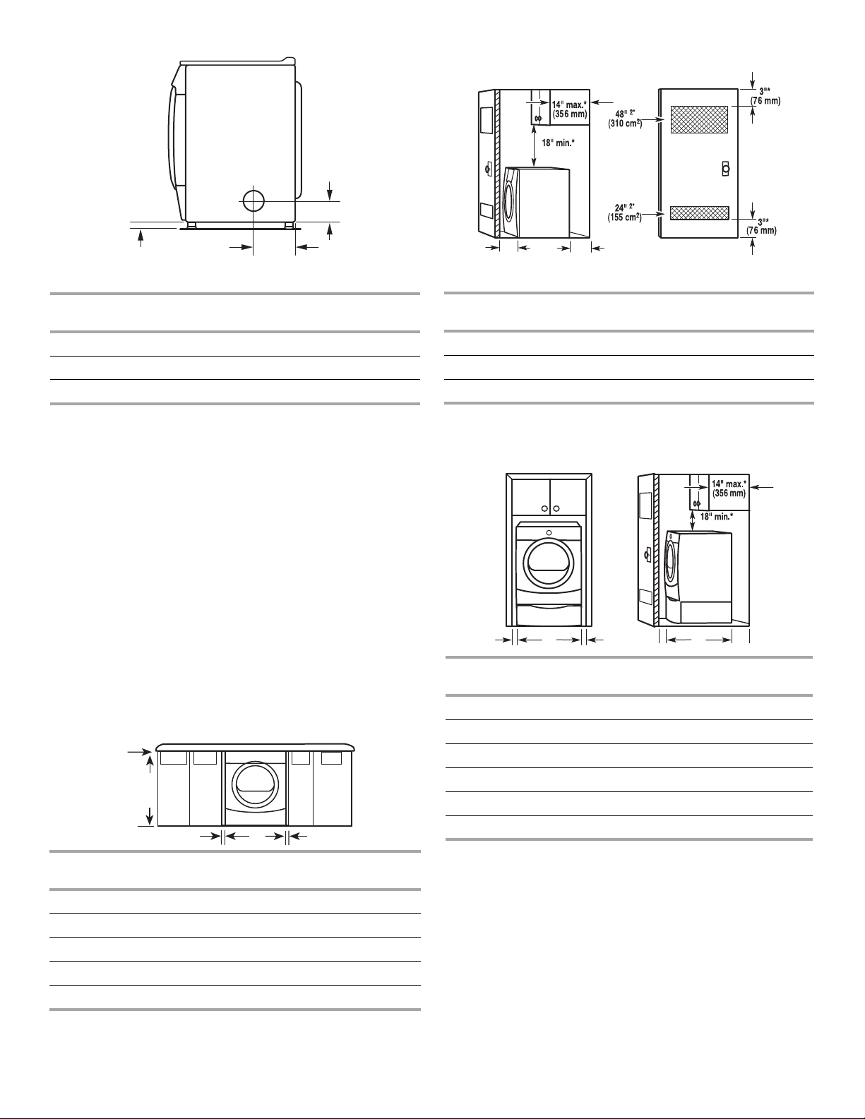
Location Requirements
Dryer Dimensions
D
A
You will need
■ A location that allows for proper exhaust installation.
See “Venting Requirements.”
■ A separate 15 or 20-amp circuit needed for gas dryers and
30-amp circuit needed for electric dryers.
■ If you are using a power supply cord, a grounded electrical
outlet located within 2 ft (610 mm) of either side of the dryer.
See “Electrical Requirements.”
■ A sturdy floor to support the total dryer weight of 200 lbs
(90.7 kg). The combined weight of a companion appliance
should also be considered.
■ A level floor with a maximum slope of 1" (25 mm) under entire
dryer. If slope is greater than 1" (25 mm), install Extended Dryer
Feet Kit, Part Number 279810. Clothes may not tumble properly
and automatic sensor cycles may not operate correctly if dryer is
not level.
■ For a garage installation, you will need to place the dryer at least
18" (460 mm) above the floor. If using a pedestal, you will need
18" (460 mm) to the bottom of the dryer.
■ Steam models only: Cold water faucets located within
4 ft (1.2 m) of the dryer, and water pressure of 20-100 psi
(137.9-689.6 kPa). You may use the cold water supply from
your washer using the “Y” connector provided.
Do not operate your dryer at temperatur
es below 45ºF (7ºC). At
lower temperatures, the dryer might not shut off at the end of an
automatic sensor cycle. This can result in longer drying times.
The dryer must not be installed or st
ored in an area where it will be
exposed to water and/or weather.
Check code requirements. Some codes limit, or
do not permit,
installation of the dryer in garages, closets, mobile homes, or
sleeping quarters. Contact your local building inspector.
No other fuel-burning appliance can be installed in the same
NOTE:
closet as a dryer.
Installation clearances
The location must be large enough to allow the dryer door to
open fully.
B
Steam
(Electric or Gas)
C
Non-Steam
(Electric or Gas)
A 38" (965 mm) 38" (965 mm)
9
B 32
/16" (827 mm) 31 1/2" (800 mm)
C 27" (686 mm) 27" (686 mm)
D 52 9/16" (1335 mm) 51 1/2" (1308 mm)
NOTE: Most installations require a minimum 5" (127 mm)
clearance behind the dryer for the exhaust vent with elbow.
Venting Dimensions
C
A
Back View
Steam
(Electric or Gas)
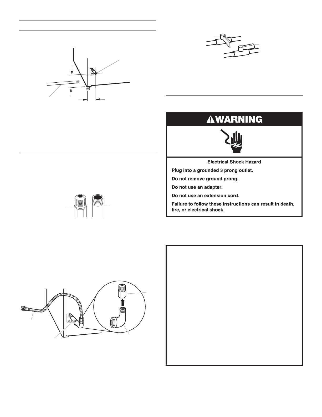
A* 1" (25 mm) 1" (25 mm)
B 14" (356 mm) 14" (356 mm)
7
C 3
/16" (87 mm) 3 7/16" (87 mm)
* Dimension A is approximate, depending on when the diamond
marking on the leveling foot is no longer visible.
B
Non-Steam
(Electric or Gas)
5
Page 6
A
Closet installation - Dryer only
A
(460 mm)
C
A
Steam
(Electric or Gas)
B
Side View
Non-Steam
(Electric or Gas)
A* 1" (25 mm) 1" (25 mm)
5
B 7
C 3
* Dimension
marking on the leveling foot is no longe
/8" (194 mm) 7 5/8" (194 mm)
3
/8" (86 mm) 3 3/8" (86 mm)
A is approximate, depending on when the diamond
r visible.
See “Venting Requirements.”
Installation spacing for recessed area or closet installation
The following spacing dimensions are recommended for this dryer.
This dryer has been tested for spacing of 0" (0 mm) clearance on the
sides an
following reasons:
■ Additional spacing should be considered for ease of installation
■ Additional clearances might be required for wall, door, and floor
■ Additional spacing should be considered on all sides of the dryer
■ For closet installation, with a door, minimum ventilation openings
■ Companion appliance spacing should also be considered.
Custom undercounter installation - Dryer only
d rear. Recommended spacing should be considered for the
and servicing.
moldings.
to reduce noise transfer.
in the top and bottom of the door are required. Louvered doors
with equivalent ventilation openings are acceptable.
A*
B C**
Side view
Steam
(Electric or Gas)
Closet door with vents
Non-Steam
(Electric or Gas)
A* 1" (25 mm) 1" (25 mm)
B 32
9
/16" (827 mm) 31 1/2" (800 mm)
C** 5" (127 mm) 5" (127 mm)
*Required spacing
**For side or bottom venting, 0" (0 mm) spacing is allowed.
Recessed or closet installation
B C D* E
Steam
(Electric or G
as)
- Dryer on pedesta
(Electric or Gas)
l
(460 mm)
F**
Non-Steam
A 1" (25 mm) 1" (25 mm)
B 27" (686 mm) 27" (686 mm)
C 1" (25 mm) 1" (25 mm)
B
C* DE*
Steam
(Electric or Gas)
Non-Steam
(Electric or Gas)
A 0" (0 mm) 0" (0 mm)
D* 1" (25 mm) 1" (25 mm)
9
E 32
/16" (827 mm) 31 1/2" (800 mm)
F** 5" (127 mm) 5" (127 mm)
*Required spacing
**For side or bottom venting, 0" (0 mm) spacing is allowed
NOTE: Some
models are not recommended for recessed or closet
installation.
B 38" (965 mm) 38" (965 mm)
C* 1" (25 mm) 1" (25 mm)
D 27" (686 mm) 27" (686 mm)
E* 1" (25 mm) 1" (25 mm)
*Required spacing
NOTE:
Some models are not recommended for undercounter
installation.
6
Page 7
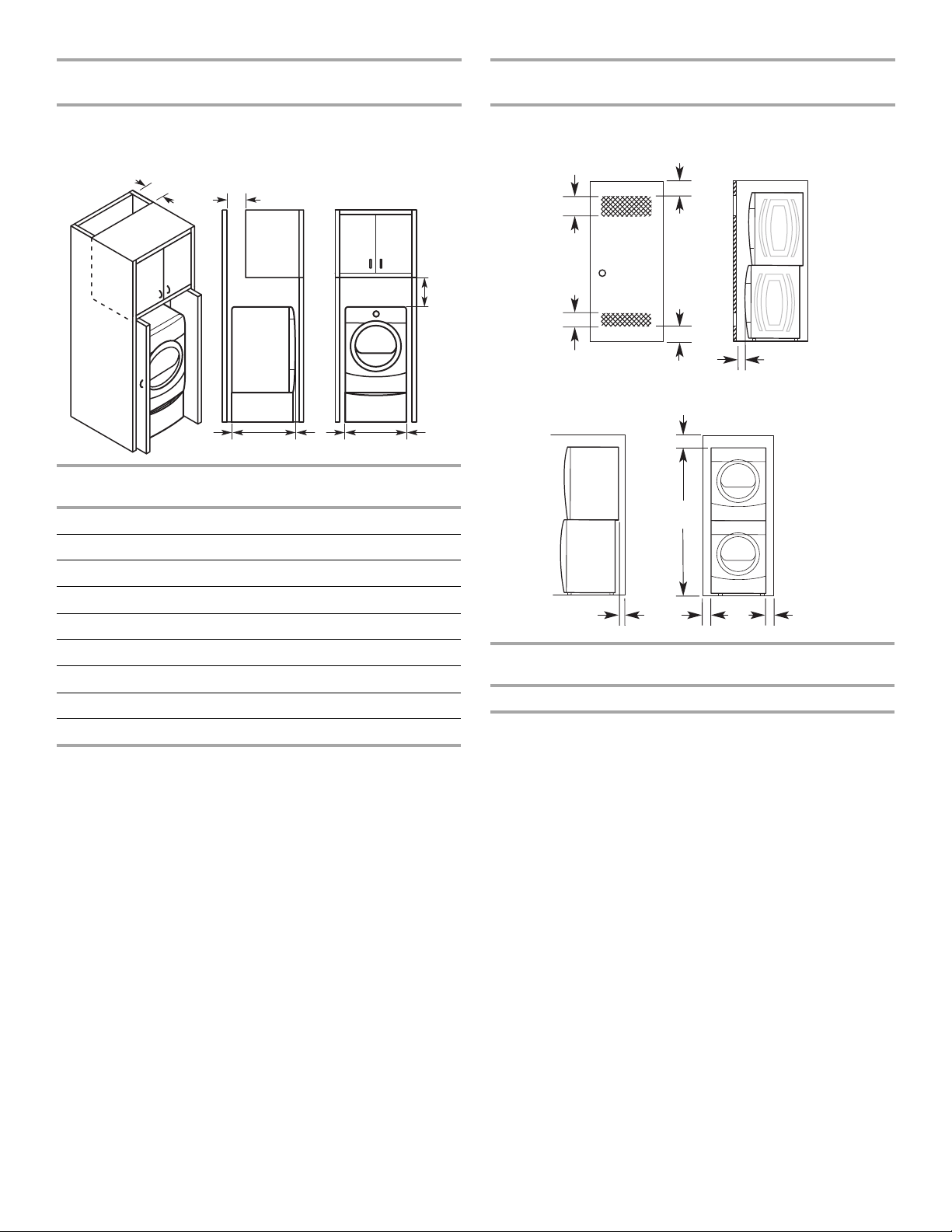
Recommended installation spacing for cabinet
installation
Recommended installation spacing for recessed or
closet installation, with stacked washer and dryer
NOTE: Some models are not recommended for cabinet installation.
■ For cabinet installation, with a door, minimum ventilation
openings in the top of the cabinet are required.
A*
B*
C*
D**
Steam
(Electric or Gas)
E
G
F*
H
Non-Steam
(Electric or Gas)
I
A* 7" (178 mm) 7" (178 mm)
B* 7" (178 mm) 7" (178 mm)
C* 9" (229 mm) 9" (229 mm)
The dimensions shown are for the recommended spacing.
48 in.2 *
2
(310 cm
)
3"* (76 mm)
3"* (76 mm)
2
24 in.
(155 cm2)
*
6"* (152 mm)
76"
(1930 mm)
1"* (25 mm)
D** 5" (127 mm) 5" (127 mm)
9
E 32
/16" (827mm) 31 1/2" (800 mm)
F* 1" (25 mm) 1" (25 mm)
G 1" (25 mm) 1" (25 mm)
H 27" (686 mm) 27" (686 mm)
I 1" (25 mm) 1" (25 mm)
*Required spacing
**For side or bottom venting, 0" (0 mm) spacing is allowed.
A*
1"
(25 mm)
27"
(686 mm)
Steam
(Electric or Gas)
1"
(25 mm)
Non-Steam
(Electric or Gas)
A* 5 ½" (140 mm) 5" (127 mm)
*Required spacing
NOTE: Some
models are not recommended for stacked recessed or
closet installation.
Mobile home - Additional installation requirements
This dryer is suitable for mobile home installations. The installation
must conform to the Manufactured Home Construction and Safety
Standard, Title 24 CFR, Part 3280 (formerly the Federal Standard for
Mobile Home Construction and Safety, Title 24, HUD Part 280) or
Standard CAN/CSA-Z240 MH.
Mobile home installations require:
All Dryers
■ Metal exhaust system hardware, which is available for purchase
from your dealer.
■ Special provisions must be made in mobile homes to introduce
outside air into the dryer. The opening (such as a nearby
window) should be at least twice as large as the dryer exhaust
opening.
For gas dryers
■ Mobile Home Installation Kit Part Number 346764. See “Tools
and Parts” section for information on ordering.
7
Page 8
ELECTRIC DRYER POWER HOOKUP – CANADA ONLY
For further information, please reference the service numbers
Electrical Requirements
It is your responsibility
■ To contact a qualified electrical installer.
■ To be sure that the electrical connection is adequate and in
conformance with the Canadian Electrical Code, C22.1-latest
edition and all local codes. A copy of the above codes standard
may be obtained from: Canadian Standards Association, 178
Rexdale Blvd., Toronto, ON M9W 1R3 CANADA.
■ To supply the required 4 wire, single phase, 120/240 volt,
60 Hz., AC only electrical supply on a separate 30-amp circuit,
f
used on both sides of the line. A time-delay fuse or circuit
breaker is recommended. Connect to an individual branch
circuit.
■ This dryer is equipped with a CSA International Certified Power
Cord intended to be plugged into a standard 14-30R wall
receptacle. The cord is 5 ft (1.52 m) in length. Be sure wall
receptacle is within reach of dryer’s final location.
located in the “Assistance or Service” section
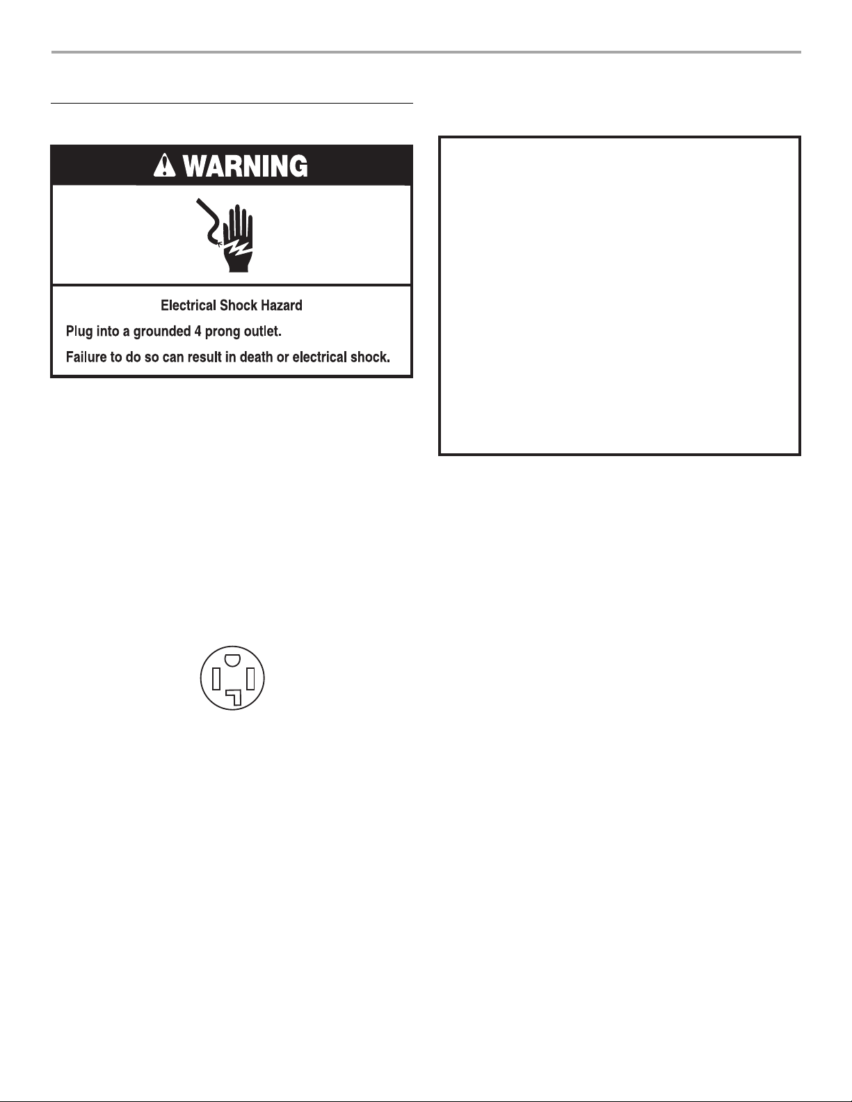
GROUNDING INSTRUCTIONS
■
For a grounded, cord-connected dryer:
This dryer must be grounded. In the event of malfunction or
breakdown, grounding will reduce the risk of electric shock
by providing a path of least resistance for electric current.
This dryer is equipped with a cord having an equipmentgrounding conductor and a grounding plug. The plug must
be plugged into an appropriate outlet that is properly
installed and grounded in accordance with all local codes
and ordinances.
WARNING: Improper connection of the equipment-
grounding conductor can result in a risk of electric shock.
Check with a qualied electrician or service representative
or personnel if you are in doubt as to whether the dryer is
properly grounded. Do not modify the plug provided with
the dryer: if it will not t the outlet, have a proper outlet
installed by a qualied electrician.
SAVE THESE INSTRUCTIONS
.
4-wire receptacle 14-30R
If using a replacement power supply cord, it is recommended that
you use Power Supply Cord Replacement Part Number 9831317.
8
Page 9
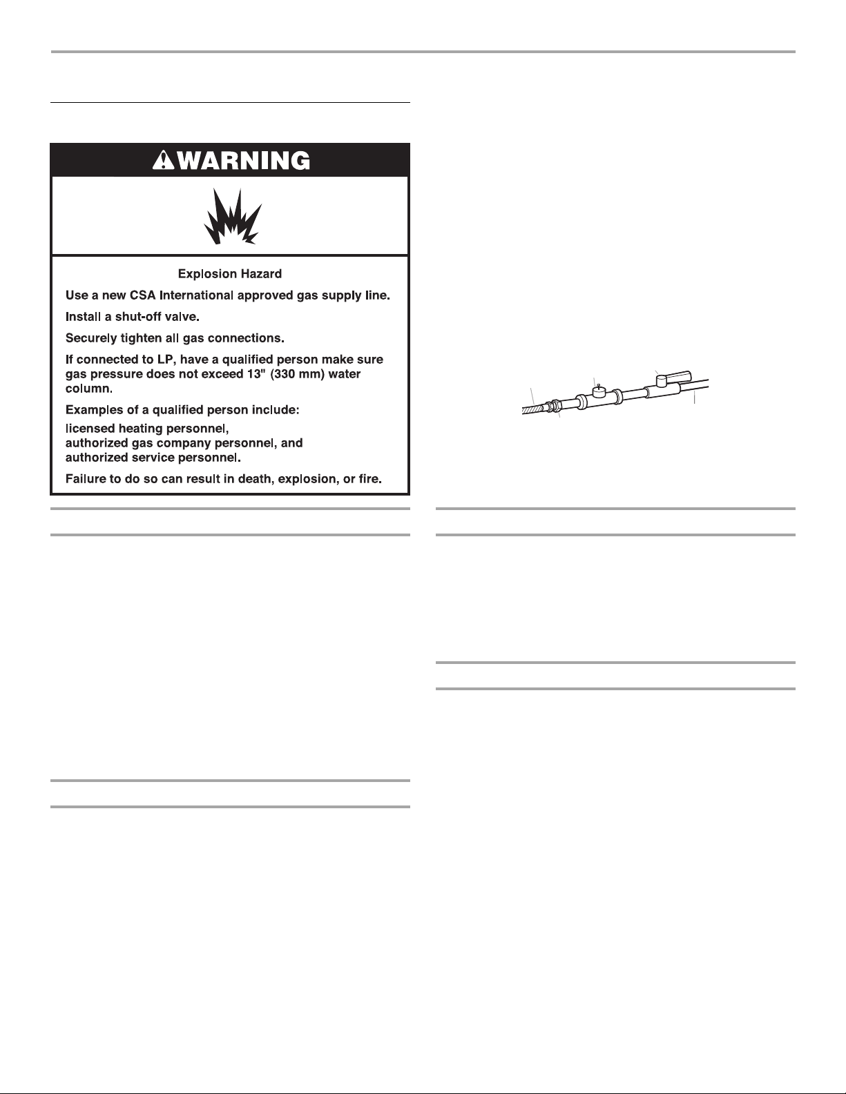
GAS DRYER POWER HOOKUP
Gas Supply Requirements
■ If your dryer has been converted to use LP gas, 3/8" LP
compatible copper tubing can be used. If the total length of the
supply line is more than 20 ft (6.1 m), use larger pipe.
NOTE: Pipe-joint compounds that resist the action of LP gas
must be used. Do not use TEFLON
■ Must include a shutoff valve:
®†
tape.
In the U.S.A.:
An individual manual shutoff valve must be installed within
six (6) feet (1.8 m) of the dryer in
accordance with the National
Fuel Gas Code, ANSI Z223.1.
In Canada:
An individual manual shutof
six(6) feet (1.8 m) of the dryer in
f valve must be installed within
accordance with the B149.1,
Natural Gas and Propane Installation Code.
The location should be easy to reach for opening and closing.
E
D
NPT minimum
C. 1/8"
plugged tapping
D. 1/2" NPT gas supply line
E. Gas shutoff valve
A
B
A. 3/8" flexible gas connector
B. 3/8" pipe to flare adapter
fi
tting
C
Gas Type
Natural gas:
This dryer is equipped for use with Natu
ral gas. It is design-certified
by CSA International for LP (propane or butane) gases with
appropriate conversion.
■ Your dryer must have the correct burner for the type of gas in
your home. Burner information is located on the rating plate in
the door well of your dryer. If this information does not agree
with the type of gas available, contact your dealer or call the
phone numbers referenced in the “Assistance or Service”
section.
LP gas conversion:
Conversion must be made by a qualified technician.
No attempt shall be made to con
vert the appliance from the gas
specified on the model/serial rating plate for use with a different gas
without consulting your gas company.
Gas supply line
■ Must include 1/8" NPT minimum plugged tapping accessible
for test gauge connection, immediately upstream of the gas
con
nection to the dryer. See illustration.
■ 1/2" IPS pipe is recommended.
■ 3/8" approved aluminum or copper tubing is acceptable for
lengths under 20 ft (6.1 m) if local codes and gas supplier
permit.
■ If you are using Natural gas, do not use copper tubing.
■ Lengths over 20 ft (6.1 m) should use larger tubing and a
different size adapter fitting.
Gas supply connection requirements
■ Use an elbow and a 3/8" flare x 3/8" NPT adapter fitting
between the flexible gas connector and the dryer gas pipe, as
needed to avoid kinking.
■ Use only pipe-joint compound. Do not use TEFLON
■ This dryer must be connected to the gas supply line with a listed
®†
tape.
flexible gas connector that complies with the standard for
connectors for gas appliances, ANSI Z21.24 or CSA 6.10.
Burner input requirements
Elevations above 10,000 ft (3,048 m):
■ When installed above 10,000 ft (3,048 m) a 4% reduction of the
burner Btu rating shown on the model/serial number plate is
required for each 1,000 ft (305 m) increase in elevation.
Gas supply pressure testing
■ The dryer must be disconnected from the gas supply piping
system during pressure testing at pressures greater than 1/2 psi.
†
®TEFLON is a registered trademark of E.I. Du Pont De Nemours and Company.
9
Page 10
Dryer gas pipe
3. Open the shutoff valve in the supply line. The valve is open when
the handle is parallel to the gas pipe.
■ The gas pipe that comes out through the rear of your dryer has a
3/8" male pipe thread.
*6¼"
*6¼"
(159 mm)
(159 mm)
A
A
A. 1/2" NPT gas supply line
B. 3/8" NPT dryer pipe
1½"
1½"
(38 mm)
(38 mm)
B
B
*NOTE: If the dryer is mounted on a pedestal, the gas pipe
height must be an additional 10" (254 mm) or 15.5" (394 mm)
fr
om the floor, depending on the pedestal model. For a garage
installation, the gas pipe height must be an additional
18" (457 mm) from the floor.
Make Gas Connection
1. Remove the red cap from the gas pipe.
2. Usin
g a wrench to tighten, connect the gas supply to the dryer.
Use pipe-joint compound on the threads of all non-flared male
fittings. If flexible metal tubing is used, be sure there are no kinks.
A
B
A. Closed valve
B. Open valve
4. Test all connections by brushing on an approved noncorrosive
leak-detection solution. Bubbles will show a leak. Correct any
leak found.
Electrical Requirements
A
A. Flared male fitting
B. Non-flared male fitting
B
NOTE: For LP gas connections, you must use pipe-joint
compound resistant to the action of LP gas. Do not use
TEFLON
®†
tape.
A combination of pipe fittings must be used to connect the dryer
e existing gas line. Shown is a recommended connection.
to th
Your connection may be different, according to the supply line
type, size and location.
D
A
B
A. 3/8" flexible gas
connector
B. 3/8" dryer pipe
C. 3/8" to 3/8" pipe elbow
D. 3/8" pipe-to-flare
ad
apter fitting
C
■ 120 Volt, 60 Hz., AC only, 15- or 20-amp fused electrical
supply is required. A time-delay fuse or circuit breaker is
recommended. It is also recommended that a separate circuit
serving only this dryer be provided.
GROUNDING INSTRUCTIONS
■
For a grounded, cord-connected dryer:
This dryer must be grounded. In the event of malfunction or
breakdown, grounding will reduce the risk of electric shock
by providing a path of least resistance for electric current.
This dryer is equipped with a cord having an equipmentgrounding conductor and a grounding plug. The plug must
be plugged into an appropriate outlet that is properly
installed and grounded in accordance with all local codes
and ordinances.
WARNING: Improper connection of the equipment-
grounding conductor can result in a risk of electric shock.
Check with a qualied electrician or service representative
or personnel if you are in doubt as to whether the dryer is
properly grounded. Do not modify the plug provided with
the dryer: if it will not t the outlet, have a proper outlet
installed by a qualied electrician.
SAVE THESE INSTRUCTIONS
†
®TEFLON is a registered trademark of E.I. Du Pont De Nemours and Company.
10
Page 11

VENTING
Venting Requirements
WARNING: To reduce the risk of fire, this dryer MUST BE
EXHAUSTED OUTDOORS.
IMPORTANT: Obse
The dryer exhaust must not be connected into any gas vent,
imney, wall, ceiling, attic, crawlspace, or a concealed space
ch
of a building.
rve all governing codes and ordinances.
Flexible metal vent
■ Flexible metal vents are acceptable only if accessible for
cleaning.
■ Flexible metal vent must be fully extended and supported when
the dryer is in its final location.
■ Remove excess flexible metal vent to avoid sagging and kinking
that may result in reduced airflow and poor performance.
■ Do not install flexible metal vent in enclosed walls, ceilings, or
floors.
■ The total length of flexible metal vent should not exceed
7¾ ft. (2.4 m).
Elbows
45° elbows provide better airflow than 90° elbows.
Good Better
Clamps
■ Use clamps to seal all joints.
■ Exhaust vent must not be connected or secured with screws or
other fastening devices that extend into the interior of the duct
and catch lint. Do not use duct tape.
If using an existing vent system
■ Clean lint from the entire length of the system and make sure
exhaust hood is not plugged with lint.
■ Replace any plastic or metal foil vent with rigid heavy metal
or flexible metal vent.
■ Review vent system chart. Modify existing vent system if
necessary to achieve the best drying performance. Only rigid
or flexible metal vent shall be used for exhausting.
If this is a new vent system
Vent material
■ Use a heavy metal vent. Do not use plastic or metal foil vent.
■ 4" (102 mm) heavy metal exhaust vent and clamps must be
used.
4" (102 mm) heavy metal exhaust vent
Vent products can be purchased from your dealer or by calling
Whirlpool Service. For more information, see the “Assistance or
Service” section.
Rigid metal vent
■ For best drying performance, rigid metal vents are
recommended.
■ Rigid metal vent is recommended to avoid crushing and kinking.
Clamp
Exhaust
A and B: Recommended hood styles.
C: Acceptable hood style.
B
4"
(102 mm)
A
2½"
4"
(102 mm)
4"
(102 mm)
A. Louvered hood style
B. Box hood style
C. Angled hood style
■ An exhaust hood should cap the vent to keep rodents and
(64 mm)
insects from entering the home.
■ Exhaust hood must be at least 12" (305 mm) from the ground
or any object that may be in the path of the exhaust (such as
flower
s, rocks or bushes, snow line, etc.).
11
Page 12

■ Do not use an exhaust hood with a magnetic latch.
A
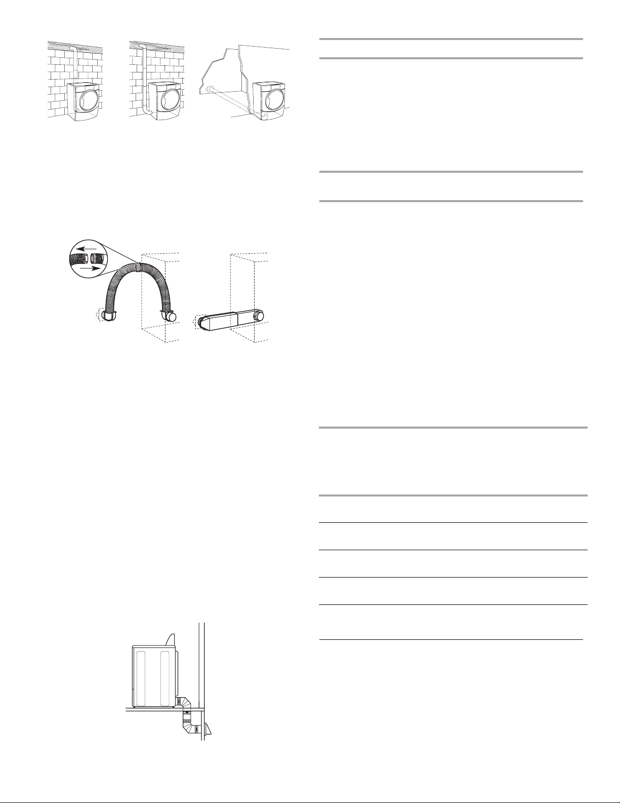
Plan Vent System
Choose your exhaust installation type
Recommended exhaust installations
Typical installations vent the dryer from the rear of the dryer. Other
installations are possible.
B
C
D
E
F
G
H
A. Dryer
B. Elbow
C. Wall
D. Exhaust hood
E. Clamps
F. Rigid metal or flexible metal vent
G. Vent length necessary to connect elbows
H. Exhaust outlet
Optional exhaust installations
This dryer can be converted to exhaust out the right side, left side, or
through the bottom. If you prefer, you may contact your local dealer
to have the dryer converted.
WARNING
A
A. Standard rear offset exhaust installation
B. Left or right side exhaust installation
C. Bottom exhaust installation
B
C
Alternate installations for close clearances
Venting systems come in many varieties. Select the type best
for your installation. Two examples of close-clearance installations
e shown. Refer to the manufacturer’s instructions.
ar
A B
A. Over-the-top installation (also available with one offset elbow)
B. Periscope installation
NOTE: The following kits for close-clearance alternate installations
are available for purchase. Please see the “Assistance or Service”
section to order.
■ Over-the-Top Installation:
Part Number 4396028
■ Periscope Installation (For use with dryer vent to wall vent
mismatch):
Part Number 4396037 - 0" (0 mm) to 18" (460 mm) mismatch
Part Number 4396011 - 18" (460 mm) to 29"(737 mm) mismatch
Part Number 4396014 - 29" (737 mm) to 50" (1270 mm)
mismatch
Special provisions for mobile home installations
The exhaust vent must be securely fastened to a noncombustible
portion of the m
beneath the mobile home. Terminate the exhaust vent outside.
obile home structure and must not terminate
Fire Hazard
Cover unused exhaust holes with the following kit:
W10470674 (midnight grey)
Contact your local dealer.
Failure to follow these instructions can result in death,
re, electrical shock, or serious injury.
Determine vent path
■ Select the route that will provide the straightest and most direct
path outdoors.
12
Page 13

■ Plan the installation to use the fewest number of elbows
and turns.
■ When using elbows or making turns, allow as much room
as possible.
■ Bend vent gradually to avoid kinking.
■ Use the fewest 90° turns possible.
Determine vent length and elbows needed for best
drying performance
■ Use the following vent system chart to determine type of vent
material and hood combinations acceptable to use.
NOTE: D
Vent system chart.
Exhaust systems longer than those specified will:
■ Shorten the life of the dryer.
■ Reduce performance, resulting in longer drying times and
The vent system chart provides venting requirements that will help
to achieve the best drying performance.
o not use vent runs longer than those specified in the
increased energy usage.
Vent system chart
NOTE: Side and bottom exhaust installations have a 90º turn inside
the dryer. To determine maximum exhaust length, add one 90º turn
to the chart.
Number
90º elbows
0 Rigid metal 64ft (20 m) 58ft (17.7 m)
1 Rigid metal 54 ft (16.5 m) 48 ft (14.6 m)
2 Rigid metal 44 ft (13.4 m) 38 ft (11.6 m)
3 Rigid metal 35 ft (10.7 m) 29 ft (8.8 m)
4 Rigid metal 27 ft (8.2 m) 21 ft (6.4 m)
Type of vent Box /louvered
hoods
Angled
hoods
Install Vent System
1. Install exhaust hood. Use caulking compound to seal exterior wall
opening around exhaust hood.
onnect vent to exhaust hood. Vent must fit inside exhaust hood.
2. C
Secure vent to exhaust hood with 4" (102 mm) clamp.
3. Run
vent to dryer location. Use the straightest path possible. See
“Determine vent path” in “Plan Vent System.” Avoid 90º turns.
Use clamps to seal all joints. Do not use duct tape, screws, or
other fastening devices that extend into the interior of the vent to
secure vent, because they can catch lint.
INSTALL LEVELING LEGS
2. F
irmly grasp the body of the dryer (not the console panel). Gently
lay the dryer on the cardboard. See illustration.
3. Examine the leveling legs. Find the diamond marking.
4. Screw the legs into the leg holes by hand. Use a wrench to finish
turning the legs until the diamond marking is no longer visible.
5. Place a carton cor
the 2 dryer back corners. Stand the dryer up. Slide the dryer on
the corner posts until it is close to its final location. Leave enough
room to connect the exhaust vent.
ner post from dryer packaging under each of
CONNECT VENT
1. Using a 4" (102 mm) clamp, connect vent to exhaust outlet in
dryer. If connecting to existing vent, make sure the vent is clean.
The dryer vent must fit over the dryer exhaust outlet and inside the
exhaust hood. Check that the vent is secured to exhaust hood
with a 4" (102 mm) clamp.
2. Mo
ve dryer into its final location. Do not crush or kink vent.
3. (On gas models) Check that there are no kinks in the flexible
gas line.
4. Once the exhaust vent connection is made, remove the corner
posts and cardboard.
CONNECT INLET HOSE
(STEAM MODELS)
The dryer must be connected to the cold water faucet using the new
inlet hoses. Do not use old hoses.
1. T
urn cold water faucet off and remove washer inlet hose.
2. Remove old rubber wash
rubber washer provided. If space permits, attach the brass female
end of the “Y” connector to the cold water faucet.
If “Y” connector can be attached directly to cold water
NOTE:
faucet, go to Step 6. If “Y” connector cannot be attached
directly to the cold water faucet, the short hose must be used.
Continue with Step 3.
3. Attach short hose to cold water faucet. Screw on coupling by
hand until it is seated on faucet.
er from inlet hose and replace with new
1. To avoid damaging the floor, use a large flat piece of cardboard
from the dryer carton. Place cardboard under the entire back
edge of the dryer.
13
Page 14

4. Using pliers, tighten the couplings with an additional two-thirds
turn.
NOTE: Do not overtighten. Damage to the coupling can result.
5. Attach
6. One en
7. Attach
8. Using pliers, tighten the couplings an additional two-thirds turn.
9. Attach
10. Using pliers, tighten the coupling an additional two-thirds turn.
11. Check that the water faucets ar
12. Check for leaks around “Y” connector, faucet, and hoses.
“Y” connector to brass male end of small hose. Screw on
coupling by hand until it is seated on connector.
d of the long hose has a wire mesh strainer inside the
coupling. Attach this end to the “Y” connector.
washer cold inlet hose to other end of “Y” connector.
Screw on coupling by hand until it is seated on connector.
A
A. Inlet to cold water
Do not overtighten. Damage to the coupling can result.
NOTE:
other end of long hose to fill valve at bottom of dryer back
panel. Screw on coupling by hand until it is seated on fill valve
connector.
Do not overtighten. Damage to the coupling can result.
NOTE:
e on.
LEVEL DRYER
Check the levelness of the dryer. Check levelness first side to side,
then front to back.
If the dryer is not level, prop up the dryer using a wood block. Use a
wrench to adjust the legs up or down and check again for levelness.
COMPLETE INSTALLATION
1. Check that all parts are now installed. If there is an extra part, go
back through the steps to see which step was skipped.
2. Check that you have all of your tools.
3. Dispose of/recycle all packaging materials.
eck the dryer’s final location. Be sure the vent is not crushed
4. Ch
or kinked.
5. Ch
eck that the dryer is level. See “Level Dryer.”
6. Remove the film
the dryer.
7. Wipe the dr
remove any dust.
8. Read “Dryer Use.” Electric Models Only
or power supply cord installation, plug into a grounded outlet.
9. F Gas Models Only:
eck that gas supply is on.
10. Ch
eck for leaks.
11. Ch Steam Models Only:
12. Be su
13. Ch
14. If you live in a har
All Models:
15. Select a Timed Dry heated cycle, and start the dryer. Do not select
This dryer automatically runs an installation diagnostic routine at the
start of its first cycle.
re the water faucets are on.
eck for leaks around “Y” connector, faucet, and hoses.
recommended to control the buildup of scale through the water
system in the dryer. Over time, the buildup of lime scale may clog
different parts of the water system, which will reduce product
performance. Excessive scale buildup may lead to the need for
certain part replacement or repair.
the Air Only Temperature setting.
If the dryer will not start, check
■ Controls are set in a running or “On” position.
■ Start button has been pushed firmly.
■ Dryer is plugged into a grounded 3 prong outlet and/or
electrical supply is connected.
■ Household fuse is intact and tight, or circuit breaker has
not tripped.
■ Dryer door is closed.
on the console and any tape remaining on
yer drum interior thoroughly with a damp cloth to
d water area, use of a water softener is
the following:
14
Page 15

If you receive an L2 code, there may be a problem with your
home power supply keeping the dryer’s heater from turning on.
See “Troubleshooting.”
16. When the dryer has been running for 5 minutes, open the dryer
door and feel for heat. If you feel heat, cancel cycle and close the
door.
TROUBLESHOOTING
First try the solutions suggested here and possibly avoid the cost of a service call...
Dryer Operation
Dryer will not run
■ Has a household fuse blown, or has a circuit breaker
tripped?
There may be 2 household fuses or circuit breakers for the dryer.
Check that both fuses are intact and tight, or that both circuit
breakers have not tripped. Replace the fuse or reset the circuit
breaker. If the problem continues, call an electrician.
■ Is the correct power supply available?
Electric dryers require 240-volt power supply. Check with a
qualified electrician.
■ Was a regular fuse used?
Use a time-delay fuse.
No heat
■ Has a household fuse blown, or has a circuit breaker
tripped?
The drum may be turning, but you may not have heat. Electric
dryers use 2 household fuses or circuit breakers. Replace the
fuse or reset the circuit breaker. If the problem continues, call an
electrician.
If you do not feel heat, turn off the dryer and check the following:
■ There may be 2 household fuses or circuit breakers for the
dryer. Check that both fuses are intact and tight, or that both
circuit breakers have not tripped. If there is still no heat,
contact a qualified technician.
NOTE: You may notice a odor when the dryer is first heated. This
odor is common when the heating element is first used. The odor
will go away.
■ “AF” (low airflow condition):
The dryer will continue to run when this diagnostic code is
present. Press any key to clear the code from the display and
return to the estimated time remaining.
Try the following:
■ Clean lint screen.
■ Check to see if the vent run from the dryer to the wall is
crushed or kinked.
■ Confirm the vent run from the dryer to the wall is free of lint
and debris.
■ Confirm the exterior vent exhaust hood is free of lint and
debris.
■ Confirm your vent system falls within the recommended run
length and number of elbows for the type of vent you are
using. Refer to “Plan Vent System” for details.
■ Select a Timed Dry heated cycle, and restart the dryer.
If the message persists, have your entire home venting run
cleaned.
■ “E” Variable (E1, E2, E3) service codes:
Call for service.
Dryer displaying code message
■ “PF” (power failure), check the following:
Was the drying cycle interrupted by a power failure?
Press and hold START/PAUSE to restart the dryer.
■ “L2” Diagnostic Code (low or no line voltage condition):
The drum will turn, but there may be a problem with your home
power supply keeping the dryer's heater from turning on. The
dryer will continue to run when this diagnostic code is present.
Press any key to clear the code from the display and return to
the estimated time remaining.
Try the following:
Check to see if a household fuse has blown or circuit breaker
has tripped. Electric dryers use two household fuses or
breakers. Replace the fuse or reset the circuit breaker.
Confirm the power cord is properly installed. Refer to “Electrical
Connection” for details.
Select a Timed Dry heated cycle, and restart the dryer.
If the message persists, consult a qualified electrician.
15
Page 16

Dryer Results
Clothes are not drying satisfactorily, drying times are too
long, or load is too hot
■ Is the lint screen clogged with lint?
Lint screen should be cleaned before each load.
■ Is the exhaust vent or outside exhaust hood clogged with
lint, restricting air movement?
Run the dryer for 5-10 minutes. Hold your hand under the
outside
exhaust hood to check air movement. If you do not feel
air movement, clean exhaust system of lint or replace exhaust
vent with heavy metal or flexible metal vent. See the Installation
Instructions.
■ Are fabric softener sheets blocking the grille?
Use only one fabric softener sheet, and use it only once.
■ Is the exhaust vent the correct length?
Check that the exhaust vent is not too long or has too many
tur
ns. Long venting will increase drying times. See the
Installation Instructions.
■ Is the exhaust vent diameter the correct size?
Use 4" (102 mm) diameter vent material.
■ Is the dryer located in a room with temperature below
45ºF (7ºC)?
Proper operation of dryer cycles requires temperatures above
45
ºF (7ºC).
■ Is the dryer located in a closet?
Closet doors must have ventilati
on openings at the top and
bottom of the door. The front of the dryer requires a minimum of
1" (25 mm) of airspace, and, for most installations, the r
ear of the
dryer requires 5" (127 mm). See the Installation Instructions.
16
Page 17
SÉCURITÉ DE LA SÉCHEUSE
17
Page 18

18
Page 19

EXIGENCES D’INSTALLATION
Outillage et pièces
Rassembler les outils et pièces nécessaires avant de commencer
l’installation. Lire et suivre les instructions fournies avec les outils
indiqués ici.
Pour toutes les installations :
■ Tournevis à lame plate
■ Tournevis Phillips n° 2
■ Clé à molette avec ouverture
jusqu’à 1" (25 mm) ou clé à
douille hexagonale (pour
ajuster les pieds de la
sécheuse)
■ Niveau
■ Brides de serrage
■ Pince
Installations à gaz :
■ Pistolet à calfeutrage et
composé de calfeutrage
(pour l’installation d’un
nouveau conduit
d’évacuation)
■ Cisaille de ferblantier (pour
l’installation d’un nouveau
conduit)
■ Tourne-écrou de 1/4"
(recommandé)
■ Mètre-ruban
Pièces nécessaires
Consulter les codes locaux. Vérifier l’alimentation électrique et le
circuit d’évacuation existants. Voir “Spécifications électriques “et”
Exigences concernant l’évacuation” avant d’acheter les pièces.
Les installations pour maison mobile nécessitent un
système
d’évacuation en métal disponible chez le marchand chez qui vous
avez acheté votre sécheuse. Pour en savoir plus, veuillez consulter
la section “Assistance ou service” de votre Guide d’utilisation et
d’entretien.
Équipement facultatif
Consulter votre Guide d’utilisation et d’entretien pour en savoir plus
sur les accessoires disponibles pour votre sécheuse.
Exigences d’emplacement
■ Clé à tuyau de 8" ou 10"
■ Clé à mollette de 8" ou 10"
(pour le raccordement au
■ Composé d’étanchéité des
raccords filetés - résistant
au gaz propane
gaz)
Pièces fournies :
Modèles sans vapeur
4 pieds de nivellement
Retirer le sachet de pièces du tambour de la sécheuse. Vérifier que
toutes les pièces sont présentes.
REMARQUE : Ne pas utiliser les pieds de nivellement fournis avec la sécheuse en cas d’installation sur un piédestal.
Modèles à vapeur
A. Pieds de nivellement (4)
B. Connecteur en “Y”
C. Tuyau d’alimentation court
Retirer le sachet de pièces du tambour de la sécheuse. Vérifier que
toutes les pièces sont présentes.
REMARQUE :
Ne pas utiliser les pieds de nivellement fournis avec
la sécheuse en cas d’installation sur un piédestal.
D. Long tuyau d’arrivée d’eau
E. Rondelle en caoutchouc
Il vous faudra
■ Un emplacement avec un conduit d’évacuation à proximité. Voir
“Exigences concernant l’évacuation”.
■ Un circuit distinct de 15 ou 20 A est requis pour les sécheuses à
gaz et un circuit distinct de 30 A est requis pour les sécheuses
électriques.
■ Une prise électrique avec liaison à la terre située à moins
de 2 pi (610 mm) de l’un des côtés de la sécheuse. Voir
“Spé
cifications électriques”.
■ Un plancher robuste capable de supporter un poids total
(sécheuse et charge) de 200 lb (90,7 kg). Le poids combiné d’un
appareil voisin doit également être pris en compte.
■ Un plancher de niveau ayant une pente maximale de 1" (25 mm)
sous l’ensemble de la sécheuse. Si l’inclinaison est supérieure à
1" (25 mm), installer l’ensemble de pieds d’extension de
sécheuse, pièce no 279810. Si la sécheuse n’est pas de niveau,
les vêtements peuvent ne pas culbuter convenablement et les
programmes automatiques de détection peuvent ne pas
fonctionner correctement.
■ Pour l’installation dans un garage, vous devez placer la
sécheuse à au moins 18" (460 mm) au-dessus du sol. En cas
d’utilisation d’un piédestal, il faudra 18" (460 mm) jusqu’au fond
de la sécheuse.
■ Modèles à vapeur uniquement : Les robinets d’eau froide
doivent être situés à moins de 4 pi (1,2 m) de la sécheuse
et la pression de l’eau doit être de 20 à 100 lb/po²
(137,9 à 689,6 kPa). Vous pouvez ut
droite de votre laveuse à l’aide du connecteur en “Y” fourni.
iliser l’alimentation en eau
19
Page 20

Ne pas faire fonctionner la sécheuse à des températures
inférieures à 45°F (7°C). À des températures inférieures, la
sécheuse risque de ne plus s’arrêter à la fin d’un programme
automatique. Les temps de séchage risquent alors d’augmenter.
La sécheuse ne doit pas être installée ou r
emisée dans un endroit
où elle sera exposée à l’eau et/ou aux intempéries.
Vérifier les règlements locaux. Certains codes limitent ou
n’autorisent pas l’installation des sécheuses dans un garage,
un placard, une maison mobile ou une chambre à coucher.
Communiquer avec l’inspecteur des bâtiments local.
REMARQUE : Aucun autre appareil consommant un combustible
ne doit être installé dans le même placard qu’une sécheuse.
Dimensions pour l’évacuation
C
Dégagements de séparation à respecter
L’emplacement doit être assez grand pour permettre d’ouvrir
complètement la porte de la sécheuse.
Dimensions de la sécheuse
D
A
B
Vapeur
(électrique ou à gaz)
A 38" (965 mm) 38" (965 mm)
9
B 32
/16" (827 mm) 311/2" (800 mm)
C 27" (686 mm) 27" (686 mm)
D 52 9/16" (1335 mm) 511/2" (1308 mm)
REMARQUE :
La plupart des installations requièrent un espace
minimum de 5" (127 mm) derrière la sécheuse pour le conduit
d’évacuation avec coude.
C
Sans vapeur
(électrique ou à gaz)
A
Vue arrière
Vapeur
(électrique ou à gaz)
B
Sans vapeur
(électrique ou à gaz)
A* 1" (25 mm) 1" (25 mm)
B 14" (356 mm) 14" (356 mm)
C 3 7/16" (87 mm) 3 7/16" (87 mm)
* La dimension A est approximative et dépend de la visibilité du
losange sur le pied de nivellement.
C
A
Vapeur
(électrique ou à gaz)
B
Vue latérale
Sans vapeur
(électrique ou à gaz)
A* 1" (25 mm) 1" (25 mm)
B 7
C 3
5
/8" (194 mm) 7 5/8" (194 mm)
3
/8" (86 mm) 3 3/8" (86 mm)
20
* La dimens
ion A est approximative et dépend de la visibilité du
losange sur le pied de nivellement.
Voir “Exigences concernant l’évacuation”.
Espacement pour une installation dans un encastrement ou dans un placard
On recommande les dimensions d’espacement suivantes pour cette
sécheuse. Cette sécheuse a été testée pour une installation avec
dégagement de 0" (0 mm) sur les côtés et à l’arrière. L’espacement
recommandé doit être considéré pour les raisons suivantes :
■ Prévoir davantage d’espace pour faciliter l’installation et
l’entretien.
■ Un espace supplémentaire peut être requis pour les moulures
de porte et de plancher et pour les plinthes.
Page 21

■ Un espace supplémentaire doit être envisagé de tous les côtés
A
A
de la sécheuse afin de réduire le transfert de bruit.
■ Pour installation dans un placard avec porte, on doit prévoir des
ouvertures minimales d’entrée d’air en haut et en bas de la
porte. Les portes à claire-voie offrant des ouvertures
équivalentes de passage de l’air sont acceptables.
■ Il faut aussi prendre en compte l’espace requis entre les
appareils voisins.
Installation personnalisée sous un
comptoir -
sécheuse seulement
Installation dans un encastrement ou placar
piédestal
l
d - sécheuse sur
(460 mm)
B
C* DE*
Vapeur
(électrique ou à gaz)
Sans vapeur
(électrique ou à gaz)
A 0" (0 mm) 0" (0 mm)
B 38" (965 mm) 38" (965 mm)
C* 1" (25 mm) 1" (25 mm)
D 27" (686 mm) 27" (686 mm)
E* 1" (25 mm) 1" (25 mm)
*Espacement requis
REMARQUE : Certains modèles
ne sont pas recommandés pour
une installation sous un comptoir.
Installation dans un placard - Sécheuse seulement
(460 mm)
B C D* E
Vap eur
(éle
ctrique ou à gaz)
Sans vapeur
(électrique ou à gaz)
A 1" (25 mm) 1" (25 mm)
B 27" (686 mm) 27" (686 mm)
C 1" (25 mm) 1" (25 mm)
D* 1" (25 mm) 1" (25 mm)
9
E 32
/16" (827 mm) 31 1/2" (800 mm)
F** 5" (127 mm) 5" (127 mm)
*Espacement requis
**Pour une évacuation par le côté ou
par le fond, un espacement
de 0" (0 mm) est permis.
REMARQUE :
Certains modèles ne sont pas recommandés pour
une installation dans un encastrement ou un placard.
F**
A*
B C**
Vue latérale Porte de placard avec
Vapeur
(électrique ou à gaz)
orifices d’entrée d’air
Sans vapeur
(électrique ou à gaz)
A* 1" (25 mm) 1" (25 mm)
B 32
9
/16" (827 mm) 31 1/2" (800 mm)
C** 5" (127 mm) 5" (127 mm)
*Espacement requis
** Pour une évacuation par le côté
ou par le fond, un espacement
de 0" (0 mm) est permis.
21
Page 22

Espacement recommandé pour l’installation dans
un placard
REMARQUE : Certains modèles ne sont pas recommandés pour
une installation dans un placard.
■ Pour installation dans un placard avec porte, on doit prévoir des
ouvertures minimum d’entrée d’air au sommet du placard.
Espacement recommandé pour une installation dans
un encastrement ou dans un placard, avec laveuse et
sécheuse superposées
Les dimensions indiquées sont pour l’espacement recommandé.
48 in.2 *
(310 cm2)
3"* (76 mm)
3"* (76 mm)
2
24 in.
(155 cm2)
*
6"* (152 mm)
1"* (25 mm)
Vapeur
(électrique ou à gaz)
Sans vapeur
(électrique ou à gaz)
A* 7" (178 mm) 7" (178 mm)
B* 7" (178 mm) 7" (178 mm)
C* 9" (229 mm) 9" (229 mm)
D** 5" (127 mm) 5" (127 mm)
E 32 9/16" (827 mm) 31 1/2" (800 mm)
F* 1" (25 mm) 1" (25 mm)
G 1" (25 mm) 1" (25 mm)
H 27" (686 mm) 27" (686 mm)
I 1" (25 mm) 1" (25 mm)
*Espacement requis
**Pour une évacuation par le côté ou par le fond, un espacement
0" (0 mm) est permis.
de
76"
(1930 mm)
A*
1"
(25 mm)
Vap eur
(électrique ou à gaz)
27"
(686 mm)
(électrique ou à gaz)
1"
(25 mm)
Sans vapeur
A* 5 ½" (140 mm) 5" (127 mm)
*Espacement requis
REMARQUE : Certains modèles ne sont pas recommandés pour
une installation dans un encastrement ou dans un placard.
Exigences supplémentaires concernant l’installation dans une maison mobile
Cette sécheuse peut être installée dans une maison mobile.
L’installation doit être conforme à la norme canadienne sur
les maisons préfabriquées CAN/C
SA-Z240 MH.
L’installation dans une maison mobile exige :
Spécifications électriques
■ Un système d’évacuation en métal qui peut être acheté chez
votre marchand.
■ Il faut prendre des dispositions spéciales pour l’apport d’air
extérieur dans la sécheuse lors d’une installation dans une
maison mobile. La surface de toute ouverture pour l’apport d’air
extérieur (telle qu’une fenêtre à proximité) doit être au moins
deux fois plus grande que l’ouverture de décharge de la
sécheuse.
Pour les sécheuses à gaz
■ Trousse d’installation pour maison mobile Pièce n° 346764.
Voir la section “Outillage et pièces” pour des
sur la commande.
renseignements
22
Page 23

RACCORDEMENT DE L’ALIMENTATION À
LA SÉCHEUSE ÉLECTRIQUE
Spécifications électriques
C’est à l’utilisateur qu’incombe la responsabilité de
■ Contacter un électricien qualifié.
■ S’assurer que le raccordement électrique est adéquat et
conforme au code national de l’électricité, C22.1 - dernière
édition, et à tous les codes locaux. Pour obtenir un exemplaire
des normes des codes ci-dessus, contacter : Canadian
Standards Association, 178 Rexdale Blvd., Toronto, ON M9W
1R3 CANADA.
■ L’appareil doit être alimenté uniquement par une alimentation
électrique monophasée de 120/240 V, CA seulement, 60 Hz à
4 fils, sur un circuit séparé de 30
aux deux extrémités de la ligne. On recommande d’utiliser un
fusible ou un disjoncteur temporisé. On recommande également
que cet appareil soit alimenté par un circuit indépendant.
■ Cette sécheuse est équipée d’un cordon électrique homologué
par la CSA International à introduire dans une prise murale
standard 14-30R. Le cordon mesure 5 pi (1,52 m). Veiller à ce
que la prise murale se trouve à proximité de l’emplacement
définitif de la sécheuse.
ampères, protégée par fusible
Pour en savoir plus, veuillez vous reporter aux numéros de service
qui se trouvent à la section “Assistance ou service”.
INSTRUCTIONS DE LIAISON À LA TERRE
Pour une sécheuse reliée à la terre et connectée par
un cordon :
Cette sécheuse doit être reliée à la terre. En cas de mauvais
fonctionnement ou de panne, la liaison à la terre réduira le
risque de choc électrique en offrant au courant électrique un
acheminement d'évacuation de moindre résistance. Cette
sécheuse est alimentée par un cordon électrique comportant
un conducteur relié à la terre et une che de branchement
munie d'une broche de liaison à la terre. La che doit être
branchée sur une prise appropriée qui est bien installée et
reliée à la terre conformément à tous les codes et règlements
locaux.
AVERTISSEMENT : Le raccordement incorrect de
cet appareil au conducteur de liaison à la terre peut susciter
un risque de choc électrique. En cas de doute quant à la
qualité de liaison à la terre de la sécheuse, consulter un
électricien ou un technicien ou un personnel qualié. Ne pas
modier la che de branchement fournie avec la sécheuse;
si la che ne correspond pas à la conguration de la prise de
courant, demander à un électricien qualié d'installer une
prise de courant appropriée.
CONSERVEZ CES INSTRUCTIONS
Prise murale à 4 fils (14-30R)
En cas d’utilisation d’un cordon d’alimentation de rechange, il est
recommandé d’utiliser le cordon d’alimentation électrique numéro
9831317 (pièce de rechange).
23
Page 24

RACCORDEMENT DE
L’ALIMENTATION
À LA SÉCHEUSE À GAZ
Alimentation en gaz
Canalisation d’arrivée de gaz
■ La canalisation doit comprendre un connecteur obturé (filetage
NPT 1/8
l’instrument de mesure immédiatement en amont de la
connexion d’alimentation en gaz de la sécheuse (voir
l’illustration suivante).
■ Un tuyau IPS de 1/2" est recommandé.
■ Pour les longueurs inférieures à 20 pi (6,1 m), on peut utiliser des
tuyaux approuvés de cuivre ou d’aluminium de 3/8" si les codes
locaux et le fournisseur de gaz le permettent.
■ Pour le gaz naturel, ne pas utiliser de conduits en cuivre.
■ Pour les longueurs supérieures à 20 pi (6,1 m), on peut utiliser
des tuyaux plus gros et un adaptateur de grosseur différente.
■ Si la sécheuse a été convertie au gaz de pétrole liquéfié, on peut
utiliser un tuyau en cuivre compatible avec le gaz de pétrole
liquéfié de 3/8". Si la longueur totale de la canalisation d’arrivée
de gaz est supérieure à 20 pi (6,1 m), utiliser une plus grosse
conduite.
REMARQUE : On doit utiliser un composé d’étanchéi
tuyauteries résistant à l’action du gaz de pétrole liquéfié. Ne
pas utiliser de ruban TEFLON
■ Doit comporter un robinet d’arrêt du gaz :
Au Canada :
Un robinet d’arrêt manuel individuel doit être installé à six (6)
pieds (1,8 m) de la sécheuse conformément au Natural Gas
and Propane Installation Code, B149.1.
L’emplacement doit être facilement accessible pour l’ouverture et
la fermeture.
" ou plus) accessible pour le raccordement de
®†
.
A
C
E
té des
Type de gaz
Gaz naturel :
Cette sécheuse est équipée pour une alimentation au gaz naturel.
Sa concep
l’alimentation au gaz de pétrole liquéfié (propane ou butane),
avec conversion appropriée.
■ Cette sécheuse doit être équipée du brûleur convenable,
Conversion au gaz de pétrole liquéfié :
Un technicien qualifié doit effectuer la conversion.
Ne pas entreprendre de convertir l’appareil pour l’utilisation d’un
gaz dif
d’abord consulter le fournisseur de gaz.
tion est homologuée par CSA International pour
correspondant au gaz spécifique qui alimente l’habitation.
L’information sur le brûleur se trouve sur la plaque signalétique
dans le logement de la porte de la sécheuse. Si cette
information ne correspond pas au type de gaz disponible,
communiquer avec votre marchand ou composer les numéros
indiqués dans la section “Assistance ou service”.
férent de celui indiqué sur la plaque signalétique sans
D
B
A. Connecteur de gaz souple de 3/8"
aptateur du tuyau au joint conique de 3/8"
B. Ad
C. Connecteur obturé (filetage NPT de 1/8"ou plus)
D. Canalisation d’arrivée de gaz NPT de 1/2"
E. Robinet d’arrêt du gaz
Exigences concernant le raccordement au gaz
■ Utiliser un coude et un adaptateur NPT de 3/8" x 3/8" entre le
connecteur de gaz flexible et la conduite de gaz de la sécheuse,
tel que nécessaire pour éviter le pincement.
■ Utiliser uniquement un composé d’étanchéité des tuyauteries.
Ne pas utiliser de ruban TEFLON
■ On doit raccorder la sécheuse à la conduite d’alimentation en
gaz à l’aide d’un connecteur de gaz flexible homologué qui
respecte les normes applicables aux connecteurs utilisés avec
des appareils ménagers à gaz, CSA 6.10.
®†
.
24
†
®TEFLON est une marque déposée de E.I. Du Pont De Nemours et Compagnie.
Page 25

Exigences concernant l’alimentation du brûleur
A
Altitudes supérieures à 10 000 pi (3048 m) :
■ Lors d’une installation au-dessus de 10 000 pi (3 048 m),
une réduction de 4 % du débit thermique (en BTU)
la plaque signalétique est nécessaire pour chaque tranche de
1 000 pi (305 m) d’élévation.
Épreuve sous pression de l’alimentation en gaz
■ La sécheuse doit être déconnectée du système de canalisations
d’alimentation en gaz lors de tout test de pression à des
pressions supérieures à 1/2 lb/po².
indiqué sur
On doit utiliser une combinaison de raccor
ds de tuyauterie
pour raccorder la sécheuse à l’alimentation en gaz existante.
On voit ci-dessous une illustration d’un raccordement
recommandé. Le raccordement peut varier, selon le type,
la dimension et l’emplacement de l’alimentation.
D
Canalisation d’arrivée de gaz de la sécheuse
■ La canalisation d’arrivée de gaz sortant à l’arrière de la
sécheuse est dotée d’un filetage mâle de 3/8".
*6¼"
(159 mm)
A
A. Canalisation d'arrivée de gaz NPT de 1/2"
B. Tuyau NPT de la sécheuse de 3/8"
1½"
(38 mm)
B
*REMARQUE : Si la sécheuse est montée sur un piédestal,
prévoir 10" (254 mm) ou 15,5" (394 mm) de plus à partir du sol
pour la hauteur de la canalisation d’arrivée de gaz, en fonction
du modèle de piédestal. Pour une installation dans un garage,
prévoir 18" (457 mm) de plus à partir du sol pour la hauteur de
la canalisation d'arrivée de gaz.
Raccordement au gaz
1. Retirer le capuchon rouge de la conduite de gaz.
2. À l’aide d’une clé pour serrer, raccorder l’alimentation en gaz
à la sécheuse. Utiliser un composé d’étanchéité des
tuyauteries sur tous les filetages mâles non évasés. Si on
utilise un conduit métallique souple, veiller à ce qu’il ne soit
pas déformé.
A
B
A. Connecteur à gaz souple de 3/8"
B. Conduit de la sécheuse de 3/8
C. Coude de conduit de 3/8 à 3/8
D. Adaptateur entre le conduit et le joint conique de 3/
"
C
8"
3. Ouvrir le robinet d’arrêt du conduit d’alimentation. Le robinet est
ouvert lorsque la poignée est parallèle au conduit d’alimentation
en gaz.
A
B
A. Robinet fermé
B. Robinet ouvert
4. Vérifier tous les raccordements en les badigeonnant d’une
solution de détection des fuites non corrosive approuvée.
L’apparition de bulles indique une fuite. Réparer toute fuite
éventuelle.
Spécifications électriques
B
A. Filetage mâle évasé
B. Filetage mâle non évasé
REMARQUE : Pour les raccordements au gaz de pétrole
liquéfié, il faut utiliser un composé d’étanchéité des
tuyauteries résistant à l’action du gaz de pétrole liquéfié. Ne
pas utiliser de ruban TEFLON
†
®TEFLON est une marque déposée de E.I Du Pont De Nemours et Compagnie.
®†
.
25
Page 26

■ L’appareil doit être alimenté par un circuit de 120 V, CA
seulement, 60 Hz, 15 ou 20 ampères, protégé par un fusible.
On recommande l’emploi d’un fusible ou d’un disjoncteur
temporisé. Il est recommandé de raccorder l’appareil sur un
circuit distinct exclusif à cet appareil.
INSTRUCTIONS DE LIAISON À LA TERRE
Pour une sécheuse reliée à la terre et connectée par
un cordon :
Cette sécheuse doit être reliée à la terre. En cas de mauvais
fonctionnement ou de panne, la liaison à la terre réduira le
risque de choc électrique en offrant au courant électrique un
acheminement d'évacuation de moindre résistance. Cette
sécheuse est alimentée par un cordon électrique comportant
un conducteur relié à la terre et une che de branchement
munie d'une broche de liaison à la terre. La che doit être
branchée sur une prise appropriée qui est bien installée et
reliée à la terre conformément à tous les codes et règlements
locaux.
AVERTISSEMENT : Le raccordement incorrect de
cet appareil au conducteur de liaison à la terre peut susciter
un risque de choc électrique. En cas de doute quant à la
qualité de liaison à la terre de la sécheuse, consulter un
électricien ou un technicien ou un personnel qualié. Ne pas
modier la che de branchement fournie avec la sécheuse;
si la che ne correspond pas à la conguration de la prise de
courant, demander à un électricien qualié d'installer une
prise de courant appropriée.
CONSERVEZ CES INSTRUCTIONS
ÉVACUATION
Exigences concernant l’évacuation
En cas d’utilisation du système d’évacuation existant
■ Éliminer la charpie sur toute la longueur du système et veiller à
ce que le clapet de décharge ne soit pas obstrué par une
accumulation de charpie.
■ Remplacer tout conduit de plastique ou de feuille métallique par
un conduit de métal lourd rigide ou souple.
■ Examiner le tableau du conduit d’évacuation. Apporter les
modifications nécessaires au système d’évacuation pour
atteindre le meilleur rendement de séchage. Seul un conduit
métallique rigide ou souple doit être utilisé pour l’évacuation.
En cas de nouveau système d’évacuation
Matériel pour l’évacuation
■ Utiliser un conduit d’évacuation en métal lourd. Ne pas utiliser
un conduit de plastique ou en feuille métallique.
■ Utiliser un conduit d’évacuation en métal lourd de 4" (102 mm)
et des brides de serrage.
Conduit d’évacuation en métal lourd de 4" (102 mm)
Les produits d’évacuation DURASAFE™ peuvent être
obtenus chez votre marchand ou en appelant l’assistance
Whirlpool. Pour plus de renseignements, consulter la section
“Assistance ou service”.
Conduit métallique rigide
■ Pour un meilleur rendement de séchage, on recommande
d’utiliser des conduits métalliques rigides.
■ On recommande d’utiliser un conduit métallique rigide pour
réduire les risques d’écrasement et de déformation.
Conduit métallique souple
■ Les conduits métalliques souples sont acceptables seulement
dans la mesure où ils sont accessibles en vue du nettoyage.
■ Un conduit métallique souple doit être totalement déployé et
soutenu lorsque la sécheuse est à sa position finale.
■ Enlever tout excès de conduit souple pour éviter tout
affaissement ou déformation susceptible de réduire la capacité
d’évacuation et le rendement.
■ Ne pas installer le conduit métallique flexible dans les cavités
fermées des murs, plafonds ou planchers.
■ La longueur totale du conduit métallique souple ne doit pas
dépasser 7¾ pi (2,4 m).
AVERTISSEMENT : Pour réduire le risque d’incendie,
cette sécheuse DOIT ÉVACUER L’AIR À L’EXTÉRIEUR.
IMPORTANT : Observer
règlements en vigueur.
Le conduit d’évacuation de la sécheuse ne doit pas être
connecté à une évacuation de gaz, une cheminée, un mur,
un plafond ou un vide de construction.
26
les dispositions de tous les codes et
Page 27

Coudes
A
Les coudes à 45° permettent une meilleure circulation de l’air
que les coudes à 90°.
Planification du système d’évacuation
Choisir un type de système d’évacuation
Installations d’évacuation recommandées
Les installations typiques consistent à acheminer le conduit
d’évacuation à l’arrière de la sécheuse. D’autres installations sont
possibles.
B
Bon Meilleur
Brides de serrage
■ Utiliser des brides de serrage pour sceller tous les joints.
■ Le conduit d’évacuation ne doit pas être connecté ou fixé avec
des vis ou avec tout autre dispositif de serrage qui se prolonge à
l’intérieur du conduit. Ne pas utiliser de ruban adhésif pour
conduit.
Bride de serrage
Évacuation
A et B : Styles de clapets recommandés.
C : Style de clapet acceptable.
B
4"
(102 mm)
A
2½"
4"
(102 mm)
4"
(102 mm)
(64 mm)
C
D
E
F
G
H
A. Sécheuse
B. Coude
C. Mur
D. Clapet de décharge
E. Brides de serrage
F. Conduit métallique rigide ou souple
G. Longueur de conduit nécessaire
raccorder les coudes
pour
H. Bouche de décharge
Installations d’évacuation facultatives
Cette sécheuse peut être convertie pour une évacuation par le côté
droit, le côté gauche ou par le bas. Si vous préférez, vous pouvez
contacter votre marchand local pour faire convertir la sécheuse.
AVERTISSEMENT
A. Style de clapet à persiennes
B. Style de clapet de type boîte
C. Style de clapet incliné
■ Terminer le conduit d’évacuation par un clapet de décharge
pour empêcher les rongeurs et insectes d’entrer dans
l’habitation.
■ Le clapet de décharge doit être situé à au moins 12" (305 mm)
au-dessus du sol ou de tout autre objet susceptible de se
trouver sur le trajet de l’air humide rejeté (par exemple, fleurs,
roches ou arbustes, limite de la neige, etc.).
■ Ne pas utiliser un clapet d’évacuation à fermeture magnétique.
Recouvrir tous les orices d'évacuation non utilisés
avec la trousse suivante :
W10470674 (gris de minuit)
Contacter votre marchand local.
Le non-respect de ces instructions peut causer
un décès, un incendie, un choc électrique ou une
blessure grave.
Risque d’incendie
Une mauvaise évacuation de l'air peut causer de
l'humidité et une accumulation de charpie à l'intérieur de
la maison, ce qui peut provoquer :
Dommages par l'humidité aux boiseries, meubles, peinture,
papier-peint, tapis, etc.
Problèmes de nettoyage dans la maison et problèmes
de santé.
27
Page 28
A
A. Installation d’évacuation standard en décalé par l’arrière
B. Installation d’évacuation par le côté gauche ou droit
C. Installation d’évacuation par le bas
B
C
Autres installations où le dégagement est réduit
Il existe de nombreux systèmes d’évacuation. Choisir le système
qui convient le mieux à votre installation. Deux installations à
dégagement r
REMARQUE : On peut acheter les trousses suivantes pour les
installations où le dégagement est réduit. Voir la section “Assistance
ou service” pour commander.
■ Installation au-dessus de la sécheuse :
Pièce numéro 4396028
■ Installation avec périscope (pour utilisation en cas de non-
concordance de la bouche de décharge de la sécheuse avec
la bouche d’évacuation murale) :
Pièce numéro 4396037 - Non-concordance de 0" (0 mm)
à 18" (460 mm)
Pièce numéro 4396011 - Non-concordance de 18" (460 mm)
à 29" (737 mm)
Pièce numéro 4396014 - Non-concordance de 29" (737 mm)
à 50" (1270 mm)
Dispositions spéciales pour les installations dans une
mobile
Le système d’évacuation doit être solidem
combustible de la structure de la maison mobile et ne doit pas se
terminer en dessous de la maison mobile. Acheminer le conduit
d’évacuation vers l’extérieur.
éduit sont illustrées. Voir les instructions du fabricant.
A. Installation au-dessus de la sécheuse (également disponible
avec un coude décalé)
B. Installation avec périscope
maison
ent fixé à une section non
Déterminer l’itinéraire d’acheminement du conduit
■ Choisir l’itinéraire d’acheminement vers l’extérieur qui sera le
plus direct et le plus rectiligne.
■ Planifier l’installation pour introduire le nombre minimal de
coudes et de changements de direction.
■ Si des coudes ou changements de direction sont utilisés, prévoir
autant d’espace que possible.
■ Plier le conduit graduellement pour éviter de le déformer.
■ Utiliser le moins possible de changements de direction à 90°.
Déterminer la longueur du conduit et les coudes
nécessaires pour la meilleure performance de séchage.
■ Utiliser le tableau des systèmes d’évacuation ci-dessous pour
déterminer le type de composants et les combinaisons
acceptables.
REMARQUE : Ne pas utiliser un conduit de longueur supérieure
à la valeur spécifiée dans le tableau des systèmes d’évacuation.
Si la longueur du circuit est supérieure à la valeur spécifiée dans
ableau, on observera :
le t
■ Une réduction de la longévité de la sécheuse.
■ Une réduction du rendement, avec temps de séchage plus
longs et une plus grande consommation d’énergie.
Le tableau des systèmes d’évacuation fournit les exigences d’évacuation qui vous aideront à atteindre la meilleure performance de séchage.
Tableau des systèmes d’évacuation
REMARQUE : Les conduits d’évacuation par le côté et par le bas
comportent un changement de direction à 90° à l’intérieur de la
sécheuse. Pour déterminer la longueur maximale du conduit, ajouter
un changement de direction à 90° de plus dans le tableau.
Nombre de
change-
ment
s de
direction à
90° ou
coudes
0 Métallique
1 Métallique
2 Métallique
3 Métallique
4 Métallique
Type de conduit
gide
ri
rigide
rigide
rigide
rigide
Clapets de
type boîte ou à
Clapets inclinés
persiennes
64 pi (20 m) 58 pi (17,7 m)
54 pi (16,5 m) 48 pi (14,6 m)
44 pi (13,4 m) 38 pi (11,6 m)
35 pi (10,7 m) 29 pi (8,8 m)
27 pi (8,2 m) 21 pi (6,4 m)
28
Installation du système d’évacuation
1. Installer le clapet d’évacuation. Utiliser du composé de
calfeutrage pour sceller l’ouverture murale à l’extérieur autour du
clapet d’évacuation.
2. Raccor
der le conduit d’évacuation au clapet. Le conduit doit être
inséré à l’intérieur du clapet. Fixer ensemble le conduit et le clapet
avec une bride de serrage de 4" (102 mm).
Page 29

3. Acheminer le conduit d’évacuation jusqu’à l’emplacement de
la sécheuse. Utiliser l’itinéraire le plus r
“Déterminer l’itinéraire d’acheminement du conduit” dans
“Planification du système d’évacuation”. Éviter les changements
de direction à 90º. Utiliser des brides de serrage pour sceller tous
les joints. Ne pas utiliser de ruban adhésif pour conduit, de vis ou
d’autres dispositifs de fixation qui se prolongent à l’intérieur du
conduit pour fixer celui-ci.
ectiligne possible. Voir
INSTALLATION DES PIEDS
DE NIVELLEMENT
RACCORDEMENT DU
CONDUIT D’ÉVACUATION
1. À l’aide d’une bride de serrage de 4" (102 mm), relier
le conduit d’évacuation à la bouche d’évacuation de
la sécheuse. Si on utilise un système d’évacuation existant,
s’assurer qu’il est propre. Le conduit d’évacuation de
la sécheuse doit être fixé sur la bouche d’évacuation de
la sécheuse et dans le clapet d’évacuation. S’assurer que
le conduit d’évacuation est fixé au clapet d’évacuation à
l’aid
e d’une bride de serrage de 4" (102 mm).
2. Plac
3. (Sur les mo
4. Une fois que le conduit d’évacuation est raccordé, retirer
er la sécheuse à son emplacement final. Ne pas écraser
ni déformer le conduit d’évacuation.
dèles à gaz) Vérifier l’absence de déformation de
la canalisation de gaz souple.
les cornières et le carton.
RACCORDEMENT DES
1. Pour éviter d’endommager le plancher, utiliser un grand
morceau de carton provenant du carton de la sécheuse.
Placer le morceau de carton sous toute la longueur du bord
arrière de la sécheuse.
2. Saisir fermement la sécheuse par la caisse (ni par le dessus
ni par le panneau de comman
la sécheuse sur le carton. V
3. Examiner les pieds de nivellement. Trouver le symbole de
repérage (losange).
4. Engager manuellement les pieds dans les trous prévus à cet
effet. Utiliser une clé à molette pour visser les pieds jusqu’à
ce que le symbole de repérage (losange) ne soit plus visible.
cer une cornière en carton sous chacun des deux coins
5. Pla
arrière de la sécheuse. Placer la sécheuse debout. Glisser
la sécheuse sur les cornières jusqu
proche de son emplacement final. Laisser assez d’espace
pour connecter le conduit d’évacuation.
de). Déposer délicatement
oir l’illustration.
’à ce que l’appareil soit
TUYAUX D’ALIMENTATION
(MODÈLES À VAPEUR)
La sécheuse doit être connectée au robinet d’eau froide à l’aide
des nouveaux tuyaux d’alimentation. Ne pas utiliser de tuyaux
usagés.
1. Arr
êter le robinet d’eau froide et retirer le tuyau d’alimentation
de la laveuse.
2. Retirer l’ancienne rondelle de caoutchouc du tuyau
d’alimentation et la remplacer par la nouvelle rondelle fournie.
Si l’espace le permet, fixer l’embout femelle du connecteur
en Y au robinet d’eau froide.
REMARQUE : Si
directement au robinet d’eau froide, passer à l’étape 6. Si
le connecteur en Y ne peut être fixé directement au robinet
d’eau
froide, il faut utiliser le tuyau d’alimentation court.
Passer à l’étape 3.
3. Fixer un tuya
complètement le raccord à la main pour qu’il soit scellé
au robinet.
l’aide d’une pince, serrer les raccords en effectuant deux
4. À
tiers de tour supplémentaires.
REMARQUE : Ne pas serrer excessivement. Le raccord
risque d’être endommagé.
5. Fixer le connecteur en Y à l’embout mâle du tuyau court.
Visser complètement le raccord à la main pour qu’il soit scellé
au connecteur en Y.
’un des extrémités du tuyau long comporte un treillis
6. L
métallique à l’intérieur du raccord. Fixer cette extrémité
au connecteur en “Y”.
le connecteur en Y peut être fixé
u court au robinet d’eau froide. Visser
29
Page 30

7. Fixer le tuyau d’alimentation en eau froide de la laveuse
à l’autre extrémité du connecteur en Y. Visser le raccord
à la main jusqu'à ce qu’il soit fixé au connecteur en Y
.
RÉGLAGE DE L’APLOMB DE
A
A. Orifice d’entrée d’eau froide
8. Terminer le serrage des raccords - deux tiers de tour
supplémentaires avec une pince.
REMARQUE : Ne
d’être endommagé.
9. Fixer l’autre extrémité du long tuyau à l’électrovanne située
au bas du panneau arrière de la sécheuse. Visser le raccord
à la main jusqu’à ce qu’il repose sur le connecteur de
l’électrovanne.
10. Terminer le serrage des raccords - deux tiers de tour
supplémentaires avec une pince.
REMARQUE : Ne
risque d’être endommagé.
11. Vérifier que les robinets d’eau sont ouverts.
12. V
érifier s’il y a des fuites autour du connecteur en Y, du
robinet et des tuyaux d’alimentation.
pas serrer excessivement. Le raccord risque
pas serrer excessivement. Le raccord
LA SÉCHEUSE
Contrôler l’aplomb de la sécheuse. Contrôler l’aplomb tout
d’abord transversalement, puis dans le sens avant/arrière.
Si la sécheuse n’est pas d’aplomb, la relever à l’aide d’un bloc
de bois. Utiliser une clé pour ajuster les pieds vers
le bas, et vérifier à nouveau si elle est d’aplomb.
le haut ou vers
ACHEVER L’INSTALLATION
1. Vérifier que toutes les pièces sont maintenant installées. S’il
reste une pièce, passer en revue les différentes étapes pour
découvrir laquelle aurait été oubliée.
2. V
érifier la présence de tous les outils.
3. Jete
4. V
5. V
6. Retir
7. Essuyer soigneusement l’intérieur du tambour de la sécheuse
8. Lir Modèles électriques uniquement :
9. Pour l’
Modèles à gaz uniquement :
10. V
11. V
Modèles à vapeur uni
12. V
13. V
14. Si vous habit
Tous les modèles :
15. Sél
r ou recycler tous les matériaux d’emballage.
érifier l’emplacement définitif de la sécheuse. S’assurer que
le conduit d’évacuation n’est pas écrasé ou pincé.
érifier que la sécheuse est d’aplomb. Voir “Réglage de
l’aplomb de la sécheuse”.
er la pellicule sur la console ou tout ruban adhésif resté
sur la sécheuse.
avec un chiffon humide pour éliminer toute trace de
poussière.
e “Utilisation de la sécheuse”.
installation avec cordon d’alimentation, brancher sur une
prise reliée à la terre.
érifier que l’alimentation en gaz est ouverte.
érifier l’absence de fuites.
quement :
érifier que les robinets d’eau sont ouverts.
érifier s’il y a des fuites autour du connecteur en “Y”, du robinet
et des tuyaux d’alimentation.
ez dans une région où l’eau est dure, il est
recommandé d’utiliser un adoucisseur d’eau afin de contrôler
les accumulations de calcaire dans la sécheuse. Après un
certain temps, les accumulations de calcaire peuvent
obstruer différentes parties du système d’eau, ce qui réduira
la performance du produit. Des accumulations excessives de
calcaire peuvent engendrer la nécessité de remplacer des
pièces ou de réparer la sécheuse.
ectionner un programme minuté avec séchage à chaud et
mettre la sécheuse en marche. Ne pas sélectionner le réglage
Air Only (air seulement).
Si la sécheuse ne démarre pas, vérifier ce qui suit :
■ Les commandes sont réglées à la position de marche
ou “On”.
30
Page 31

■ La bouton Start (mise en marche) a été enfoncé
fermement.
■ La sécheuse est branchée dans une prise à 3 alvéoles
reliée à la terre et/ou l’alimentation électrique est
connectée.
■ Les fusibles du domicile sont intacts et serrés; le
disjoncteur n’est pas déclenché.
■ La porte de la sécheuse est fermée.
Cette sécheuse exécute automatiquement une routine de
diagnostic d’installation au début de son premier programme.
Si vous recevez un code d’erreur “L2”, il peut y avoir un
problème d’alimentation électrique qui empêche le système
de chauffage de la sécheuse de démarrer. Voir la section
“Dépannage”.
DÉPANNAGE
Essayer d’abord les solutions suggérées ici, ce qui vous évitera peut-être le coût d’une visite de service...
Fonctionnement de la sécheuse
Le sécheuse ne fonctionne pas
■ Un fusible est-il grillé ou un disjoncteur s’est-il déclenché?
Remplacer le fusible ou réenclencher le disjoncteur. Il peut y
avoir 2 fusibles ou disjoncteurs pour la sécheuse électrique.
Vérifier que les deux fusibles sont intacts et serrés ou que les
deux disjoncteurs ne se sont pas déclenchés. Si le problème
persiste, appeler un électricien. Remplacer le fusible ou
réenclencher le disjoncteur.
■ Une alimentation électrique correcte est-elle disponible?
Les sécheuses électriques nécessitent une alimentation
électrique de 240 V. Vérifier avec un électricien qualifié.
■ A-t-on utilisé un fusible ordinaire?
Utiliser un fusible temporisé.
Absence de chaleur
■ Un fusible est-il grillé ou un disjoncteur s’est-il déclenché?
Le tambour peut tourner, mais sans chaleur. Les sécheuses
électriques utilisent 2 fusibles ou disjoncteurs. Remplacer le
fusible ou réenclencher le disjoncteur. Si le problème persiste,
appeler un électricien.
La sécheuse affiche un message codé
■ “PF” (panne de courant), vérifier ce qui suit :
Le programme de séchage a-t-il été interrompu par une panne
de courant? Appuyer sans relâcher sur START/PAUSE (mise en
marche/pause) pour remettre la sécheuse en marche.
■ Code de diagnostic “L2” (tension électrique faible ou
inexistante) :
Le tambour tourne mais il y a peut-être un problème au niveau
de l’alimentation électrique du domicile empêchant l’élément
chauffant de la sécheuse de se mettre en marche. La sécheuse
continue de fonctionner en présence du code de diagnostic.
Appuyer sur n’importe quelle touche pour effacer le code de
l’afficheur et revenir à la durée restante estimée.
16. Lorsque la sécheuse fonctionne depuis 5 minutes, ouvrir la porte
et voir si l’on sent de la chaleur. Si c’est le cas, annuler le
programme et fermer la porte.
Si l’on ne sent pas de chaleur, éteindre la sécheuse et vérifier ce qui suit :
■ Il peut y avoir 2 fusibles ou disjoncteurs pour la sécheuse.
Vérifier que les deux fusibles sont intacts et bien serrés, ou
que les disjoncteurs n’ont pas sauté. S’il n’y a toujours pas
de chaleur, contacter un électricien qualifié.
REMARQUE : Il est possible que la sécheuse dégage une odeur
lors du chauffage initial. Cette odeur est normale lorsque
l’élément chauffant est utilisé pour la première fois. L’odeur
disparaîtra.
Essayer de résoudre le problème de la façon suivante :
Vérifier si un fusible est grillé ou si un disjoncteur s’est
déclenché. Les sécheuses électriques utilisent deux fusibles
ou disjoncteurs. Remplacer le fusible ou réenclencher le
disjoncteur.
Vérifier que le cordon d’alimentation électrique est bien installé.
Consulter “Raccordement électrique” pour en savoir plus.
Sélectionner un programme de séchage minuté avec chaleur
et remettre la sécheuse en marche.
Si le message reste affiché, consulter un électricien qualifié.
■ “AF” (faible flux d’air) :
La sécheuse continue de fonctionner en présence du code de
diagnostic. Appuyer sur n’importe quelle touche pour effacer
le code de l’afficheur et revenir à la durée restante estimée.
Essayer de résoudre le problème de la façon suivante :
■ Nettoyer le filtre à charpie.
■ Vérifier que le conduit entre la sécheuse et le mur n’est pas
écrasé ou pincé.
■ Vérifier que le conduit entre la sécheuse et le mur est
exempt de charpie ou de débris.
■ Vérifier que le clapet d’évacuation extérieur est exempt de
charpie ou de débris.
■ Vérifier que le système d’évacuation est adapté à la
longueur et au nombre de coudes recommandés pour le
type de conduit utilisé. Consulter la section “Planification du
système d’évacuation” pour des détails.
■ Sélectionner un programme de séchage minuté avec
chaleur et remettre la sécheuse en marche.
■ Si le message reste affiché, faites nettoyer l’ensemble du
système de ventilation de votre domicile.
■ Codes de service variables “E” (E1, E2, E3) :
Faire un appel de service.
31
Page 32

Résultats de la sécheuse
p
Le séchage des vêtements n’est pas satisfaisant, les
durées de séchage sont trop longues ou la charge est
trop chaude
■ Le filtre à charpie est-il obstrué de charpie?
Le filtre à charpie doit être nettoyé avant chaque charge.
■ Le conduit d’évacuation ou le clapet d’évacuation à
l’extérieur est-il obstrué de charpie, restreignant le
mouvement de l’air?
Faire fonctionner la sécheuse pendant 5 à 10 minutes. Tenir
la main sous le clapet d’évacuation à l’
le mouvement de l’air. Si vous ne ressentez pas de l’air en
mouvement, nettoyer le système d’évacuation ou remplacer
le conduit d’évacuation par un conduit en métal lourd ou
flexi
ble. Voir “Instructions d’installation”.
■ Des feuilles d’assouplissant de tissu bloquent-elles la grille
de sortie?
Utiliser une seule feuille d’assoupli
une seule fois.
■ Le conduit d’évacuation a-t-il la longueur appropriée?
Vérifier que le conduit d’évacuation n’est pas trop long ou ne
comporte pas tr
op de changements de direction. Un long
conduit augmentera les durées de séchage. Voir “Instructions
d’installation”.
■ Le diamètre du conduit d’évacuation a-t-il la taille
correcte?
Utiliser un composant de 4"
(102 mm) de diamètre.
extérieur pour vérifier
ssant par charge et l’utiliser
■ La sécheuse est-elle installée dans une pièce où
la température est inférieure à 45° F (7° C)?
Un bon fonctionnement des programmes de la sécheuse exige
des températur
es supérieures à 45° F (7° C).
La sécheuse est-elle installée dans un placard?
Les portes du placard doivent comporter des ouvertures
d’aération au sommet et
en bas de la porte. Un espace minimum
de 1" (25 mm) est nécessaire à l’avant de la sécheuse, et pour
la plupart des installations, un
espacement minimum de
5" (127 mm) est nécessaire à l’arrière de la sécheuse. Voir
“Instructions d’i
nstallation”.
W10471645B
W10471647B - SP
© 2012 Whirlpool Corporation.
All rights reserved.
Tous droits réservés.
Printed in U.S.A.
Im
01/12
rimé aux É.-U.
 Loading...