

Page 1
HIGH ALTITUDE KIT INSTALLATION INSTRUCTIONS
For use to convert cooking appliance for elevations above 6,560 ft. (1999.5 m)
Kit Number W10324365 - Natural Gas (NG) High Altitude Kit
Contains:
■ 3 - Jet: NG, C-size single burner, high altitude
■ 2 - Main jet: NG, D-size dual burner, high altitude
■ Hood griddle: NG, high altitude
■ Spud: high altitude main oven bake, NG
■ Spud: high altitude main oven broil, NG
■ Spud: high altitude small oven bake, NG
■ Kit: BYPASS high altitude, NG Number W10160841
■ Instruction sheet
Kit Number W10324363 - Propane Gas (LP) High Altitude Kit
Contains:
■ 3 - Jet: LP, C-size single burner, high altitude
■ 2 - Main Jet: LP, D-size dual burner - high altitude
■ Hood griddle: LP, high altitude
■ Spud: high altitude main oven bake, LP
■ Spud: high altitude main oven broil, LP
■ Spud: high altitude small oven bake, LP
■ Kit: BYPASS High Altitude, LP Number W10237848
■ Instruction Sheet
GAS CONVERSION SAFETY
Your safety and the safety of others are very important.
We have provided many important safety messages in this manual and on your appliance. Always read and obey all safety
messages.
This is the safety alert symbol.
This symbol alerts you to potential hazards that can kill or hurt you and others.
All safety messages will follow the safety alert symbol and either the word “DANGER” or “WARNING.”
These words mean:
You can be killed or seriously injured if you don't immediately
DANGER
WARNING
All safety messages will tell you what the potential hazard is, tell you how to reduce the chance of injury, and tell you what can
happen if the instructions are not followed.
follow instructions.
can be killed or seriously injured if you don't
You
instructions.
follow
W10352797A
Page 2

WARNING: If the information in this manual is not followed exactly, a fire or explosion
may result causing property damage, personal injury or death.
– Do not store or use gasoline or other flammable vapors and liquids in the vicinity of this
or any other appliance.
– WHAT TO DO IF YOU SMELL GAS:
Do not try to light any appliance.
•
Do not touch any electrical switch.
•
Do not use any phone in your building.
•
Immediately call your gas supplier from a neighbor's phone. Follow the gas supplier's
•
instructions.
If you cannot reach your gas supplier, call the fire department.
•
– Installation and service must be performed by a qualified installer, service agency or
the gas supplier.
WARNING: Gas leaks cannot always be detected by smell.
Gas suppliers recommend that you use a gas detector approved by UL or CSA.
For more information, contact your gas supplier.
If a gas leak is detected, follow the “What to do if you smell gas” instructions.
In the State of Massachusetts, the following installation instructions apply:
■ Installations and repairs must be performed by a qualified or licensed contractor, plumber, or gasfitter qualified or licensed by
the State of Massachusetts.
■ If using a ball valve, it shall be a T-handle type.
■ A flexible gas connector, when used, must not exceed 3 feet.
2
Page 3
GAS CONVERSIONS
C
IMPORTANT: Gas conversions must be done by a qualified
installer. Before proceeding with the conversion, shut off the gas
supply to the range prior to disconnecting the electrical power.
WARNING
This conversion kit shall be installed by a
qualified service agency in accordance
with the manufacturer's instructions and
all applicable codes and requirements of
the authority having jurisdiction. If the
information in these instructions is not
followed exactly, a fire, explosion or
production of carbon monoxide may
result causing property damage, personal
injury or loss of life. The qualified service
agency is responsible for the proper
installation of this kit. The installation is
not proper and complete until the
operation of the converted appliance is
checked as specified in the
manufacturer's instructions supplied with
this kit.
WARNING
Explosion Hazard
Use a new CSA International approved gas supply line.
Install a shut-off valve.
Securely tighten all gas connections.
If connected to LP, have a qualified person make sure
gas pressure does not exceed 14" (36 cm) water
column.
Examples of a qualified person include:
licensed heating personnel,
authorized gas company personnel, and
authorized service personnel.
Failure to do so can result in death, explosion, or fire.
LP Gas Conversion
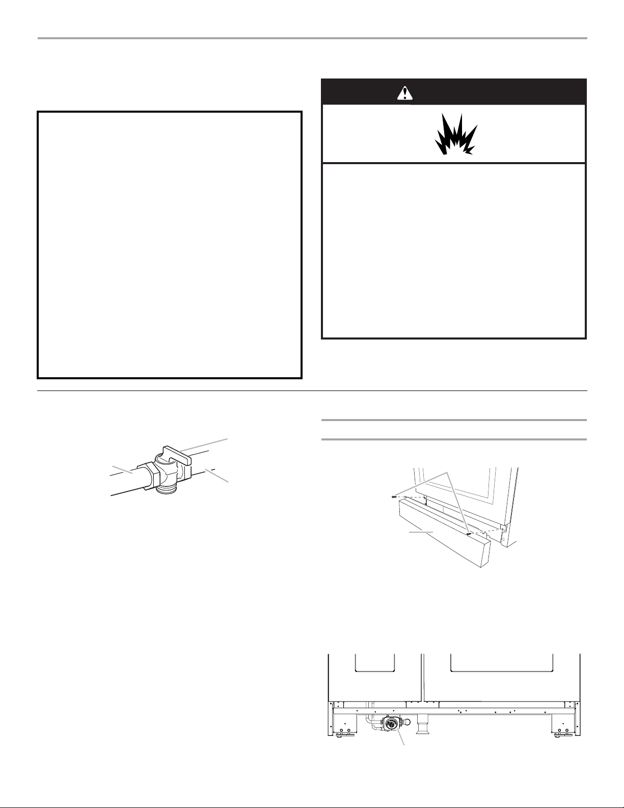
1. Turn the manual shutoff valve to the closed position.
B
A
A. To range
B. Shutoff valve (closed position)
C. Gas supply line
2. Unplug range or disconnect power.
To Convert Gas Pressure Regulator
1. Remove screws from kick plate.
B
A
A. Kick plate
B. Remove these screws.
2. Push up on kick plate to release plate from shoulder screws.
3. Gently lay kick plate aside to avoid scratching the stainless
steel.
4. Locate the gas pressure regulator at the left rear of the range.
A
A. Gas pressure regulator
3
Page 4

5. Remove the gas pressure regulator cap by using a large flat-
blade screwdriver, turning the regulator cap
counterclockwise.
NOTE: Do not remove the spring beneath the cap.
6. Turn over the gas pressure regulator cap and reinstall on the
regulator:
For Natural gas to LP, the hollow end faces outward and the
letters “LP” are visible.
For LP to Natural gas, the hollow end faces inward and the
letters “NAT” are visible.
Gas Supply Pressure Testing
Gas supply pressure for testing regulator must be at least
1" water column pressure above the manifold pressure
shown on the model/serial rating plate.
Line pressure testing above ½ psi gauge (14" WCP)
The range and its individual shutoff valve must be
disconnected from the gas supply piping system during any
pressure testing of that system at test pressures in excess of
½ psi (3.5 kPa).
Line pressure testing at ½ psi gauge (14" WCP) or lower
The range must be isolated from the gas supply piping
system by closing its individual manual shutoff valve during
any pressure testing of the gas supply piping system at test
pressures equal to or less than ½ psi (3.5 kPa).
To Convert Oven Bake Burner (30" [76.2 cm] and 36"
[91.4 cm] models and the Right Oven Cavity on 48"
[121.9 cm] models)
1. Remove oven racks and the extendable roller rack from
inside the oven cavity. See the “Extendable Roller Rack”
section in the Use and Care Guide.
WARNING
Excessive Weight Hazard
Use two or more people to move and install oven
doors.
Failure to do so can result in back or other injury.
7. Tighten the gas pressure regulator cap by using a large flat-
blade screwdriver, turning the regulator cap clockwise.
8. Test the gas pressure regulator and gas supply line.
The regulator must be checked at a minimum 1" (2.5 cm)
water column above the set pressure. The inlet pressure to
the regulator should be as follows for operation and checking
the regulator setting:
LP Gas:
Minimum pressure 11" (27.9 cm) WCP
Maximum pressure 14" (35.6 cm) WCP
2. Remove the oven door. See the “Oven Door” section in the
Use and Care Guide.
3. Slide the bake burner cover to the right or left.
A
A. Bake burner cover
4. Lift up and remove oven bake burner cover and set aside.
4
Page 5

5. Unscrew oven baffle nuts and remove oven baffle. Set aside.
7. Lift up clip on the oven bake burner electrode bracket with a
finger or flat-blade screwdriver.
B
A
A
A. Oven baffle
B. Oven baffle nuts
B
6. Remove the oven bake burner screws and oven bake burner
and gently set aside.
DC
A
A. Oven bake burner screws
B. Oven bake burner
C. Oven bake burner electrode bracket
D. Oven bake burner electrode
B
A. Oven bake burner electrode bracket
B. Electrode bracket clip
8. Pull electrode out of bracket.
A
B
A. Grasp electrode here.
B. Bracket
5
Page 6

9. Apply masking tape to the end of a 7 mm nut driver to help
A
hold the gas orifice spud in the nut driver while changing it.
Insert nut driver into the gas opening and press down onto
the gas orifice spud and remove by turning the gas orifice
spud counterclockwise and lifting out. Set gas orifice spud
aside.
13. Replace oven bake burner electrode inside bracket.
B
A
A. Gas orifice spud
10. Gas orifice studs are stamped with a letter and a number.
For Natural gas:
Install the Number 177 oven bake burner orifice spud.
For LP gas:
Install the Number 115 oven bake burner orifice spud.
11. Place the original gas orifice in plastic parts bag for future use
and keep with package containing literature.
12. Push down on the clip on the electrode bracket.
A
A. Oven bake burner electrode
B. Oven bake burner electrode bracket
14. Reinstall the oven bake burner and oven bake burner screws.
See Step 6 for illustration.
15. Replace oven baffle and oven baffle nuts.
Replace Oven Bake Burner Cover
1. Align notches on the oven bake burner cover with shoulder
screws in the bottom of the oven.
B
A
A. Oven bake burner electrode bracket
B. Electrode bracket clip
A
B
A. Cover notches (4)
B. Shoulder screws (4)
B
6
Page 7

2. Lower cover and slide to left or right to slide shoulder screws
A
into the narrow ends of the notches and lock in place.
A
A. Bake burner cover
2. Pull the broil burner toward you until it slides out of the hole in
the oven back, and pull the electrode out of the bracket. The
broil burner will hang down in the back of the oven while you
change the orifice.
B
To Convert Oven Broil Burner (30" [76.2 cm] and 36"
[91.4 cm] models and the Right Oven Cavity on 48"
[121.9 cm] models)
1. Remove broil burner screw and set aside.
A
B
C
A. Broil burner screw
B. Broil burner
C. Broil burner orifice hole
A. Grasp electrode here.
B. Bracket
3. Apply masking tape to the end of a 7 mm nut driver to help
hold the gas orifice spud in the nut driver while changing it.
Insert nut driver into the gas opening and press down onto
the gas orifice spud and remove by turning the gas orifice
spud counterclockwise and lifting out. Set gas orifice spud
aside.
A
A. Oven back
B. Broil burner orifice
C. Broil burner orifice hole
C
B
7
Page 8

4. Gas orifice studs are stamped with a letter and a number.
A
B
For Natural gas:
Install the Number 132 oven bake burner orifice spud.
For LP gas:
Install the Number 89 oven bake burner orifice spud.
5. Place the original gas orifice in plastic parts bag for future use
and keep with package containing literature.
6. Replace the broil burner in the hole in the oven back, with the
broil burner electrode inside the broil burner electrode hole,
as illustrated.
A
A. Broil burner orifice hole
B. Broil burner electrode
C. Broil burner electrode hole
BC
To Convert Oven Bake Burner (Left Oven Cavity on
48" [121.9 cm] models)
1. Remove oven racks.
2. Remove the oven door. See the “Oven Door” section in the
Use and Care Guide.
3. Slide the bake burner cover to the right or left.
A
A. Bake burner cover
4. Lift up and remove oven bake burner cover and set aside.
5. Remove the oven bake burner screws and oven bake burner
and gently set aside.
7. Reinstall the oven broil burner screw. See Step 1 for
illustration.
A
D
C
A. Oven bake burner
B. Oven bake burner screws
C. Oven bake burner electrode bracket
D. Oven bake burner electrode
8
Page 9

6. Lift up clip on the oven bake burner electrode bracket with a
finger or flat-blade screwdriver
B
A
A. Oven bake burner electrode bracket
B. Electrode bracket clip
8. Apply masking tape to the end of a 7 mm nut driver to help
hold the gas orifice spud in the nut driver while changing it.
Insert nut driver into the gas opening and press down onto
the gas orifice spud and remove by turning the gas orifice
spud counterclockwise and lifting out. Set gas orifice spud
aside.
A
7. Pull electrode out of bracket.
A
B
A. Grasp electrode here.
B. Bracket
A. Gas orifice spud
9. Gas orifice studs are stamped with a letter and a number.
For Natural gas:
Install the Number 140 oven bake burner orifice spud.
For LP gas:
Install the Number 97 oven bake burner orifice spud.
10. Place the original gas orifice in plastic parts bag for future use
and keep with package containing literature.
11. Push down on the clip on the electrode bracket.
B
A
A. Oven bake burner electrode bracket
B. Electrode bracket clip
9
Page 10
12. Replace oven bake burner electrode inside bracket.
B
A
A
C
A
C
D
B
A
C
B
B
A
2. Drop cover and slide to left or right to slide shoulder screws
into narrow ends of keyholes and lock in place.
A
A. Bake burner cover
A. Oven bake burner electrode
B. Oven bake burner electrode bracket
13. Reinstall the oven bake burner and oven bake burner screws.
See Step 5 for illustration.
Replace Oven Bake Burner Cover
1. Align rear shoulder screw mounting holes (keyholes) on the
oven bake burner cover with shoulder screws in the bottom
of the oven.
A. Shoulder screw mounting holes (keyholes)
B. Shoulder screws
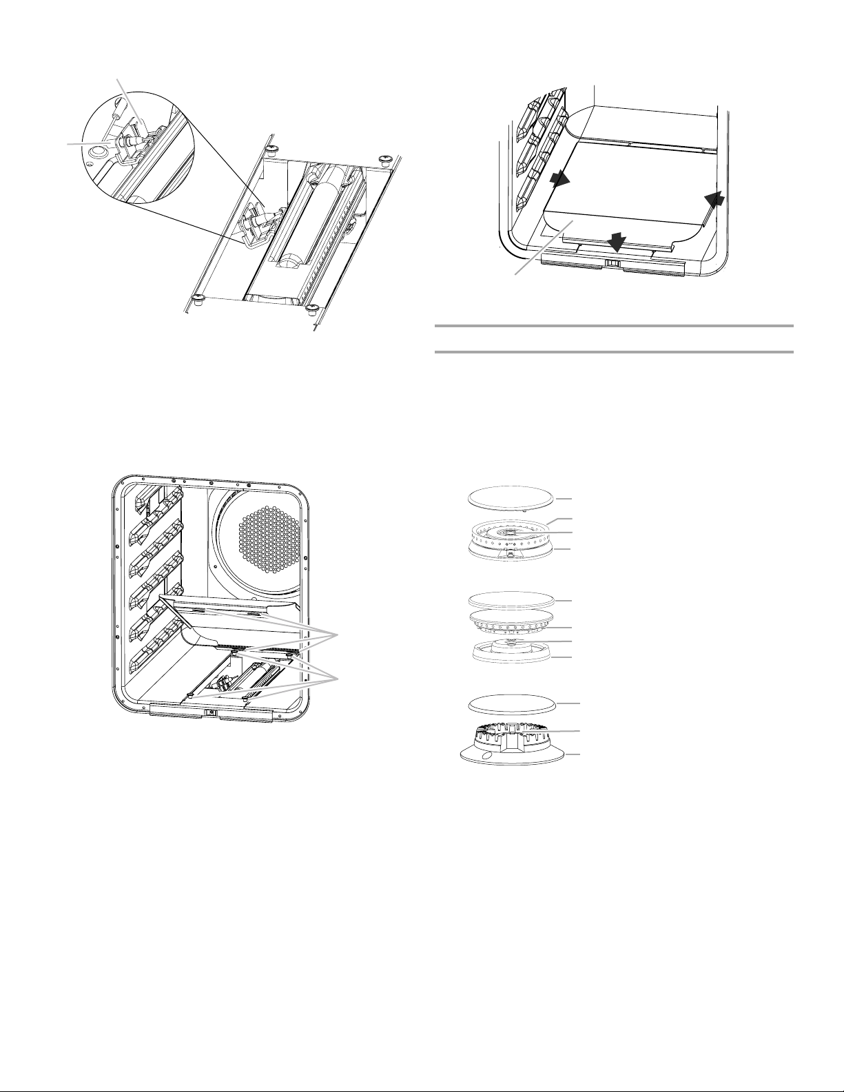
To Convert Surface Burners
1. If burner grates are installed, remove them.
2. Remove burner cap.
3. Remove the burner head.
NOTE: A ⁷⁄₈" socket must be used to remove the burner head
of the large dual burners.
†
®
4. Using a T15 Torx
screwdriver, remove the burner base.
Large Dual Burner
A. Burner cap
B
D
B. Burner head
C. Gas opening
D. Burner base
Medium Burner
A. Burner cap
B. Burner head
C. Gas opening
D. Burner base
Small Burner
A. Burner cap
B. Gas opening
C. Burner base
10
®†TORX is a registered trademark of Saturn Fasteners, Inc.
Page 11

5. Apply masking tape to the end of a 7 mm nut driver to help
hold the gas orifice spud in the nut driver while changing it.
Insert nut driver into the gas opening and press down onto
the gas orifice spud and remove by turning the gas orifice
spud counterclockwise and lifting out. Set gas orifice spud
aside.
6. Replace with correct Natural gas/LP gas orifice spud. See the
following “Gas Orifice Spud/Hood Chart.”
Use the following chart to find the exact orifice spud
placement.
Gas Orifice Spud/Hood Chart
Gas
Type
LP
NG
LP
NG
Burner
Rating
3,000
BTU
5,000
BTU
Do not
replace
12,500
BTU
15,000
BTU
Color Size Burner Style
Blue
Brass
Brass
Brass
0.55
mm
1.01
mm
#94
#159
Small burners
Medium burners
Gas orifice spud
A
A. Size stamp or color
7. Place the original gas orifice in plastic parts bag for future use
and keep with package containing literature.
8. Replace the burner base using both screws.
9. Replace burner head and cap.
10. Repeat steps 2 through 9 for the remaining burners.
11. Proceed to Instruction Sheet W10257664A.
LP
NG
LP
NG
15,500
BTU
20,000
BTU
Brass
Green
Brass
Brass
Brass
Brass
#094
0.45
mm
#170
0.69
mm
#107
#177
Large burner - main
Large burner simmer (do not
replace simmer)
Large burner - main
Large burner simmer (do not
replace simmer)
Griddle burner
11
Page 12

W10352797A
© 2010. Whirlpool Corporation.
All rights reserved.
Printed in U.S.A.
10/10
 Loading...