

Whirlpool W10224585A, W10224594A User Manual
ELECTRIC DRYER INSTALLATION INSTRUCTIONS
U.S.A. ONLY
TABLE OF CONTENTS
DRYER SAFETY..............................................................................1
INSTALLATION REQUIREMENTS ................................................2
Tools and Parts ............................................................................ 2
Optional Equipment .....................................................................2
Location Requirements................................................................3
ELECTRIC DRYER POWER HOOKUP
Electrical Requirements - U.S.A. Only......................................... 6
Electrical Connection - U.S.A. Only............................................. 7
VENTING .......................................................................................11
Venting Requirements................................................................11
.........................................6
DRYER SAFETY
Your safety and the safety of others are very important.
We have provided many important safety messages in this manual and on your appliance. Always read and obey all safety
messages.
Plan Vent System .......................................................................12
Install Vent System.....................................................................13
INSTALL LEVELING LEGS...........................................................13
CONNECT VENT...........................................................................13
CONNECT INLET HOSE (STEAM MODELS)..............................14
LEVEL DRYER ..............................................................................14
COMPLETE INSTALLATION .......................................................14
TROUBLESHOOTING ..................................................................15
This is the safety alert symbol.
This symbol alerts you to potential hazards that can kill or hurt you and others.
All safety messages will follow the safety alert symbol and either the word “DANGER” or “WARNING.”
These words mean:
You can be killed or seriously injured if you don't immediately
DANGER
WARNING
All safety messages will tell you what the potential hazard is, tell you how to reduce the chance of injury, and tell you what can
happen if the instructions are not followed.
Para una version de estas intrucciones en español, visite www.Whirlpool.com
follow instructions.
can be killed or seriously injured if you don't
You
instructions.
follow
W10224585A
INSTALLATION REQUIREMENTS
To o l s a n d Parts
Gather the required tools and parts before starting installation. Read and follow the instructions provided with any tools listed here.
Steam Models
■ Flat-blade screwdriver
■ #2 Phillips screwdriver
■ Adjustable wrench that
opens to 1" (25 mm) or
hex-head socket wrench
(for adjusting dryer feet)
■ Level
■ Wire stripper (direct wire
installations)
■ Vent cl amps
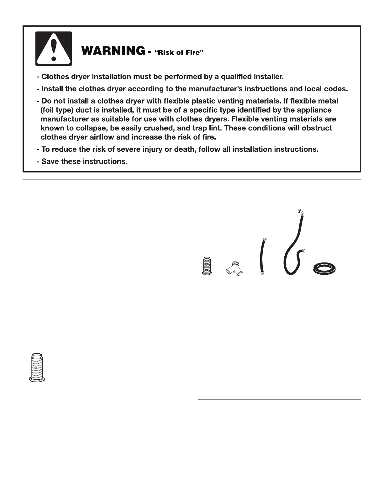
Parts supplied
Non-Steam Models
4 Leveling legs
■ Caulking gun and compound
(for installing new exhaust
vent)
■ Tin snips (new vent
installations)
■ ¼" nut driver
(recommended)
■ Tap e me as u re
■ Pliers
A
A. Leveling legs (4)
B. “Y” connector
C. Short inlet hose
B
C
D
D. Inlet hose with right-angle
connector
E. Rubber washer
E
Remove parts package from dryer drum. Check that all parts are included.
NOTE: Do n
ot use leveling legs supplied with dryer if installing
on a pedestal.
Parts needed
Check local codes. Check existing electrical supply and venting. See “Electrical Requirements” and “Venting Requirements” before purchasing parts.
Mobile home installations require m
etal exhaust system hardware
available for purchase from the dealer from whom you purchased
your dryer. For further information, please refer to the “Assistance
or Service” section in your Use and Care Gui
de.
Optional Equipment
Refer to your Use and Care guide for information about the accessories available for your dryer.
2
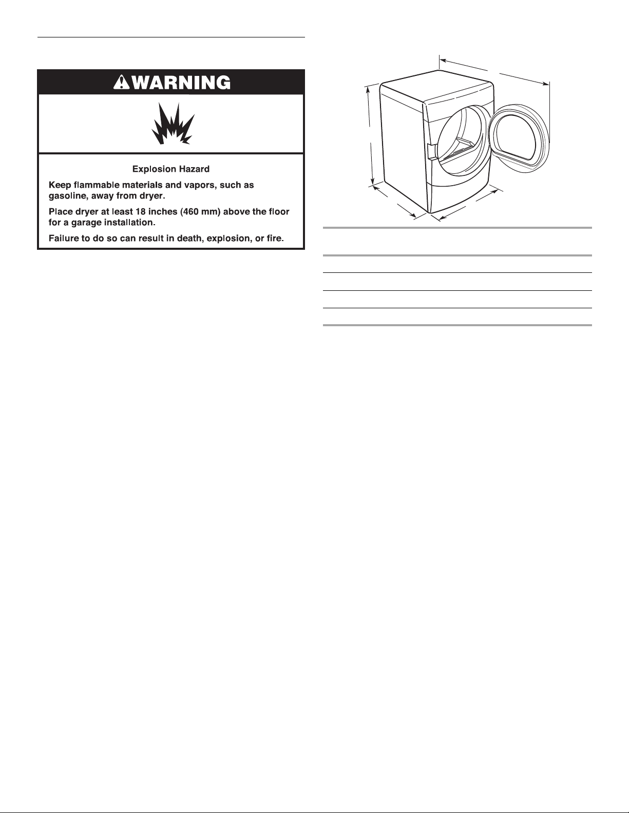
Location Requirements
Dryer Dimensions
D
A
You will need
■ A location that allows for proper exhaust installation. See
“Venting Requirements.”
■ A separate 30-amp circuit.
■ If you are using a power supply cord, a grounded electrical
outlet located within 2 ft (610 mm) of either side of the dryer.
See “Electrical Requirements.”
■ A sturdy floor to support the total dryer weight of 200 lbs
(90.7 kg). The combined weight of a companion appliance
should
also be considered.
■ A level floor with a maximum slope of 1" (25 mm) under entire
dryer. If slope is greater than 1" (25 mm), install Extended Dryer
Feet Kit, Part Number 279810. Clothes may not tumble properly
and automatic sensor cycles may not operate correctly if dryer is
not level.
■ For a garage installation, you will need to place the dryer at least
18" (460 mm) above the floor. If using a pedestal, you will need
18" (460 mm) to the bottom of the dryer.
■ Steam models only: Cold water faucets located within 4 ft
(1.2 m) of the dryer, and water pressure of 20-100 psi
(137.9-689.6 kPa). You may use the cold water supply from
your washer using the “Y” connector provided.
Do not operate your dryer at temperatur
lower temperatures, the dryer might not shut off at the end of an
automatic sensor cycle. This can result in longer drying times.
The dryer must not be installed or st
be exposed to water and/or weather.
Check code requirements. Some codes limit, or
installation of the dryer in garages, closets, mobile homes, or
sleeping quarters. Contact your local building inspector.
es below 45ºF (7ºC). At
ored in an area where it will
do not permit,
B
Steam
(Electric or Gas)
C
Non-Steam
(Electric or Gas)
A 38" (9652 mm) 38" (9652 mm)
B 32
9
/16" (686 mm) 31 1/2" (800 mm)
C 27" (686 mm) 27" (686 mm)
9
D 52
NOTE: Most installations r
/16" (1335 mm) 51 1/2" (1308 mm)
equire a minimum 5" (127 mm) clearance
behind the dryer for the exhaust vent with elbow.
See “Venting Requirements.”
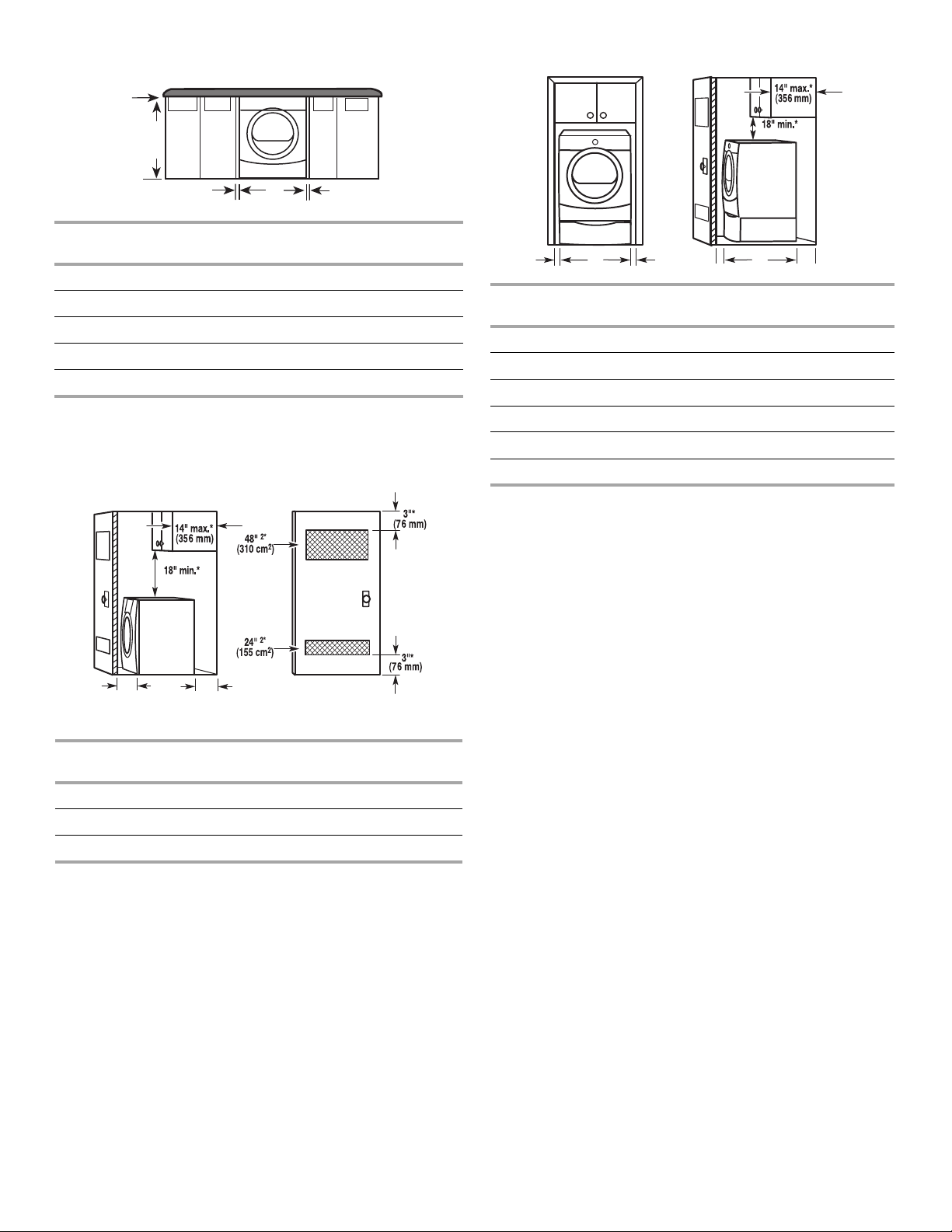
Installation spacing for recessed area or closet installation
The following spacing dimensions are recommended for this dryer.
This dryer has been tested for spacing of 0" (0 mm) clearance on the
sides an
following reasons:
■ Additional spacing should be considered for ease of installation
■ Additional clearances might be required for wall, door, and floor
■ Additional spacing should be considered on all sides of the dryer
■ For closet installation, with a door, minimum ventilation openings
■ Companion appliance spacing should also be considered.
d rear. Recommended spacing should be considered for the
and servicing.
moldings.
to reduce noise transfer.
in the top and bottom of the door are required. Louvered doors
with equivalent ventilation openings are acceptable.
Installation clearances
The location must be large enough to allow the dryer door to open fully.
3
Custom undercounter installation - Dryer only
A
A
Recessed or cl
oset installation - Dryer on pedesta
l
B
C* DE*
Steam
(Electric or Gas)
Non-Steam
(Electric or Gas)
A 0" (0 mm) 0" (0 mm)
B 38" (9652 mm) 38" (9652 mm)
C* 1" (25 mm) 1" (25 mm)
D 27" (686 mm) 27" (686 mm)
E* 1" (25 mm) 1" (25 mm)
*Required spacing
Some models are not recommended for undercounter
NOTE:
installation.
Closet installation - Dryer only
(460 mm)
(460 mm)
B C D* E
Steam
(Electric or G
as)
(Electric or Gas)
F**
Non-Steam
A 1" (25 mm) 1" (25 mm)
B 27" (686 mm) 27" (686 mm)
C 1" (25 mm) 1" (25 mm)
D* 1" (25 mm) 1" (25 mm)
E 32 9/16" (686 mm) 31 1/2" (800 mm)
F** 5" (127 mm) 5" (127 mm)
*Required spacing
**For side or bottom venting, 0" (0 mm) spacing is allowed
NOTE: Some
models are not recommended for recessed or closet
installation.
A*
B C**
Side view
Steam
(Electric or Gas)
Closet door with vents
Non-Steam
(Electric or Gas)
A* 1" (25 mm) 1" (25 mm)
9
B 32
/16" (686 mm) 31 1/2" (800 mm)
C** 5" (127 mm) 5" (127 mm)
*Required spacing
**For side or bottom venting, 0" (0 mm) spacing is allowed.
4
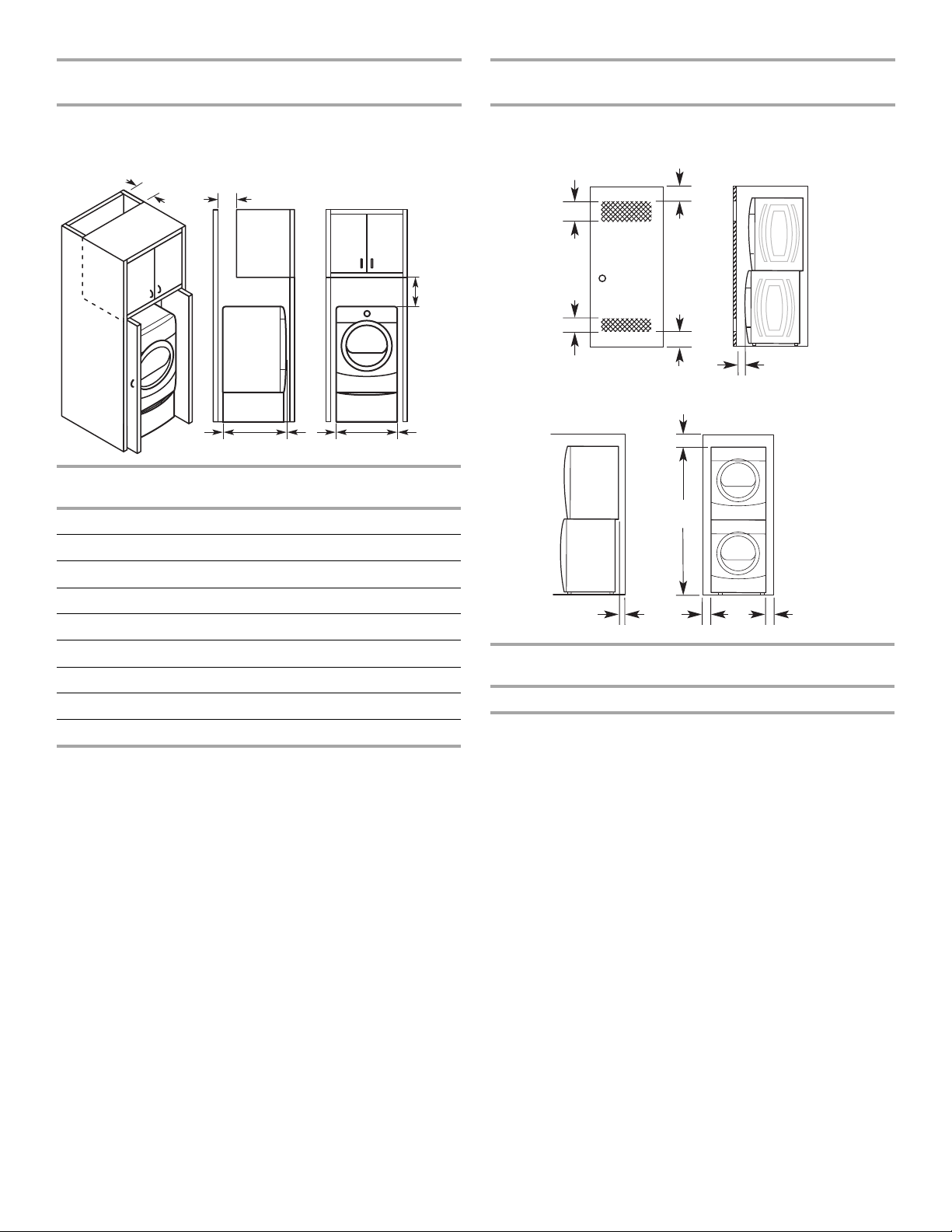
Recommended installation spacing for cabinet installation
Recommended installation spacing for recessed or closet installation, with stacked washer and dryer
NOTE: Some models are not recommended for cabinet installation.
■ For cabinet installation, with a door, minimum ventilation
openings in the top of the cabinet are required.
A*
B*
C*
D**
Steam
(Electric or Gas)
E
G
F*
H
Non-Steam
(Electric or Gas)
I
A* 7" (178 mm) 7" (178 mm)
B* 7" (178 mm) 7" (178 mm)
C* 9" (229 mm) 9" (229 mm)
D** 5" (127 mm) 5" (127 mm)
9
E 32
/16" (686 mm) 31 1/2" (800 mm)
The dimensions shown are for the recommended spacing.
48 in.2 *
2
(310 cm
)
3"* (76 mm)
3"* (76 mm)
2
24 in.
(155 cm2)
*
A*
6"* (152 mm)
76"
(1930 mm)
1"
(25 mm)
27"
(686 mm)
1"* (25 mm)
1"
(25 mm)
F* 1" (25 mm) 1" (25 mm)
G 1" (25 mm) 1" (25 mm)
H 27" (686 mm) 27" (686 mm)
I 1" (25 mm) 1" (25 mm)
*Required spacing
**For side or bottom venting, 0" (0 mm) spacing is allowed.
Steam
(Electric or Gas)
Non-Steam
(Electric or Gas)
A 5 ½" (140 mm) 5" (127 mm)
*Required spacing
NOTE: Some
models are not recommended for stacked recessed or
closet installation.
Mobile home - Additional installation requirements
This dryer is suitable for mobile home installations. The installation
must conform to the Manufactured Home Construction and Safety
Standard, Title 24 CFR, Part 3280 (formerly the Federal Standard for
Mobile Home Construction and Safety, Title 24, HUD Part 280) or
Standard CAN/CSA-Z240 MH.
Mobile home installations require:
All Dryers:
■ Metal exhaust system hardware, which is available for purchase
from your dealer.
■ Special provisions must be made in mobile homes to introduce
outside air into the dryer. The opening (such as a nearby
window) should be at least twice as large as the dryer exhaust
opening.
5
 Loading...