


W10115228C

DRYER INSTALLATION INSTRUCTIONS
29" and 27" Wide Models
Gas (U.S.A. and Canada) & Electric (Canada Only)
INSTRUCTIONS D’INSTALLATION DE LA SÉCHEUSE
Modèles de 29" et de 27" de largeur
À gaz (É.-U. et Canada) et Électrique (Canada uniquement)
Para obtener acceso al manual de uso y cuidado en español, o para obtener información adicional acerca de su producto, visite:
Tenga listo su número de modelo completo. Puede encontrar el número de modelo y de serie dentro de la cavidad superior de la puerta.
Table of Contents
DRYER SAFETY ................................................................ 2
INSTALLATION REQUIREMENTS ....................................4
Tools and Parts .................................................................... 4
Location Requirements ...................................................... 5
ELECTRIC DRYER POWER HOOKUP – CANADA ONLY ......... 7
Electrical Requirements ..................................................... 7
Install Leveling Legs ........................................................... 7
GAS DRYER POWER HOOKUP ................................................. 8
Gas Supply Requirements .................................................. 8
Electrical Requirements ..................................................... 9
VENTING .................................................................................... 10
Venting Requirements ....................................................... 10
Plan Vent System ...............................................................11
Venting Kits ........................................................................ 11
Install Vent System ............................................................ 12
Make Gas Connection ...................................................... 13
Connect Vent .....................................................................13
LEVEL DRYER ........................................................................... 14
COMPLETE INSTALLATION CHECKLIST ............................... 14
REVERSE DOOR SWING (OPTIONAL) .................................... 14
TROUBLESHOOTING ............................................................... 22
www.whirlpool.com
SÉCURITÉ DE LA SÉCHEUSE ....................................... 23
EXIGENCES D’INSTALLATION ......................................25
Outillage et pièces ............................................................ 25
Exigences d’emplacement ............................................... 26
RACCORDEMENT À L’ALIMENTATION ÉLECTRIQUE
DE LA SÉCHEUSE ÉLECTRIQUE – CANADA SEULEMENT ... 28
Spécications électriques ................................................ 28
Installation des pieds de nivellement .............................. 29
RACCORDEMENT D’UNE SÉCHEUSE À GAZ .......................29
Spécications de l’alimentation en gaz .......................... 29
Spécications électriques ................................................ 31
L’ÉVACUATION.......................................................................... 32
Exigences concernant l’évacuation ................................ 32
Planication du système d’évacuation ........................... 33
Trousses d’évacuation ...................................................... 33
Installation du circuit d’évacuation ................................. 35
Raccordement au gaz ....................................................... 35
Raccordement du conduit d’évacuation ......................... 36
RÉGLAGE DE L’APLOMB DE LA SÉCHEUSE......................... 36
ACHEVER L’INSTALLATION – LISTE DE VÉRIFICATION ....... 37
INVERSION DU SENS DE L’OUVERTURE DE LA PORTE
(FACULTATIF)
DÉPANNAGE ............................................................................. 47
Table des matières
............................................................................. 37
INSTALLATION NOTES
Date of purchase: _________________________________
Date of installation: _______________________________
Installer: ________________________________________
Model number: ___________________________________
Serial number: ___________________________________
W10115228C
W10115229C-SP
NOTES CONCERNANT L’INSTALLATION
Date d’achat : _____________________________________
Date d’installation : ________________________________
Installateur : ______________________________________
Numéro de modèle : ________________________________
Numéro de série : __________________________________
1
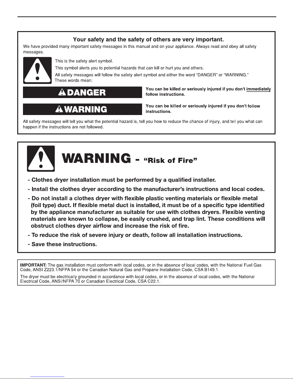
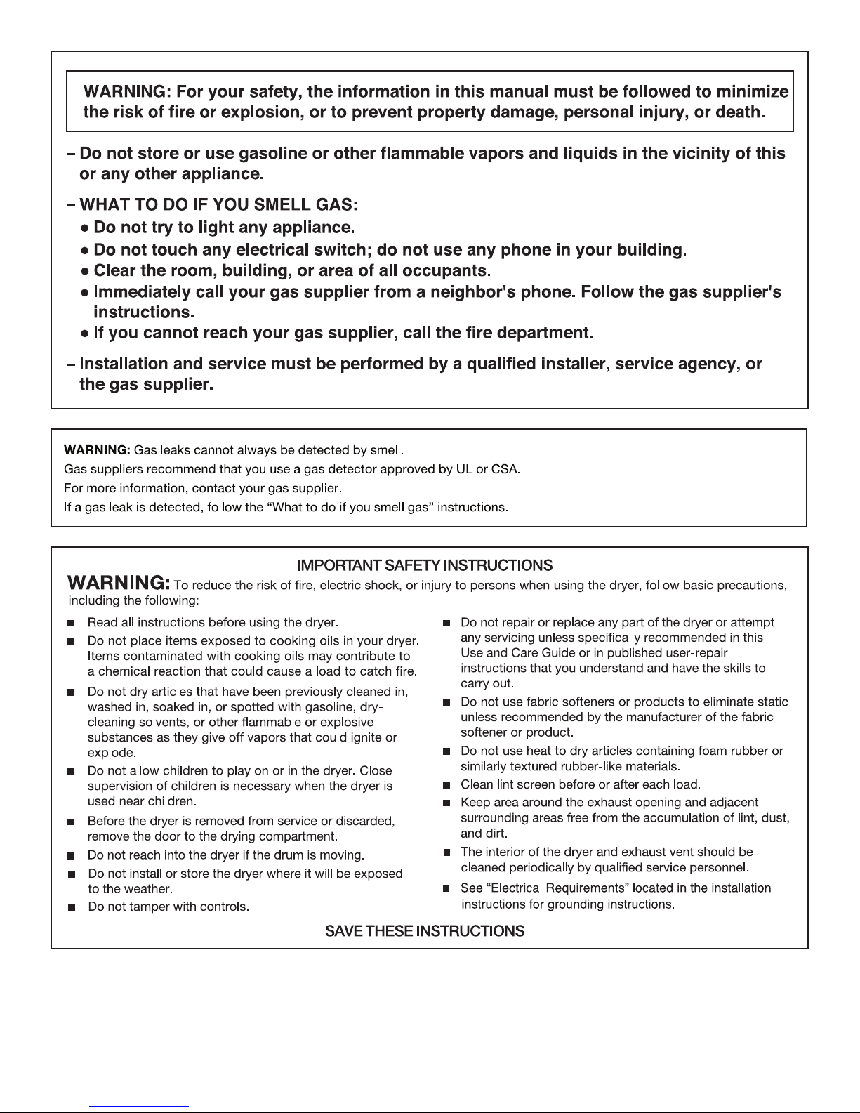
DRYER SAFETY
2
3
INSTALLATION REQUIREMENTS
Tools and Parts
Gather the required tools and parts before starting installation.
Tools needed for all installations:
Flat-blade screwdriver #2 Phillips screwdriver
1/4" nut driver or socket
wrench (recommended)
Tape measure
Tin snips (new vent
installations)
Vent clamps
Adjustable wrench that
opens to 1" (25 mm) or
hex-head socket wrench
Utility knife
Caulking gun and compound
(for installing new exhaust vent)
Putty knife
Tools needed for gas installations:
8" or 10" pipe wrench
8" or 10" adjustable wrench
(for gas connections)
Level
Pliers
4
Pipe-joint compound
resistant to LP gas
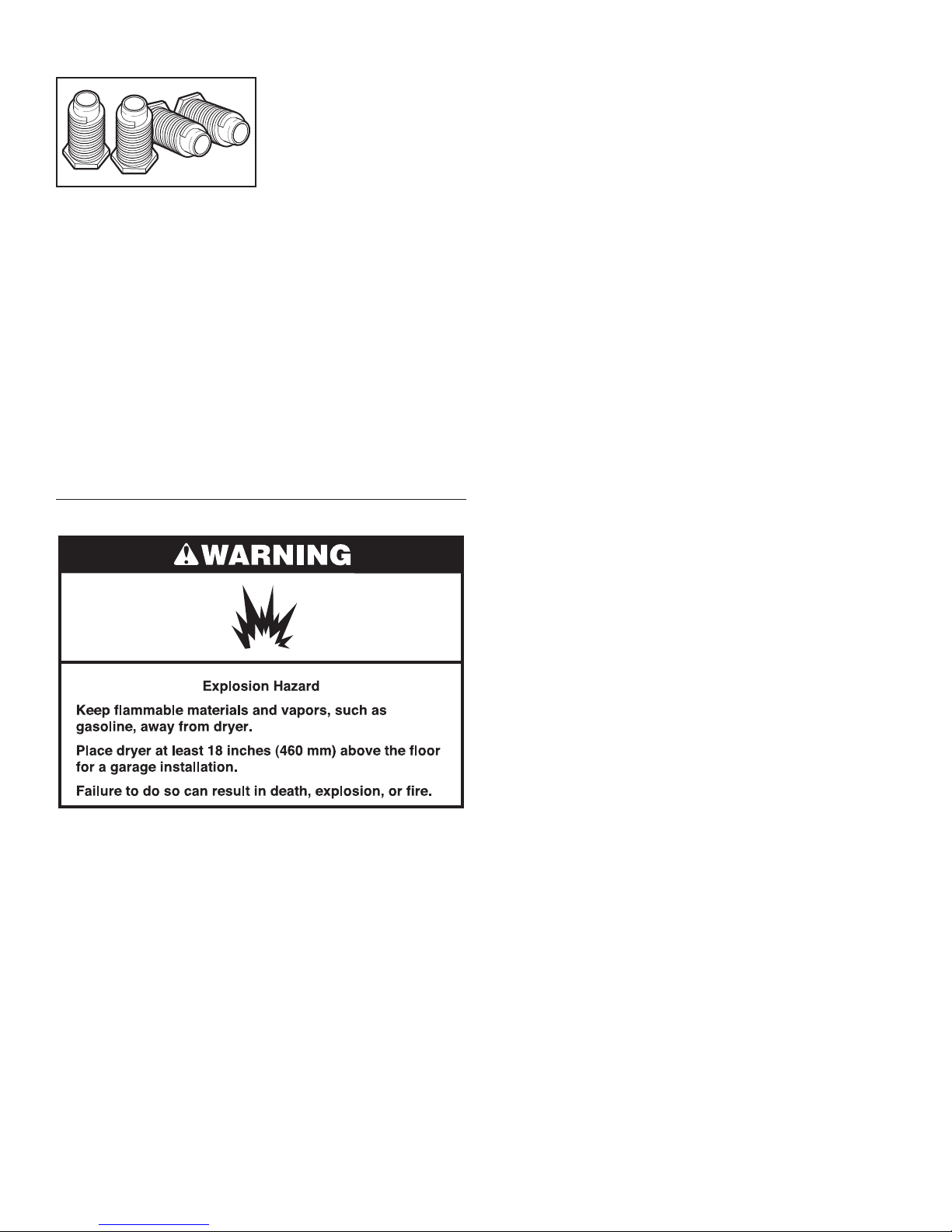
Parts supplied:
Leveling legs (4)
Parts package is located in dryer drum. Check that all parts
are included.
Parts needed:
Check local codes. Check existing electrical supply and venting.
See “Electrical Requirements” and “Venting Requirements”
before purchasing parts.
Mobile home installations require metal exhaust system
hardware, available for purchase from the dealer from whom
you purchased your dryer. For further information, please
reference the “Assistance or Service” section of the Use and
Care Guide.
Optional Equipment: (Not supplied with dryer)
Refer to your Use and Care Guide for information about
accessories available for your dryer.
■ If you are using power supply cord, a grounded electrical
outlet located within 2 ft. (610 mm) of either side of dryer.
See “Electrical Requirements.”
■ A sturdy oor to support dryer and a total weight (dryer
and load) of 200 lbs. (90.7 kg). The combined weight of
a companion appliance should also be considered.
■ Level oor with maximum slope of 1" (25 mm) under entire
dryer. If slope is greater than 1" (25 mm), install Extended
Dryer Feet Kit, Part Number 279810. If not level, clothes
may not tumble properly and automatic sensor cycles
may not operate correctly.
Do not operate your dryer at temperatures below 45°F (7°C).
At lower temperatures, the dryer might not shut off at the end
of an automatic cycle. Drying times can be extended.
The dryer must not be installed or stored in an area where it will
be exposed to water and/or weather.
Check code requirements. Some codes limit, or do not permit,
installation of the dryer in garages, closets, mobile homes, or
sleeping quarters. Contact your local building inspector.
NOTE: No other fuel-burning appliance can be installed in the
same closet as a dryer.
Location Requirements
You will need:
■ A location allowing for proper exhaust installation.
See “Venting Requirements.”
■ A separate 30-amp circuit for electric dryers.
■ A separate 15- or 20-amp circuit for gas dryers.
5
Installation clearances:
The location must be large enough to allow the dryer door to open fully.
Most installations require a minimum 5½" (140 mm) clearance behind the dryer for the exhaust vent with elbow. See “Venting
Requirements.”
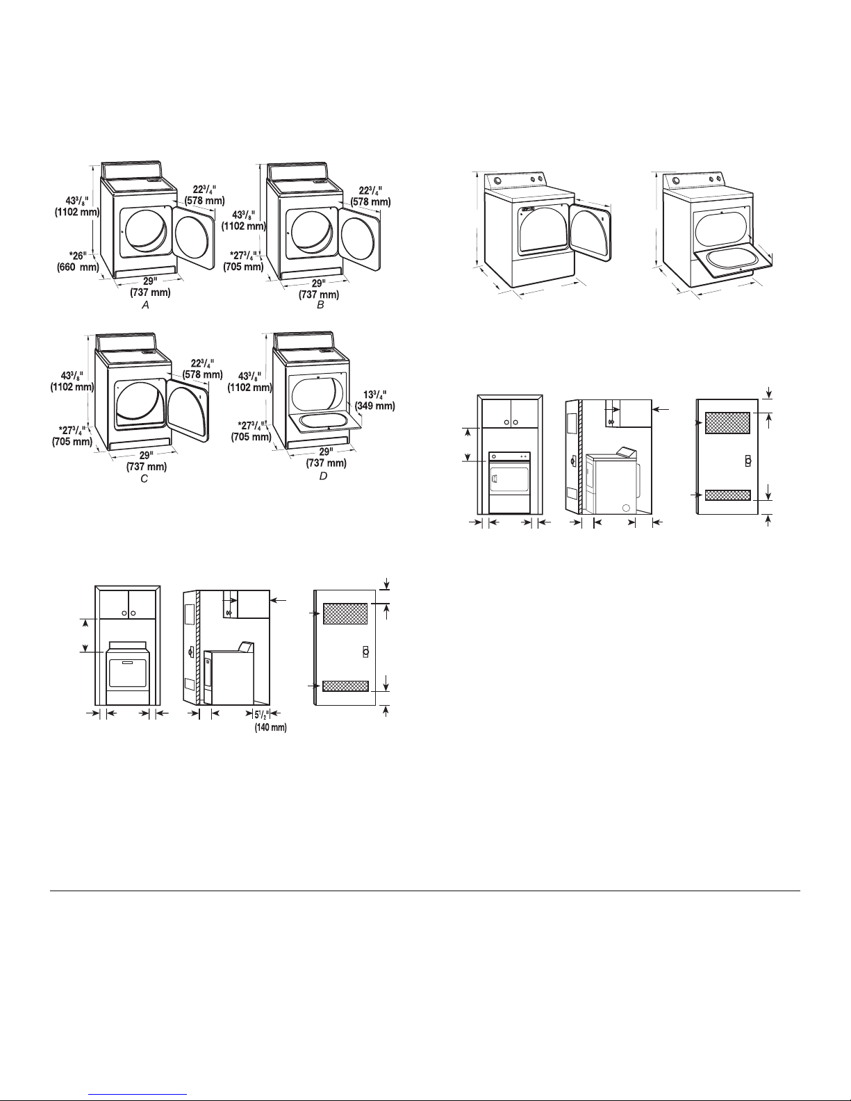
29" Wide Models
Dryer Dimensions
A. Large opening side-swing door
B. Large opening side-swing door
C. Wide opening side-swing door
D. Wide opening hamper door
Installation Spacing
18"*
(457 mm)
1"
(25 mm)
*Required spacing
29"
(737 mm)
A
1"
(25 mm)
A. Recessed area
B. Side view – closet or conned area
C. Closet door with vents
1"*
(25 mm)
27¾"
(705 mm)
B
14" max.*
(356 mm)
2
48 in.
(310 cm )
24 in.
(155 cm )
27" Wide Models
Dryer Dimensions
23¾"
27"
(603 mm)
43"
(1092 mm)
*291/2"
(749 mm)
(687 mm)
B
27"
13¾"
(349 mm)
43"
(1092 mm)
*291/2"
(749 mm)
(687 mm)
A
A. Large opening side-swing door
B. Wide opening hamper door
Installation Spacing
3"*
(76 mm)
18"*
14" max.*
(356 mm)
48 in.
(310 cm )
2
*
2
(457 mm)
2
*
1"
(25 mm)
27"
(686 mm)
A
1"
(25 mm)
1"*
(25 mm)
29
¼"
(743 mm)
B
5½"*
(140 mm)
24 in.
(155 cm )
2
C
3"*
(76 mm)
A. Recessed area
3"*
(76 mm)
*
2
*Required spacing
B. Side view – closet or conned area
C. Closet door with vents
Installation spacing for recessed area or closet
The dimensions shown are for the minimum spacing allowed.
2
*
2
3"*
(76 mm)
C
■ Additional spacing should be considered for ease of
installation and servicing.
■ Additional clearances might be required for wall, door, and
oor moldings.
■ Additional spacing of 1" (25 mm) on all sides of the dryer is
recommended to reduce noise transfer.
■ For closet installation, with a door, minimum ventilation
openings in the top and bottom of the door are required.
Louvered doors with equivalent ventilation openings are
acceptable.
■ Companion appliance spacing should also be considered.
Mobile home – Additional installation requirements
This dryer is suitable for mobile home installations. The
installation must conform to the Manufactured Home
Construction and Safety Standard, Title 24 CFR, Part 3280
(formerly the Federal Standard for Mobile Home Construction
and Safety, Title 24, HUD Part 280) or the Canadian
Manufactured Home Standard CAN/CSA-Z240 MH.
6
■ Metal exhaust system hardware, available for purchase.
For further information, please reference the “Assistance or
Service” section of the Use and Care Guide.
■ Special provisions must be made in mobile homes to
introduce outside air into the dryer. The opening (such as a
nearby window) should be at least twice as large as the dryer
exhaust opening.
ELECTRIC DRYER POWER
HOOKUP – CANADA ONLY
Electrical Requirements
It is your responsibility:
■ To contact a qualied electrical installer.
■ To be sure that the electrical connection is adequate
and in conformance with the Canadian Electrical Code,
C22.1 – latest edition and all local codes. A copy of the
above codes standard may be obtained from: Canadian
Standards Association, 178 Rexdale Blvd., Toronto, ON
M9W 1R3 CANADA.
■ To supply the required 4-wire, single-phase, 120/240 volt,
60 Hz., AC-only electrical supply on a separate 30-amp
circuit, fused on both sides of the line. A time-delay fuse or
circuit breaker is recommended. Connect to an individual
branch circuit.
■ This dryer is equipped with a CSA International Certied
Power Cord intended to be plugged into a standard 14-30R
wall receptacle. The cord is 5 ft. (1.52 m) in length. Be sure
wall receptacle is within reach of dryer’s nal location.
GROUNDING INSTRUCTIONS
■
For a grounded, cord-connected dryer:
This dryer must be grounded. In the event of malfunction or
breakdown, grounding will reduce the risk of electric shock
by providing a path of least resistance for electric current.
This dryer is equipped with a cord having an equipmentgrounding conductor and a grounding plug. The plug must
be plugged into an appropriate outlet that is properly
installed and grounded in accordance with all local codes
and ordinances.
WARNING: Improper connection of the equipment-
grounding conductor can result in a risk of electric shock.
Check with a qualied electrician or service representative
or personnel if you are in doubt as to whether the dryer is
properly grounded. Do not modify the plug provided with
the dryer: if it will not t the outlet, have a proper outlet
installed by a qualied electrician.
SAVE THESE INSTRUCTIONS
Install Leveling Legs
1.
Prepare dryer for leveling legs
4-wire receptacle (14-30R)
Do not use an extension cord.
■
If using a replacement power supply cord, it is recommended that
you use Power Supply Cord Replacement Part Number 8579325.
For further information, please reference the “Assistance or
Service” section of the Use and Care Guide.
To avoid damaging oor, use a large at piece of cardboard
from dryer carton; place under entire back edge of dryer.
Firmly grasp dryer body (not console panel) and gently lay
dryer down on cardboard.
7
 Loading...